Kawasaki Wheel Loader ZX300 7 Operational & Service Manual & Parts Manual
Original price was: $93.95.$37.95Current price is: $37.95.
Kawasaki Wheel Loader ZX300 7 Operational & Service Manual & Parts Manual – PDF DOWNLOAD
Description
Kawasaki Wheel Loader ZX300 7 Operational & Service Manual & Parts Manual
File Details:
Kawasaki Wheel Loader ZX300 7 Operational & Service Manual & Parts Manual
Language : English
Pages : 500+
Size : 248 MB
Downloadable : Yes
Format : PDF
KAWASAKI WHEEL LOADER ZX300 7 OPERATIONAL & SERVICE MANUAL & PARTS MANUAL:
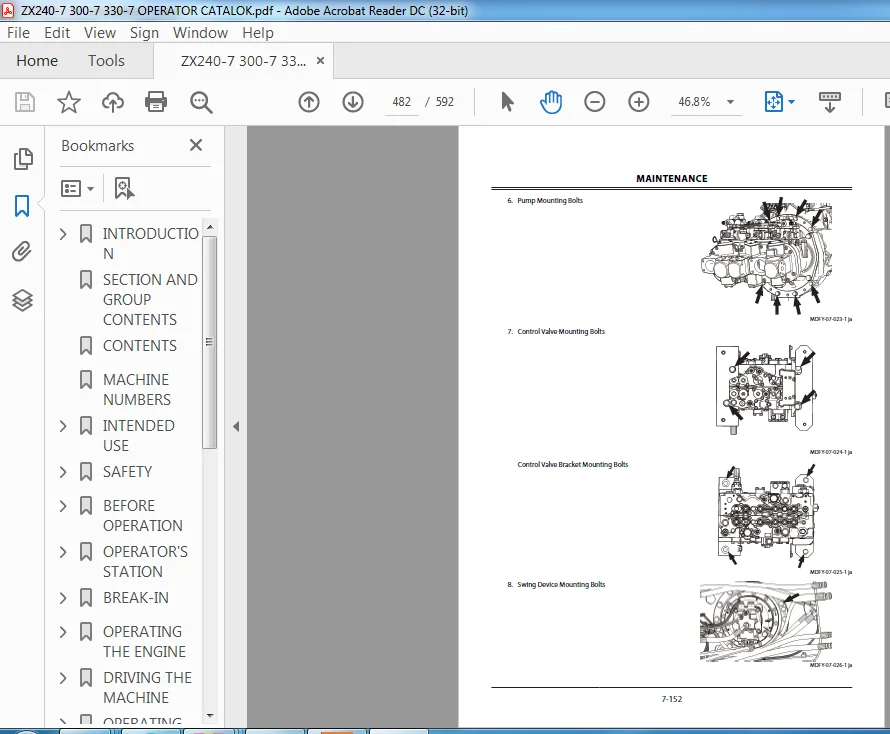
Image Preview:
Table of Contents:
Kawasaki Wheel Loader ZX300 7 Operational & Service Manual & Parts Manual
Cab………………………………………………..W3-1-1-1
Removal of Cab Interior Parts……………………………….W3-1-1-1
Removal of Cab Exterior Parts………………………………W3-1-2-1
Removal of Cab Body…………………………………………….W3-1-3-1
Removal of Controller Assembly and Parts Around the Monitor…………………………………………………………W3-1-4-1
Installation of Controller Assembly and Parts Around the Monitor………………………………………….W3-1-5-1
Installation of Cab Body………………………………………..W3-1-6-1
Installation of Cab Exterior Parts………………………….W3-1-7-1
Installation of Cab Interior Parts…………………………..W3-1-8-1
Dimensions of Cab Glass……………………………………….W3-1-9-1
Procedure to Remove Cab Glass……………………….W3-1-10-1
Procedure to Install Cab Glass……………………………W3-1-11-1
Procedures to Install Upper Door Glass……………W3-1-12-1
Procedures to Install Upper Front Glass…………..W3-1-13-1
Counterweight……………………………….W3-2-1-1
Removal of Counterweight…………………………………..W3-2-1-1
Installation of Counterweight………………………………W3-2-2-1
Main Frame……………………………………W3-3-1-1
Removal of Main Frame…………………………………………W3-3-1-1
Installation of Main Frame…………………………………….W3-3-2-1
Engine……………………………………………W3-4-1-1
Preparation before Removal of Engine……………….W3-4-1-1
Removal of Covers and Related Parts Around the Engine………………………………………………………………….W3-4-2-1
Removal of Wire Harnesses and Hoses Around the Engine………………………………………………………………….W3-4-3-1
Removal of Engine Body……………………………………….W3-4-4-1
Installation of Engine Body…………………………………..W3-4-5-1
Installation of Wire Harnesses and Hoses Around the Engine…………………………………………………………..W3-4-6-1
Installation of Related Parts of the Engine…………W3-4-7-1
Work after Installation of Engine and Installation of Covers……………………………………………………………..W3-4-8-1
Radiator Assembly…………………………W3-5-1-1
Removal of Radiator………………………………………………W3-5-1-1
Installation of Radiator…………………………………………..W3-5-2-1
Removal of Intercooler………………………………………….W3-5-3-1
Installation of Intercooler………………………………………W3-5-4-1
Removal of Oil Cooler…………………………………………….W3-5-5-1
Installation of Oil Cooler………………………………………..W3-5-6-1
Hydraulic Oil Tank………………………….W3-6-1-1
Removal of Hydraulic Oil Tank……………………………..W3-6-1-1
Installation of Hydraulic Oil Tank…………………………W3-6-2-1
Fuel Tank……………………………………….W3-7-1-1
Removal of Fuel Tank……………………………………………..W3-7-1-1
Installation of Fuel Tank…………………………………………W3-7-2-1
Pump Device………………………………….W3-8-1-1
Removal of Pump Device………………………………………W3-8-1-1
Installation of Pump Device………………………………….W3-8-2-1
Removal of Coupling……………………………………………..W3-8-3-1
Installation of Coupling…………………………………………W3-8-4-1
Disassembly of Pump Device……………………………….W3-8-5-1
Assembly of Pump Device…………………………………….W3-8-6-1
Disassembly of Regulator……………………………………..W3-8-7-1
Assembly of Regulator…………………………………………..W3-8-8-1
Disassembly of Solenoid Valve…………………………….W3-8-9-1
Assembly of Solenoid Valve……………………………….W3-8-10-1
Structure of Pilot Pump………………………………………W3-8-11-1
Control Valve………………………………….W3-9-1-1
Removal of Control Valve………………………………………W3-9-1-1
Installation of Control Valve………………………………….W3-9-2-1
Disassembly of Housing………………………………………..W3-9-3-1
Assembly of Housing……………………………………………..W3-9-4-1
Disassembly of Spool (A-Side Control Valve)……..W3-9-5-1
Assembly of Spool (A-Side Control Valve)………….W3-9-6-1
Disassembly of Boom Anti-Drift Valve (Check Valve) (j) (A-Side Control Valve)……………………….W3-9-7-1
Disassembly of Boom Anti-Drift Valve (Selector Valve) (k) (A-Side Control Valve)………………………W3-9-8-1
Assembly of Boom Anti-Drift Valve (j, k) (A-Side Control Valve)…………………………………………………….W3-9-9-1
Disassembly of Overload Relief Valve (h, i, ac, ad) (A-Side Control Valve)…………………………………….W3-9-10-1
Assembly of Overload Relief Valve (h, i, ac, ad) (A-Side Control Valve)………………………………………….W3-9-11-1
Disassembly of Travel (Right) Spool (n) (A-Side Control Valve)………………………………………………….W3-9-12-1
Assembly of Travel Spool (n) (A-Side Control Valve)………………………………………………………………..W3-9-13-1
Disassembly of Bucket Spool (p) (A-Side Control Valve)………………………………………………………………..W3-9-14-1
WDD650-EN-00(16/03/2020)
Assemble of Bucket Spool (p) (A-Side Control Valve)………………………………………………………………..W3-9-15-1
Disassembly of Arm 2 Spool (q) (A-Side Control Valve)………………………………………………………………..W3-9-16-1
Assembly of Arm 2 Spool (q) (A-Side Control Valve)………………………………………………………………..W3-9-17-1
Disassembly of Boom 1 Spool (r) (A-Side Control Valve)………………………………………………………………..W3-9-18-1
Assembly of Boom 1 Spool (r) (A-Side Control Valve)………………………………………………………………..W3-9-19-1
Disassembly of Boom 3 Spool (s) (A-Side Control Valve)………………………………………………………………..W3-9-20-1
Assembly of Boom 3 Spool (s) (A-Side Control Valve)………………………………………………………………..W3-9-21-1
Disassembly of Swing Spool (t) (A-Side Control Valve)………………………………………………………………..W3-9-22-1
Assembly of Swing Spool (t) (A-Side Control Valve)………………………………………………………………..W3-9-23-1
Disassembly of Arm Roll-In Meter-Out Open Control Spool (aa) (A-Side Control Valve)……W3-9-24-1
Assembly of Arm Roll-In Meter-Out Open Control Spool (aa) (A-Side Control Valve)………………….W3-9-25-1
Disassembly of Main Relief Valve (m) (A-Side Control Valve)………………………………………………….W3-9-26-1
Assembly of Main Relief Valve (m) (A-Side Control Valve)………………………………………………………………..W3-9-27-1
Disassembly of Bucket Regeneration Cut Valve (g) (A-Side Control Valve)…………………………………….W3-9-28-1
Assembly of Bucket Regeneration Cut Valve (g) (A-Side Control Valve)…………………………………….W3-9-29-1
Disassembly of Check Valve (d, f) (A-Side Control Valve)………………………………………………………………..W3-9-30-1
Assembly of Check Valve (d, f) (A-Side Control Valve)………………………………………………………………..W3-9-31-1
Disassembly of Load Check Valve (e) (A-Side Control Valve)………………………………………………….W3-9-32-1
Assembly of Load Check Valve (e) (A-Side Control Valve)………………………………………………………………..W3-9-33-1
Disassembly of Flow Combiner Valve (ae) (A-Side Control Valve)………………………………………………….W3-9-34-1
Assembly of Flow Combiner Valve (ae) (A-Side Control Valve)………………………………………………….W3-9-35-1
Disassembly of Pump 1 Bypass Shut-Out Valve (ab) (A-Side Control Valve)…………………………….W3-9-36-1
Assembly of Pump 1 Bypass Shut-Out Valve (ab) (A-Side Control Valve)…………………………………….W3-9-37-1
Disassembly of Check Valves (u, w), Load Check Valves (x, y) (A-Side Control Valve)……………….W3-9-38-1
Assembly of Check Valves (u, w), Load Check Valves (x, y) (A-Side Control Valve)……………….W3-9-39-1
Disassembly of Boom Lower Meter-In Cut Valve (v) (A-Side Control Valve)……………………………….W3-9-40-1
Assembly of Boom Lower Meter-In Cut Valve (v) (A-Side Control Valve)…………………………………….W3-9-41-1
Disassembly of Load Check Valve (z) (A-Side Control Valve)………………………………………………….W3-9-42-1
Assembly of Load Check Valve (z) (A-Side Control Valve)………………………………………………………………..W3-9-43-1
Disassembly and Assembly of Plugs (A-Side Control Valve)………………………………………………….W3-9-44-1
Disassembly of Spool (B-Side Control Valve)…..W3-9-45-1
Assembly of Spool (B-Side Control Valve)………..W3-9-46-1
Disassembly of Arm Regenerative Valve (j) (B-Side Control Valve)………………………………………………….W3-9-47-1
Assembly of Arm Regenerative Valve (j) (B-Side Control Valve)………………………………………………….W3-9-48-1
Disassembly of Arm Rod Anti-Drift Valve (Check Valve) (e) (B-Side Control Valve)……………………W3-9-49-1
Disassembly of Arm Rod Anti-Drift Valve (Selector Valve) (d) (B-Side Control Valve)……………………W3-9-50-1
Assembly of Arm Rod Anti-Drift Valve (d, e) (B-Side Control Valve)………………………………………….W3-9-51-1
Disassembly of Overload Relief Valve (f, aa) (B-Side Control Valve)………………………………………….W3-9-52-1
Assembly of Overload Relief Valve (f, aa) (B-Side Control Valve)………………………………………………….W3-9-53-1
Disassembly of Main Relief Valve (ai) (B-Side Control Valve)………………………………………………….W3-9-54-1
Assembly of Main Relief Valve (ai) (B-Side Control Valve)………………………………………………………………..W3-9-55-1
Disassembly of Load Check Valve (Arm Regenerative Circuit) (ac) (B-Side Control Valve)……………………………………………………………………………W3-9-56-1
Assembly of Load Check Valve (Arm Regenerative Circuit) (ac) (B-Side Control Valve)………………..W3-9-57-1
Disassembly of Load Check Valve (Travel (Left) Tandem Circuit) (ag) (B-Side Control Valve)..W3-9-58-1
Assembly of Load Check Valve (Travel (Left) Tandem Circuit) (ag) (B-Side Control Valve)..W3-9-59-1
Disassembly of Check Valve (Main Relief Circuit) (ah) (B-Side Control Valve)……………………………..W3-9-60-1
Assembly of Check Valve (Main Relief Circuit) (ah) (B-Side Control Valve)…………………………………….W3-9-61-1
Disassembly of Travel (Left) Spool (g) (B-Side Control Valve)………………………………………………….W3-9-62-1
Assembly of Travel (Left) Spool (g) (B-Side Control Valve)………………………………………………………………..W3-9-63-1
Disassembly of Auxiliary 1 Spool (h) (B-Side Control Valve)………………………………………………….W3-9-64-1
Assembly of Auxiliary 1 Spool (h) (B-Side Control Valve)………………………………………………………………..W3-9-65-1
Disassembly of Arm 1 Spool (i) (B-Side Control Valve)………………………………………………………………..W3-9-66-1
Assembly of Arm 1 Spool (i) (B-Side Control Valve)……………………………………………………………………………W3-9-67-1
Disassembly of Boom 2 Spool (k) (B-Side Control Valve)………………………………………………………………..W3-9-68-1
Assembly of Boom 2 Spool (k) (B-Side Control Valve)………………………………………………………………..W3-9-69-1
Disassembly of Pump 3 Bypass Shut-Out Valve (ae) (B-Side Control Valve)……………………………..W3-9-70-1
WDD650-EN-00(16/03/2020)
Assembly of Pump 3 Bypass Shut-Out Valve (ae) (B-Side Control Valve)…………………………………….W3-9-71-1
Disassembly of Auxiliary 2 Spool (m) (B-Side Control Valve)………………………………………………….W3-9-72-1
Assembly of Auxiliary 2 Spool (m) (B-Side Control Valve)………………………………………………………………..W3-9-73-1
Disassembly of Digging Regenerative Valve (ab) (B-Side Control Valve)…………………………………….W3-9-74-1
Assembly of Digging Regenerative Valve (ab) (B-Side Control Valve)………………………………………….W3-9-75-1
Disassembly of Auxiliary Flow Combiner Valve (z) (B-Side Control Valve)…………………………………….W3-9-76-1
Assembly of Auxiliary Flow Combiner Valve (z) (B-Side Control Valve)………………………………………….W3-9-77-1
Disassembly of Arm Bottom Anti-Drift Valve (Check Valve) (y) (B-Side Control Valve)………W3-9-78-1
Disassembly of Arm Bottom Anti-Drift Valve (Selector Valve) (x) (B-Side Control Valve)…..W3-9-79-1
Assembly of Arm Bottom Anti-Drift Valve (x, y) (B-Side Control Valve)………………………………………….W3-9-80-1
Disassembly of Check Valve (Auxiliary Flow Combiner Circuit) (af) (B-Side Control Valve)W3-9-81-1
Assembly of Check Valve (Auxiliary Flow Combiner Circuit) (af) (B-Side Control Valve)W3-9-82-1
Disassembly of Arm 1 Flow Rate Control Valve (Poppet Valve) (s) (B-Side Control Valve)…….W3-9-83-1
Disassembly of Arm 1 Flow Rate Control Valve (Selector Valve) (t) (B-Side Control Valve)……W3-9-84-1
Assembly of Arm 1 Flow Rate Control Valve (s, t) (B-Side Control Valve)…………………………………….W3-9-85-1
Disassembly of Load Check Valve (Boom 2 Parallel Circuit) (u) (B-Side Control Valve)…………………W3-9-86-1
Assembly of Load Check Valve (Boom 2 Parallel Circuit) (u) (B-Side Control Valve)…………………W3-9-87-1
Disassembly of Load Check Valve (Auxiliary 2 Tandem Circuit) (r) (B-Side Control Valve)…..W3-9-88-1
Assembly of Load Check Valve (Auxiliary 2 Tandem Circuit) (r) (B-Side Control Valve)…..W3-9-89-1
Disassembly of Load Check Valve (Travel (Left) Parallel Circuit) (n) (B-Side Control Valve)……W3-9-90-1
Assembly of Load Check Valve (Travel Parallel Circuit) (n) (B-Side Control Valve)…………………W3-9-91-1
Disassembly of Load Check Valve (Auxiliary 2 Parallel Circuit) (ad) (B-Side Control Valve)….W3-9-92-1
Assembly of Load Check Valve (Auxiliary 2 Parallel Circuit) (ad) (B-Side Control Valve)……………….W3-9-93-1
Disassembly of Load Check Valve (Digging Regenerative Circuit) (w) (B-Side Control Valve)……………………………………………………………………………W3-9-94-1
Assembly of Load Check Valve (Digging Regenerative Circuit) (w) (B-Side Control Valve)……………………………………………………………………………W3-9-95-1
Disassembly of Auxiliary Flow Rate Control Valve (Poppet Valve) (p) (B-Side Control Valve)…….W3-9-96-1
Disassembly of Auxiliary Flow Rate Control Valve (Selector Valve) (q) (B-Side Control Valve)…..W3-9-97-1
Assembly of Auxiliary Flow Rate Control Valves (p, q) (B-Side Control Valve)………………………………..W3-9-98-1
Disassembly of Auxiliary 2 Hydraulic Pressure Source Control Spool (ak) (B-Side Control Valve)………………………………………………………………..W3-9-99-1
Assembly of Auxiliary 2 Hydraulic Pressure Source Control Spool (ak) (B-Side Control Valve)….W3-9-100-1
Disassembly and Assembly of Plugs (B-Side Control Valve)………………………………………………..W3-9-101-1
Swing Device………………………………..W3-10-1-1
Removal of Swing Device…………………………………..W3-10-1-1
Installation of Swing Device………………………………W3-10-2-1
Disassembly of Swing Reduction Gear…………….W3-10-3-1
Assembly of Swing Reduction Gear………………….W3-10-4-1
Disassembly of Swing Motor……………………………..W3-10-5-1
Assembly of Swing Motor…………………………………..W3-10-6-1
Structure of Swing Parking Brake Selection Valve……………………………………………………………………………..W3-10-7-1
Pilot Valve……………………………………W3-11-1-1
Removal of Pilot Valve (Left)………………………………W3-11-1-1
Installation of Pilot Valve (Left)………………………….W3-11-2-1
Removal of Pilot Valve (Right)……………………………W3-11-3-1
Installation of Pilot Valve (Right)……………………….W3-11-4-1
Disassembly of Pilot Valves (Left and Right)……W3-11-5-1
Assembly of Pilot Valves (Left and Right)…………W3-11-6-1
Removal of Travel Pilot Valve……………………………..W3-11-7-1
Installation of Travel Pilot Valve…………………………W3-11-8-1
Disassembly of Travel Pilot Valve………………………W3-11-9-1
Assembly of Travel Pilot Valve………………………….W3-11-10-1
Solenoid Valve……………………………..W3-12-1-1
Removal of Pilot Shut-Off Shut-OffShut-OffShut-Off Solenoid Valve………..W3-12-1-1
Installation of Pilot Shut-Off Shut-OffShut-OffShut-Off Solenoid Valve……W3-12-2-1
Disassembly of Pilot Shut-Off Shut-OffShut-OffShut-Off Solenoid Valve…W3-12-3-1
Assembly of Pilot Shut-Off Shut-OffShut-OffShut-Off Solenoid Valve………W3-12-4-1
Removal of 5-Spool Solenoid Valve Unit………….W3-12-5-1
Installation of 5-Spool Solenoid Valve Unit……..W3-12-6-1
Structure of 5-Spool Solenoid Valve Unit…………W3-12-7-1
Removal of 2-Spool Solenoid Valve Unit………….W3-12-8-1
Installation of 2-Spool Solenoid Valve Unit……..W3-12-9-1
Structure of 2-Spool Solenoid Valve Unit……….W3-12-10-1
Removal of 3-Spool Solenoid Valve Unit………..W3-12-11-1
Installation of 3-Spool Solenoid Valve Unit……W3-12-12-1
Structure of 3-Spool Solenoid Valve Unit……….W3-12-13-1
Signal Control Valve……………………..W3-13-1-1
Removal of Signal Control Valve……………………….W3-13-1-1
Installation of Signal Control Valve…………………..W3-13-2-1
Structure of Signal Control Valve………………………W3-13-3-1
Aftertreatment Device………………….W3-14-1-1
Removal of Aftertreatment Device……………………W3-14-1-1
Installation of Aftertreatment Device……………….W3-14-2-1
DEF Tank………………………………………W3-15-1-1
WDD650-EN-00(16/03/2020)
Removal of DEF Tank…………………………………………..W3-15-1-1
Installation of DEF Tank………………………………………W3-15-2-1
Removal of DEF Tank Suction Filter…………………..W3-15-3-1
Installation of DEF Tank Suction Filter………………W3-15-4-1
Removal of DEF Tank Water Supply Inlet Filter.W3-15-5-1
Installation of DEF Tank Water Supply Inlet Filter………………………………………………………………………………W3-15-6-1
Assembly of DEF Tank Water Supply Inlet FilterW3-15-7-1
Coolant Control Valve…………………..W3-16-1-1
Removal of Coolant Control Valve…………………….W3-16-1-1
Installation of Coolant Control Valve………………..W3-16-2-1
DEF Supply Module………………………W3-17-1-1
Removal of DEF Supply Module………………………..W3-17-1-1
Installation of DEF Supply Module……………………W3-17-2-1
WDD650-EN-00(16/03/2020)
Description:
Kawasaki Wheel Loader ZX300 7 Operational & Service Manual & Parts Manual
- Read this manual carefully to learn how to operate and service your machine correctly. Failure to do so could result in personal injury or machine damage. This standard specification specification specification machine can be operated under the following conditions without being modified. modified.Atmospheric Temperature: –20 °C to 40 °C (–4 °F to 104 °F) Altitude: 0 m to 2000 m (0 ft to 6600 ft) In case the machine is used under conditions other than described above, consult your authorized dealer
- . This manual should be considered a permanent part of your machine and should remain with the machine when you sell it. This machine is of metric design. Measurements in this manual are metric. Use only metric hardware and tools as specified. specified. Right-hand and left-hand sides are determined by facing in the direction of forward travel. Write product identification identification identification numbers in the Machine Numbers section. Accurately record all the numbers to help in tracing the machine should it be stolen.
- Your dealer also needs these numbers when you order parts. If this manual is kept on the machine, also file the identification identification numbers in a secure place off the machine. Be sure to use fuel that complies with JIS K-2204, EN-590 or ASTM D-975 which contains 15 ppm or lower sulfur. Also use fuel that complies with solid contamination level of class 18/16/13 of ISO4406-1999 (solid contamination includes dust).
- If the fuel specified above is not used, exhaust gas that exceeds the regulation values may be discharged, causing serious problem on the engine. Consult your authorized dealer. Warranty is provided as a part of Hitachi’s support program for customers who operate and maintain their equipment as described in this manual. The warranty is explained on the warranty certificatecertificate certificate certificate which you should have received from your dealer.
- This warranty provides you the assurance that Hitachi will back its products where defects appear within the warranty period. In some circumstances, Hitachi also provides field improvements, often without charge to the customer, even if the product is out of warranty. Should the equipment be abused, or modified modified to change its performance beyond the original factory specifications, specifications, specifications, specifications, the warranty will become void and field improvements may be denied.
- Setting fuel delivery above specifications or otherwise overpowering machines will result in such action. Only qualified, qualified, experienced operators officially licensed (according to local law) should be allowed to operate the machine. Moreover, only officially licensed personnel should be allowed to inspect and service the machine.
- PRIOR TO OPERATING THIS MACHINE, INCLUDING COMMUNICATION SYSTEM, IN A COUNTRY OTHER THAN A COUNTRY OF ITS INTENDED USE, IT MAY BE NECESSARY TO MAKE MODIFICATIONS TO IT SO THAT IT COMPLIES WITH THE LOCAL REGULATORY STANDARDS (INCLUDING SAFETY STANDARDS) AND LEGAL REQUIREMENTS OF THAT PARTICULAR COUNTRY. PLEASE DO NOT EXPORT OR OPERATE THIS MACHINE OUTSIDE OF THE COUNTRY OF ITS INTENDED USE UNTIL SUCH COMPLIANCE HAS BEEN CONFIRMED. PLEASE CONTACT HITACHI CONSTRUCTION MACHINERY CO., LTD. OR ANY OF OUR AUTHORIZED DISTRIBUTOR OR DEALER IF YOU HAVE ANY QUESTIONS CONCERNING COMPLIANCE.
- In this manual, urea water is indicated as DEF/ AdBlue®. “DEF” stands for the Diesel Exhaust Fluid. AdBlue® is a registered trademark of the Verband der Automobilindustrie e.V. (VDA). The Bluetooth® word mark and logos are registered trademarks owned by Bluetooth SIG,Inc. and any use of such marks by Hitachi Construction Machinery Co., Ltd. is under license. Other trademarks and trade names are those of their respective owners.
- All information, illustrations and specifications in this manual are based on the latest product information available at the time of publication. The right is reserved to make changes at any time without notice.
Please Note:
- This is the SAME exact manual used by your dealers to fix your vehicle.
- The same can be yours in the next 2-3 mins as you will be directed to the download page immediately after paying for the manual.
- Any queries / doubts regarding your purchase, please feel free to contact [email protected]