Kawasaki Wheel Loader ZX890 7 Operational & Service Manual & Parts Manual
Original price was: $93.95.$37.95Current price is: $37.95.
Kawasaki Wheel Loader ZX890 7 Operational & Service Manual & Parts Manual – PDF DOWNLOAD
Description
Kawasaki Wheel Loader ZX890 7 Operational & Service Manual & Parts Manual
File Details:
Kawasaki Wheel Loader ZX890 7 Operational & Service Manual & Parts Manual
Language : English
Pages : 500+
Size : 132 MB
Downloadable : Yes
Format : PDF
KAWASAKI WHEEL LOADER ZX890 7 OPERATIONAL & SERVICE MANUAL & PARTS MANUAL:
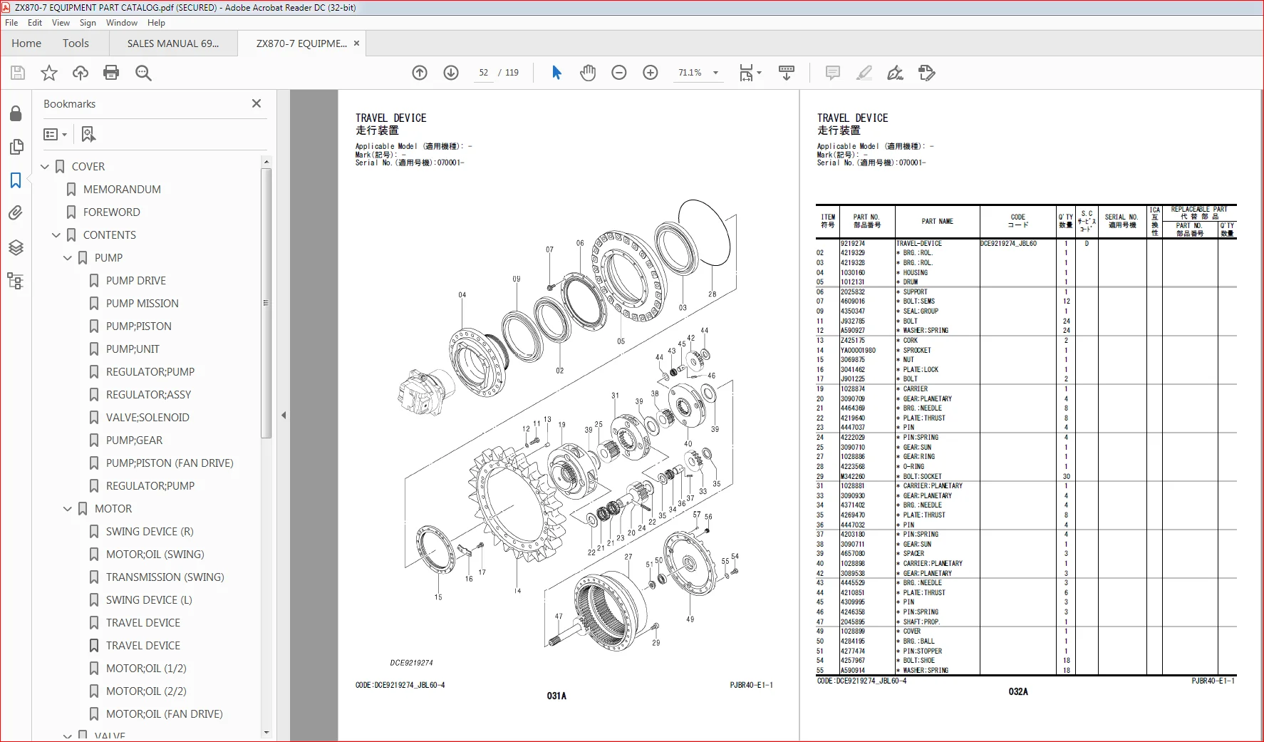
Image Preview:
Table of Contents:
Kawasaki Wheel Loader ZX890 7 Operational & Service Manual & Parts Manual
Diagnosing Procedure ………………………..T5-1-1
Introduction………………………………………………………………… T5-1-1
Diagnosis Procedure………………………………………………….. T5-1-2
Electrical System Inspection …………………………………….. T5-1-5
Precautions for Inspection and Maintenance………… T5-1-5
Instructions for Disconnecting Connectors …………… T5-1-7
Instructions for Removing Relays ……………………………. T5-1-9
Fuse Inspection………………………………………………………….T5-1-11
Fuse Connection Destination………………………………….T5-1-11
Fusible Link Inspection …………………………………………….T5-1-13
Battery Voltage Check………………………………………………T5-1-16
Alternator Check ……………………………………………………….T5-1-16
Continuity Check ………………………………………………………T5-1-18
Voltage and Current Measurement of 24-Volt
Circuit……………………………………………………………………..T5-1-19
Voltage and Current Measurement of 5-Volt
Circuit……………………………………………………………………..T5-1-24
Check by False Signal ……………………………………………….T5-1-27
Test Wire Harness………………………………………………………T5-1-27
Removal of ECM ………………………………………………………..T5-1-29
Installation of ECM ……………………………………………………T5-1-30
Removal of DCU ………………………………………………………..T5-1-31
Installation of DCU ……………………………………………………T5-1-33
Removal of MC (Main Controller)……………………………T5-1-35
Installation of MC (Main Controller)……………………….T5-1-38
Removal of Monitor Controller ……………………………….T5-1-41
Installation of Monitor Controller …………………………..T5-1-44
Removal of GSM ………………………………………………………..T5-1-48
Installation of GSM ……………………………………………………T5-1-51
Removal of Aerial Angle Controller………………………..T5-1-55
Installation of Aerial Angle Controller……………………T5-1-58
Mounting Position of Pump Delivery Pressure
Sensor…………………………………………………………………….T5-1-61
Mounting Position of Pump Displacement Control
Pressure Sensor…………………………………………………….T5-1-62
Mounting Position of Boom Raise Pilot Pressure
Sensor…………………………………………………………………….T5-1-63
Mounting Position of Boom Lower Pilot Pressure
Sensor…………………………………………………………………….T5-1-63
Mounting Position of Arm Roll-Out Pilot Pressure
Sensor…………………………………………………………………….T5-1-64
Mounting Position of Arm Roll-In Pilot Pressure
Sensor…………………………………………………………………….T5-1-65
Mounting Position of Bucket Roll-Out Pilot
Pressure Sensor…………………………………………………….T5-1-65
Mounting Position of Bucket Roll-In Pilot Pressure
Sensor…………………………………………………………………….T5-1-66
Mounting Position of Travel Pilot Pressure Sensor .
…………………………………………………………………………………T5-1-67
Mounting Position of 4-Spool and 5-Spool Pilot
Pressure Sensor Pilot Pressure Sensor ………………T5-1-67
Mounting Position of Swing Pilot Pressure Sensor.
…………………………………………………………………………………T5-1-68
Mounting Position of Front Pilot Pressure Sensor ..
…………………………………………………………………………………T5-1-69
Mounting Position of Attachment Pilot Pressure
Sensor…………………………………………………………………….T5-1-70
Mounting Position of Fuel Sensor…………………………..T5-1-71
Mounting Position of Hydraulic Oil Temperature
Sensor…………………………………………………………………….T5-1-71
Mounting Position of Differential Pressure Sensor.
…………………………………………………………………………………T5-1-72
Mounting Position of Exhaust Temperature
Sensor…………………………………………………………………….T5-1-73
Mounting Position of NOx Sensor ………………………….T5-1-74
Mounting Position of Engine Oil Monitoring
Sensor…………………………………………………………………….T5-1-75
Mounting Position of Hydraulic Oil Monitoring
Sensor…………………………………………………………………….T5-1-76
Mounting Position of Ambient Temperature
Sensor…………………………………………………………………….T5-1-76
Mounting Position of Re-circulated Air
Temperature Sensor …………………………………………….T5-1-77
Mounting Position of Frost Sensor …………………………T5-1-77
Mounting Position of Solar Radiation Sensor……….T5-1-78
Monitor………………………………………………T5-2-1
Basic Screen of Monitor…………………………………………….. T5-2-1
Operating Procedures of Service Menu………………….. T5-2-1
How to Display Service Menu ………………………………….. T5-2-2
How to Display Troubleshooting Screen………………… T5-2-4
How to Display Monitoring………………………………………. T5-2-7
Monitoring Items of Engine Controller (ECM) ………T5-2-11
Monitoring Items of Main Controller (MC) ……………T5-2-13
Monitoring Items of PLCU ……………………………………….T5-2-18
Monitoring Items of Monitor Controller
(Information)…………………………………………………………T5-2-18
Monitoring Items of Switch Box Controller…………..T5-2-19
Monitoring Items of Air Conditioner Unit……………..T5-2-20
How to Display Controller Version………………………….T5-2-20
How to Display Operation ……………………………………….T5-2-21
TTJBR41-EN-00(13/02/2020)
How to Display Communication Terminal Status …
…………………………………………………………………………………T5-2-23
List of Communication Terminal Status…………………T5-2-24
Operating Procedures of Breaker Alarm………………..T5-2-25
Operating Procedures of Machine Setting
(Constant Change)……………………………………………….T5-2-27
List of Machine Setting Items………………………………….T5-2-30
Operating Procedures of Monitor Setting
(Operation Permission) ……………………………………….T5-2-31
Operating Procedures of Monitor Setting
(Maintenance Items) ……………………………………………T5-2-34
List of Monitor Setting Items…………………………………..T5-2-37
Operating Procedures of Attachment Setting
(Constant Change)……………………………………………….T5-2-40
List of Attachment Setting Items ……………………………T5-2-42
Operating Procedures of Engine Setting ………………T5-2-45
How to Display Aftertreatment Device No……………T5-2-47
Attachment Adjustment ………………………………………….T5-2-48
Operating Procedures of Pump Flow Rate ……………T5-2-49
Inspection of Engine Oil Level and Coolant Level…
…………………………………………………………………………………T5-2-52
Inspection of Hour Meter and Fuel Gauge ……………T5-2-53
Fuel Gauge …………………………………………………………………T5-2-54
Coolant Temperature Gauge …………………………………..T5-2-55
DEF Gauge………………………………………………………………….T5-2-55
Hydraulic Oil Temperature Gauge ………………………….T5-2-56
e-Service…………………………………………….T5-3-1
Outline of e-Service …………………………………………………… T5-3-1
List of Operation Data ……………………………………………….. T5-3-1
Communication System……………………………………………. T5-3-3
Component Layout……………………………..T5-4-1
Main Component (Upperstructure) ………………………… T5-4-1
Main Component (Undercarriage) ………………………….. T5-4-3
Main Component (Front Attachment) ……………………. T5-4-3
Electrical System (Overview) ……………………………………. T5-4-4
Electrical System (Rear Tray) …………………………………….. T5-4-5
Electrical System (Switches)……………………………………… T5-4-6
Electrical System (Utility Space) ………………………………. T5-4-7
Electrical System (Around Battery)………………………….. T5-4-8
Engine Oil Monitoring Sensor………………………………….. T5-4-9
Hydraulic Oil Monitoring Sensor…………………………….T5-4-10
Engine …………………………………………………………………………T5-4-11
Aftertreatment Device……………………………………………..T5-4-12
Pump Device ……………………………………………………………..T5-4-13
Control Valve ……………………………………………………………..T5-4-14
Signal Control Valve………………………………………………….T5-4-14
Pilot Check Valve……………………………………………………….T5-4-15
Swing Device……………………………………………………………..T5-4-16
Travel Device ……………………………………………………………..T5-4-16
4-Spool Solenoid Valve Unit (Control Valve Side) …
…………………………………………………………………………………T5-4-16
4-Spool Solenoid Valve Unit (Hydraulic Oil Tank
Side)………………………………………………………………………..T5-4-17
Expansion Tank………………………………………………………….T5-4-17
Air Cleaner………………………………………………………………….T5-4-18
DEF Tank……………………………………………………………………..T5-4-18
DEF Supply Module…………………………………………………..T5-4-19
Electric Fuel Pump…………………………………………………….T5-4-19
Around Radiator………………………………………………………..T5-4-20
Around Oil Cooler……………………………………………………..T5-4-21
Shockless Valve………………………………………………………….T5-4-21
Radiator Fan Valve …………………………………………………….T5-4-22
Oil Cooler Fan Valve ………………………………………………….T5-4-22
Boom Upper Area ……………………………………………………..T5-4-23
Arm Upper Area…………………………………………………………T5-4-23
Distribution Valve (Upperstructure)……………………….T5-4-24
Auto-Lubrication Device………………………………………….T5-4-24
Components in Control Valve …………………………………T5-4-25
Pilot Valve Side of Pilot Port …………………………………….T5-4-36
Control Valve Side of Pilot Port ……………………………….T5-4-37
Port Layout of Control Valve (Main Circuit) …………..T5-4-39
Port Layout of Control Valve (Pilot Circuit) ……………T5-4-41
Cab Harness ……………………………………………………………….T5-4-44
Main Harness……………………………………………………………..T5-4-52
Pump Harness……………………………………………………………T5-4-61
NOx Harness ………………………………………………………………T5-4-62
Monitor Harness………………………………………………………..T5-4-63
Console Harness………………………………………………………..T5-4-64
Control Valve Harness ………………………………………………T5-4-66
Wiper Harness ……………………………………………………………T5-4-67
Wiper Motor Harness………………………………………………..T5-4-68
Pilot Shut-Off Solenoid Valve Harness …………………..T5-4-69
Engine Stop Switch Harness ……………………………………T5-4-70
Cigar Lighter Sub Harness ……………………………………….T5-4-71
Engine Harness………………………………………………………….T5-4-72
Rear View Camera Harness………………………………………T5-4-73
Oil Cooler Harness …………………………………………………….T5-4-74
Auto Lubrication Harness ………………………………………..T5-4-75
Connector Layout of Monitor Controller……………….T5-4-76
Connector Layout of MC ………………………………………….T5-4-77
Connector Layout of ECM and VGS Controller……..T5-4-78
Connector Layout of DCU………………………………………..T5-4-79
Connector Layout of GSM ……………………………………….T5-4-79
Connector Layout of Aerial Angle Controller ……….T5-4-80
Connector Layout of PLCU (Option) ………………………T5-4-80
Troubleshooting A………………………………T5-5-1
Troubleshooting A (Base Machine Diagnosis by
Using Fault Codes) Procedure……………………………… T5-5-1
Contents of Troubleshooting A ……………………………….. T5-5-1
MC Fault Code 73000-3……………………………………………… T5-5-2
MC Fault Code 73000-4……………………………………………… T5-5-4
MC Fault Code 73001-3……………………………………………… T5-5-6
MC Fault Code 73001-4……………………………………………… T5-5-7
MC Fault Code 73002-3……………………………………………… T5-5-7
MC Fault Code 73003-2……………………………………………… T5-5-8
MC Fault Code 73004-2……………………………………………… T5-5-8
MC Fault Code 73005-2……………………………………………… T5-5-8
MC Fault Code 73006-2……………………………………………… T5-5-9
MC Fault Code 41000-2……………………………………………… T5-5-9
TTJBR41-EN-00(13/02/2020)
MC Fault Code 51000-3…………………………………………….T5-5-10
MC Fault Code 51000-4…………………………………………….T5-5-10
MC Fault Code 51001-3…………………………………………….T5-5-11
MC Fault Code 51001-4…………………………………………….T5-5-12
MC Fault Code 51046-3…………………………………………….T5-5-13
MC Fault Code 51046-4…………………………………………….T5-5-13
MC Fault Code 51045-3…………………………………………….T5-5-14
MC Fault Code 51045-4…………………………………………….T5-5-15
MC Fault Code 53000-3…………………………………………….T5-5-16
MC Fault Code 53000-4…………………………………………….T5-5-17
MC Fault Code 53001-3…………………………………………….T5-5-18
MC Fault Code 53001-4…………………………………………….T5-5-19
MC Fault Code 53022-3…………………………………………….T5-5-19
MC Fault Code 53022-4…………………………………………….T5-5-20
MCの故障コード53004-3……………………………………….T5-5-21
MCの故障コード53004-4……………………………………….T5-5-22
MC Fault Code 53005-3…………………………………………….T5-5-22
MC Fault Code 53005-4…………………………………………….T5-5-23
MC Fault Code 53006-3…………………………………………….T5-5-24
MC Fault Code 53006-4…………………………………………….T5-5-25
MC Fault Code 53015-3…………………………………………….T5-5-25
MC Fault Code 53015-4…………………………………………….T5-5-26
MC Fault Code 53016-3…………………………………………….T5-5-27
MC Fault Code 53016-4…………………………………………….T5-5-28
MC Fault Code 53029-3…………………………………………….T5-5-28
MC Fault Code 53029-4…………………………………………….T5-5-29
MC Fault Code 53023-3…………………………………………….T5-5-30
MC Fault Code 53023-4…………………………………………….T5-5-31
MC Fault Code 53024-3…………………………………………….T5-5-31
MC Fault Code 53024-4…………………………………………….T5-5-32
MC Fault Code 53025-3…………………………………………….T5-5-33
MC Fault Code 53025-4…………………………………………….T5-5-34
MC Fault Code 51041-2…………………………………………….T5-5-34
MC Fault Code 51041-6…………………………………………….T5-5-35
MC Fault Code 51041-5…………………………………………….T5-5-36
MC Fault Code 51042-2…………………………………………….T5-5-36
MC Fault Code 51042-6…………………………………………….T5-5-37
MC Fault Code 51042-5…………………………………………….T5-5-37
MC Fault Code 51009-2…………………………………………….T5-5-38
MC Fault Code 51009-6…………………………………………….T5-5-39
MC Fault Code 51009-5…………………………………………….T5-5-39
MC Fault Code 51040-2…………………………………………….T5-5-40
MC Fault Code 51040-6…………………………………………….T5-5-41
MC Fault Code 51040-5…………………………………………….T5-5-41
MC Fault Code 55000-2…………………………………………….T5-5-42
MC Fault Code 55000-6…………………………………………….T5-5-42
MC Fault Code 55000-5…………………………………………….T5-5-43
MC Fault Code 51038-2…………………………………………….T5-5-44
MC Fault Code 51038-6…………………………………………….T5-5-44
MC Fault Code 51038-5…………………………………………….T5-5-45
MC Fault Code 51043-2…………………………………………….T5-5-46
MC Fault Code 51043-6…………………………………………….T5-5-46
MC Fault Code 51043-5…………………………………………….T5-5-47
MC Fault Code 51051-2…………………………………………….T5-5-48
MC Fault Code 51051-6…………………………………………….T5-5-48
MC Fault Code 51051-5…………………………………………….T5-5-49
MC Fault Code 51052-2…………………………………………….T5-5-50
MC Fault Code 51052-6…………………………………………….T5-5-50
MC Fault Code 51052-5…………………………………………….T5-5-51
MC Fault Code 51037-2…………………………………………….T5-5-52
MC Fault Code 51037-6…………………………………………….T5-5-52
MC Fault Code 51037-5…………………………………………….T5-5-53
MC Fault Code 51050-2…………………………………………….T5-5-54
MC Fault Code 51050-6…………………………………………….T5-5-54
MC Fault Code 51050-5…………………………………………….T5-5-55
MC Fault Code 51044-2…………………………………………….T5-5-55
MC Fault Code 51044-6…………………………………………….T5-5-56
MC Fault Code 51044-5…………………………………………….T5-5-56
MC Fault Code 51039-2…………………………………………….T5-5-57
MC Fault Code 51039-6…………………………………………….T5-5-57
MC Fault Code 51039-5…………………………………………….T5-5-58
MC Fault Code 51021-3…………………………………………….T5-5-58
MC Fault Code 51021-4…………………………………………….T5-5-59
MC Fault Code 51022-3…………………………………………….T5-5-60
MC Fault Code 51022-4…………………………………………….T5-5-61
MC Fault Code 51025-0…………………………………………….T5-5-62
MC Fault Code 63000-2…………………………………………….T5-5-62
MC Fault Code 73007-2…………………………………………….T5-5-63
MC Fault Code 73034-2…………………………………………….T5-5-63
Monitor Controller (Information) Fault Code
41001-2 ………………………………………………………………….T5-5-63
Monitor Controller (Information) Fault Code
41002-3 ………………………………………………………………….T5-5-64
Monitor Controller (Information) Fault Code
41003-3 ………………………………………………………………….T5-5-64
Monitor Controller (Information) Fault Code
41003-4 ………………………………………………………………….T5-5-65
Monitor Controller (Information) Fault Code
73033-2 ………………………………………………………………….T5-5-67
Monitor Controller (Information) Fault Code
41004-14………………………………………………………………..T5-5-67
Monitor Controller (Information) Fault Code
41005-14………………………………………………………………..T5-5-67
Monitor Controller (Information) Fault Code
41006-14………………………………………………………………..T5-5-68
Monitor Controller (Information) Fault Code
41007-14………………………………………………………………..T5-5-68
Monitor Controller (Information) Fault Code
41008-14………………………………………………………………..T5-5-69
Monitor Controller (Information) Fault Code
41004-20………………………………………………………………..T5-5-69
Monitor Controller (Information) Fault Code
73013-2 ………………………………………………………………….T5-5-69
Monitor Controller (Information) Fault Code
73014-2 ………………………………………………………………….T5-5-70
Monitor Controller (Information) Fault Code
73015-2 ………………………………………………………………….T5-5-70
Monitor Controller (Information) Fault Code
73016-2 ………………………………………………………………….T5-5-71
Monitor Controller (Information) Fault Code
73017-2 ………………………………………………………………….T5-5-71
TTJBR41-EN-00(13/02/2020)
Monitor Controller (Information) Fault Code
73018-2 ………………………………………………………………….T5-5-71
Monitor Controller (Information) Fault Code
73019-2 ………………………………………………………………….T5-5-72
Monitor Controller (Information) Fault Code
73020-2 ………………………………………………………………….T5-5-72
Monitor Controller (Information) Fault Code
73021-2 ………………………………………………………………….T5-5-73
Monitor Controller (Information) Fault Code
68004-12………………………………………………………………..T5-5-73
Monitor Controller (Information) Fault Code
68005-12………………………………………………………………..T5-5-73
Monitor Controller (Information) Fault Code
68006-12………………………………………………………………..T5-5-74
Monitor Controller (Information) Fault Code
68007-12………………………………………………………………..T5-5-74
Monitor Controller (Information) Fault Code
68008-12………………………………………………………………..T5-5-74
Monitor Controller (Information) Fault Code
68009-12………………………………………………………………..T5-5-74
Monitor Controller (Information) Fault Code
41002-4 ………………………………………………………………….T5-5-74
Monitor Controller (Information) Fault Code
73029-2 ………………………………………………………………….T5-5-75
Monitor Controller (Monitor) Fault Code 73010-2..
…………………………………………………………………………………T5-5-75
Monitor Controller (Monitor) Fault Code 73011-2..
…………………………………………………………………………………T5-5-76
Monitor Controller (Monitor) Fault Code 73012-2..
…………………………………………………………………………………T5-5-76
Monitor Controller (Monitor) Fault Code 73030-2..
…………………………………………………………………………………T5-5-76
Monitor Controller (Monitor) Fault Code 13911-3..
…………………………………………………………………………………T5-5-77
Monitor Controller (Monitor) Fault Code 13912-4..
…………………………………………………………………………………T5-5-77
Monitor Controller (Monitor) Fault Code 13913-3..
…………………………………………………………………………………T5-5-78
Monitor Controller (Monitor) Fault Code 13914-4..
…………………………………………………………………………………T5-5-79
Monitor Controller (Monitor) Fault Code 13917-3..
…………………………………………………………………………………T5-5-79
Monitor Controller (Monitor) Fault Code 13918-4..
…………………………………………………………………………………T5-5-80
Monitor Controller (Monitor) Fault Code 13921-3..
…………………………………………………………………………………T5-5-80
Monitor Controller (Monitor) Fault Code 13922-4..
…………………………………………………………………………………T5-5-81
Monitor Controller (Monitor) Fault Code 13943-2..
…………………………………………………………………………………T5-5-81
Monitor Controller (Monitor) Fault Code 13944-2..
…………………………………………………………………………………T5-5-82
Monitor Controller (Monitor) Fault Code 13951-2..
…………………………………………………………………………………T5-5-83
Monitor Controller (Monitor) Fault Code 13991-2..
…………………………………………………………………………………T5-5-83
Monitor Controller (Monitor) Fault Code 13992-2..
…………………………………………………………………………………T5-5-84
Switch Box Controller Fault Code 14504-3 ……………T5-5-84
Switch Box Controller Fault Code 14504-4 ……………T5-5-84
Aerial Angle Controller Fault Code 68000-2………….T5-5-85
Aerial Angle Controller Fault Code 68001-2………….T5-5-85
Aerial Angle Controller Fault Code 68002-2………….T5-5-86
Aerial Angle Controller Fault Code 73022-2………….T5-5-87
Aerial Angle Controller Fault Code 68003-2………….T5-5-87
Power-CAN harness Check………………………………………T5-5-87
Body-CAN Harness Check………………………………………..T5-5-89
ISO-CAN (Engine) Harness Check …………………………..T5-5-91
IF-CAN Harness Check………………………………………………T5-5-93
OPT-CAN Harness Check ………………………………………….T5-5-94
ECM Fault Code List…………………………………………………..T5-5-94
DCU Fault Code List ………………………………………………. T5-5-104
Troubleshooting B………………………………T5-6-1
Troubleshooting B (Machine Diagnosis by Using
Trouble Symptom) Procedure……………………………… T5-6-1
Contents of Troubleshooting B………………………………… T5-6-1
Relationship between Machine Trouble
Symptoms and Related Parts………………………………. T5-6-3
When a Fault Occurs in MC (Main Controller)………… T5-6-3
When a Fault Occurs in Switch Box Controller ………. T5-6-3
When a Fault Occurs in Engine Control Dial ………….. T5-6-3
When a Fault Occurs in Auto-Idle Switch……………….. T5-6-4
When a Fault Occurs in Power Mode Switch …………. T5-6-4
When a Fault Occurs in Travel Mode Switch ………….. T5-6-4
When a Fault Occurs in Power Digging Switch……… T5-6-5
When a Fault Occurs in Pilot Shut-Off Switch (Pilot
Shut-Off Lever) ………………………………………………………. T5-6-5
When a Fault Occurs in Manual Regeneration
Switch……………………………………………………………………… T5-6-6
When a Fault Occurs in Aerial Angle Switch ………….. T5-6-6
When a Fault Occurs in Learning Switch………………… T5-6-6
When a Fault Occurs in Fan Reverse Rotation
Switch……………………………………………………………………… T5-6-7
When a Fault Occurs in Boom Mode Selector
Switch……………………………………………………………………… T5-6-7
When a Fault Occurs in Auto-Lubrication Switch….
………………………………………………………………………………….. T5-6-7
When a Fault Occurs in Proximity Switch……………….. T5-6-8
When a Fault Occurs in Pilot Shut-Off Solenoid
Valve………………………………………………………………………… T5-6-8
When a Fault Occurs in Hydraulic Oil Temperature
Sensor……………………………………………………………………… T5-6-8
When a Fault Occurs in Differential Pressure
Sensor……………………………………………………………………… T5-6-9
When a Fault Occurs in DOC Inlet Exhaust
Temperature Sensor ……………………………………………… T5-6-9
When a Fault Occurs in DOC Outlet Exhaust
Temperature Sensor ……………………………………………… T5-6-9
When a Fault Occurs in SCR Exhaust Temperature
Sensor…………………………………………………………………….T5-6-10
TTJBR41-EN-00(13/02/2020)
When a Fault Occurs in Pump 1 Delivery Pressure
Sensor…………………………………………………………………….T5-6-10
When a Fault Occurs in Pump 2 Delivery Pressure
Sensor…………………………………………………………………….T5-6-10
When a Fault Occurs in Pump 1 Displacement
Control Pressure Sensor………………………………………T5-6-11
When a Fault Occurs in Pump 2 Displacement
Control Pressure Sensor………………………………………T5-6-11
When a Fault Occurs Swing Pilot Pressure Sensor..
…………………………………………………………………………………T5-6-11
When a Fault Occurs in Boom Raise Pilot Pressure
Sensor…………………………………………………………………….T5-6-12
When a Fault Occurs in Boom Lower Pilot Pressure
Sensor…………………………………………………………………….T5-6-12
When a Fault Occurs in Arm Roll-In Pilot Pressure
Sensor…………………………………………………………………….T5-6-12
When a Fault Occurs in Travel Pilot Pressure
Sensor…………………………………………………………………….T5-6-13
When a Fault Occurs in Front Pilot Pressure Sensor
…………………………………………………………………………………T5-6-13
When a Fault Occurs in Bucket Roll-In Pilot
Pressure Sensor…………………………………………………….T5-6-14
When a Fault Occurs in Arm Roll-Out Pilot
Pressure Sensor…………………………………………………….T5-6-14
When a Fault Occurs in Bucket Roll-Out Pilot
Pressure Sensor…………………………………………………….T5-6-14
When a Fault Occurs in 5-Spool Pilot Pressure
Sensor…………………………………………………………………….T5-6-15
When a Fault Occurs in 4-Spool Pilot Pressure
Sensor…………………………………………………………………….T5-6-15
When a Fault Occurs in Attachment Pilot Pressure
Sensor (Option)…………………………………………………….T5-6-15
When a Fault Occurs in Pump 2 Control Solenoid
Valve……………………………………………………………………….T5-6-16
When a Fault Occurs in Pump 1 Control Solenoid
Valve……………………………………………………………………….T5-6-16
When a Fault Occurs in Swing Flow Rate Control
Solenoid Valve (SI)………………………………………………..T5-6-16
When a Fault Occurs in Maximum Boom Mode
Selector Control Solenoid Valve (SF) …………………T5-6-17
When a Fault Occurs in Travel Motor
Displacement Angle Solenoid Valve (SC) …………T5-6-17
When a Fault Occurs in Main Relief Valve Control
Solenoid Valve (SF)……………………………………………….T5-6-18
When a Fault Occurs in Arm 2 Flow Rate Control
Solenoid Valve (SG)………………………………………………T5-6-18
When a Fault Occurs in Arm Regenerative Control
Solenoid Valve (SI)………………………………………………..T5-6-19
When a Fault Occurs in 4-Spool Bypass Shut-Out
Control Solenoid Valve (SG)………………………………..T5-6-19
When a Fault Occurs in 5-Spool Bypass Shut-Out
Control Solenoid Valve (SC)………………………………..T5-6-20
When a Fault Occurs in Fan Reverse Rotation
Control Solenoid Valve………………………………………..T5-6-20
When a Fault Occurs in Fan Pump Control
Solenoid Valve………………………………………………………T5-6-20
When a Fault Occurs in Main Relief Valve ……………..T5-6-21
When a Fault Occurs in Overload Relief Valve………T5-6-21
When a Fault Occurs in Boom Anti-Drift Valve……..T5-6-22
When a Fault Occurs in Arm Rod Anti-Drift Valve…
…………………………………………………………………………………T5-6-22
When a Fault Occurs in Flow Combiner Valve………T5-6-22
When a Fault Occurs in Boom Regenerative Valve.
…………………………………………………………………………………T5-6-23
When a Fault Occurs in Arm Regenerative Valve ….
…………………………………………………………………………………T5-6-23
When a Fault Occurs in Arm Regeneration Cut
Valve……………………………………………………………………….T5-6-23
When a Fault Occurs in Bucket Regenerative Valve
…………………………………………………………………………………T5-6-24
When a Fault Occurs in Bucket Regeneration Cut
Valve……………………………………………………………………….T5-6-24
When a Fault Occurs in Arm 1 Flow Rate Control
Valve……………………………………………………………………….T5-6-25
When a Fault Occurs in Arm 2 Flow Rate Control
Valve……………………………………………………………………….T5-6-25
When a Fault Occurs in Swing Flow Rate Control
Valve……………………………………………………………………….T5-6-26
When a Fault Occurs in Boom Flow Rate Control
Valve……………………………………………………………………….T5-6-26
When a Fault Occurs in Auxiliary Flow Combiner
Valve……………………………………………………………………….T5-6-27
When a Fault Occurs in Pump 1 Bypass Shut-Out
Valve……………………………………………………………………….T5-6-27
When a Fault Occurs in Pump 2 Bypass Shut-Out
Valve……………………………………………………………………….T5-6-28
When a Fault Occurs in Boom Lower Meter-In Cut
Valve……………………………………………………………………….T5-6-28
When a Fault Occurs in Travel Motor
Displacement Angle Control Valve ……………………T5-6-29
When a Fault Occurs in Swing Parking Brake
Release Spool………………………………………………………..T5-6-29
When a Fault Occurs in Arm Flow Rate Control
Valve Control Spool ……………………………………………..T5-6-29
When a Fault Occurs in Flow Combiner Valve
Control Spool………………………………………………………..T5-6-30
Identification Symbol of Troubleshooting B…………T5-6-30
Correlation between Trouble Symptoms and Part
Failures …………………………………………………………………..T5-6-32
Parts Related with “E-1 Starter does not rotate.” ….T5-6-32
Parts Related with “E-2 Even if starter rotates,
engine does not start.”…………………………………………T5-6-32
Parts Related with “E-3 Even if power mode
switch is operated, power mode is not shifted.”
…………………………………………………………………………………T5-6-32
Parts Related with “E-4 ECO, PWR mode is faulty.”..
…………………………………………………………………………………T5-6-33
Parts Related with “E-5 Even if travel lever is single
operation with ECO or PWR mode, engine
speed does not increase.”……………………………………T5-6-33
Parts Related with “E-6 Auto-idle system is faulty.”
…………………………………………………………………………………T5-6-33
TTJBR41-EN-00(13/02/2020)
Parts Related with “E-9 Auto shut-down is not
activated.”………………………………………………………………T5-6-34
Parts Related with “E-12 Engine speed does not
decrease when audio mute/one-touch idle
switch is pushed.” …………………………………………………T5-6-34
Parts Related with “A-1 All actuators do not work.”
…………………………………………………………………………………T5-6-35
Parts Related with “A-2 All actuator speeds are
slow.” ………………………………………………………………………T5-6-35
Parts Related with “A-3 Actuator does not stop
even if control lever is set to neutral.” ……………….T5-6-35
Parts Related with “A-4 Auto or manual
regeneration of aftertreatment device cannot
be performed.”………………………………………………………T5-6-36
Parts Related with “A-5 Travel (right) operation
speed is slow when performing travel single
operation. Bucket single operation speed is
slow. (All problems occur at the same time.)”….T5-6-36
Parts Related with “A-6 Travel (left) operation
speed is slow when performing travel single
operation. Attachment single operation speed
is slow. (All problems occur at the same time.)”.
…………………………………………………………………………………T5-6-36
Parts Related with “A-11 Fan does not rotate
normally.”……………………………………………………………….T5-6-37
Parts Related with A-12 Fan does not rotate in
reverse when fan reverse rotation switch is
pressed…………………………………………………………………..T5-6-37
Parts Related with “F-1 All front attachment
actuator powers are weak.”…………………………………T5-6-37
Parts Related with “F-2 Front attachment drifts
remarkably.”…………………………………………………………..T5-6-38
Parts Related with “F-3 When boom raise or arm
roll-out is operated, boom or arm starts to
move after moving slightly down.”……………………T5-6-38
Parts Related with “F-4 Even if power digging
switch is pushed, power does not increase.
Boom raise power is weak when performing
digging operation.”………………………………………………T5-6-38
Parts Related with “F-5 Boom, arm, or bucket
single operation is not operated. Boom, arm, or
bucket single operation speed is slow.” ……………T5-6-39
Parts Related with “F-6 Bucket roll-in speed is slow
or power is weak when performing digging
operation.”……………………………………………………………..T5-6-39
Parts Related with “F-7 When performing
combined operation, arm does not start to
move smoothly. Arm starts to move slightly
slow when performing arm single operation.
These troubles often occur when temperature
is low.” …………………………………………………………………….T5-6-39
Parts Related with “F-8 When performing
combined operation, boom does not start to
move smoothly. Boom starts to move slightly
slow when performing boom lower single
operation.”……………………………………………………………..T5-6-40
Parts Related with “F-9 Boom lower speed above
ground is faster than other actuators when
performing combined operation. Machine
cannot be raised off the ground.”………………………T5-6-40
Parts Related with “F-10 Arm roll-in speed is slow
when performing combined operation of arm
roll-in and bucket roll-in.” ……………………………………T5-6-40
Parts Related with “F-11 Arm roll-in speed is fast
when performing arm level crowding
operation. Arm power is weak when
performing digging operation.”…………………………T5-6-41
Parts Related with “F-12 Boom raise speed is slow
when performing combined operation of
swing and boom raise. Arm roll-out speed is
slow when performing combined operation of
swing and arm roll-out.”………………………………………T5-6-41
Parts Related with “F-25 Machine is raised off the
ground even when boom mode selector
switch is pressed.”…………………………………………………T5-6-41
Parts Related with “S-1 Swing speed is slow or is
not operated.” ……………………………………………………….T5-6-42
Parts Related with “S-2 When starting swing
operation, swing speed is fast.” ………………………….T5-6-42
Parts Related with “S-3 Swing speed is slow when
performing combined operation of swing and
arm roll-in.”…………………………………………………………….T5-6-43
Parts Related with “T-1 Both of right and left
travels are not operated or travel speed is
slow.” ………………………………………………………………………T5-6-43
Parts Related with “T-2 One side travel is not
operated or travel speed is slow. Machine
mistracks.”………………………………………………………………T5-6-43
Parts Related with “T-3 Machine mistracks when
performing combined operation of travel and
front attachment.” ………………………………………………..T5-6-43
Parts Related with “T-4 Fast travel can not be
selected. Travel mode does not change from
slow speed mode to fast speed mode.”…………….T5-6-44
Parts Related with “O-1 Work light does not light.”
…………………………………………………………………………………T5-6-44
Parts Related with “O-2 Cab light does not light.”…
…………………………………………………………………………………T5-6-44
Parts Related with “O-3 Wiper is not operated.” …..T5-6-45
Parts Related with “O-4 Washer is not operated.” …
…………………………………………………………………………………T5-6-45
Parts Related with “O-5 Boom light does not
light.” ………………………………………………………………………T5-6-45
Parts Related with “O-6 Camera image does not
change when aerial angle switch is pressed.” ….T5-6-45
Parts Related with “O-7 Auto-lubrication does not
activate when auto-lubrication switch is turned
ON.”…………………………………………………………………………T5-6-46
Parts Related with “O-8 Auto-lubrication does not
stop when lubrication time is exceeded. Autolubrication
does not stop when autolubrication
switch is turned OFF.” ………………………T5-6-46
TTJBR41-EN-00(13/02/2020)
Parts Related with “O-9 Auto-lubrication device
stops, and auto-lubrication alarm is displayed.”
…………………………………………………………………………………T5-6-46
E-1 Starter does not rotate. ……………………………………..T5-6-46
E-2 Even if starter rotates, engine does not start. …
…………………………………………………………………………………T5-6-48
E-3 Even if power mode switch is operated, power
mode is not shifted………………………………………………T5-6-48
E-4 ECO, PWR mode is faulty……………………………………T5-6-49
E-5 Even if travel lever is single operation with
ECO or PWR mode, engine speed does not
increase. …………………………………………………………………T5-6-49
E-6 Auto-idle system is faulty. …………………………………T5-6-50
E-9 Auto shut-down is not activated. …………………….T5-6-50
E-12 Engine speed does not decrease when audio
mute/one-touch idle switch is pushed. ……………T5-6-51
A-1 All actuators do not work………………………………….T5-6-52
A-2 All actuator speeds are slow. ……………………………T5-6-53
A-3 Actuator does not stop even if control lever is
set to neutral. ………………………………………………………..T5-6-54
A-4 Auto or manual regeneration of
aftertreatment device cannot be performed……
…………………………………………………………………………………T5-6-54
A-5 Travel (right) operation speed is slow when
performing travel single operation. Bucket
single operation speed is slow. (All problems
occur at the same time.) ……………………………………..T5-6-55
A-6 Travel (left) operation speed is slow when
performing travel single operation.
Attachment single operation speed is slow. (All
problems occur at the same time.) ……………………T5-6-56
A-11 Fan does not rotate normally…………………………T5-6-56
A-12 Fan does not rotate in reverse when fan
reverse switch is pressed. ……………………………………T5-6-56
F-1 All front attachment actuator powers are
weak……………………………………………………………………….T5-6-57
F-2 Front attachment drifts remarkably…………………T5-6-57
F-3 When boom raise or arm roll-out is operated,
boom or arm starts to move after moving
slightly down. ……………………………………………………….T5-6-58
F-4 Even if power digging switch is pushed,
power does not increase. Boom raise power is
weak when performing digging operation. …….T5-6-59
F-5 Boom, arm, or bucket single operation is not
operated. Boom, arm, or bucket single
operation speed is slow. ……………………………………..T5-6-59
F-6 Bucket roll-in speed is slow or power is weak
when performing digging operation………………..T5-6-60
F-7 When performing combined operation, arm
does not start to move smoothly. Arm starts to
move slightly slow when performing arm
single operation. These troubles often occur
when temperature is low…………………………………….T5-6-60
F-8 When performing combined operation, boom
does not start to move smoothly. Boom starts
to move slightly slow when performing boom
lower single operation. ……………………………………….T5-6-61
F-9 Boom lower speed above ground is faster
than other actuators when performing
combined operation. Machine cannot be
raised off the ground. ………………………………………….T5-6-61
F-10 Arm roll-in speed is slow when performing
combined operation of arm roll-in and bucket
roll-in………………………………………………………………………T5-6-62
F-11 Arm roll-in speed is fast when performing
arm level crowding operation. Arm power is
weak when performing digging operation. …….T5-6-62
F-12 Boom raise speed is slow when performing
combined operation of swing and boom raise.
Arm roll-out speed is slow when performing
combined operation of swing and arm roll-out.
…………………………………………………………………………………T5-6-63
F-25 Machine is raised off ground even when
boom mode selector switch is pressed…………….T5-6-63
S-1 Swing speed is slow or is not operated…………..T5-6-63
S-2 When starting swing operation, swing speed
is fast. ……………………………………………………………………..T5-6-64
S-3 Swing speed is slow when performing
combined operation of swing and arm roll-in….
…………………………………………………………………………………T5-6-65
T-1 Both of right and left travels are not operated
or travel speed is slow………………………………………….T5-6-66
T-2 One side travel is not operated or travel speed
is slow. Machine mistracks. …………………………………T5-6-66
T-3 Machine mistracks when performing
combined operation of travel and front
attachment. …………………………………………………………..T5-6-67
T-4 Fast travel can not be selected. Travel mode
does not change from slow speed mode to fast
speed mode…………………………………………………………..T5-6-68
O-1 Work light does not light. …………………………………T5-6-68
O-2 Cab light does not light…………………………………….T5-6-69
O-3 Wiper is not operated. ………………………………………T5-6-69
O-4 Washer is not operated. ……………………………………T5-6-70
O-5 Boom light does not light. ……………………………….T5-6-71
O-6 Camera image does not change when aerial
angle switch is pressed………………………………………..T5-6-71
O-7 Auto-lubrication does not activate when
auto-lubrication switch is turned ON………………..T5-6-72
O-8 Auto-lubrication does not stop when
lubrication time is exceeded. Auto-lubrication
does not stop when auto-lubrication switch is
turned OFF. ……………………………………………………………T5-6-73
O-9 Auto-lubrication device stops, and autolubrication
alarm is displayed…………………………….T5-6-73
Exchange Inspection ………………………………………………..T5-6-74
How to Lower Boom in Case of Emergency and
When Engine Stops without Hose Rupture
Valve……………………………………………………………………….T5-6-77
Air Conditioner …………………………………..T5-7-1
TTJBR41-EN-00(13/02/2020)
Outline of Air Conditioner ………………………………………… T5-7-1
Component Layout of Air Conditioner …………………… T5-7-2
Functions of Main Electrical Parts……………………………. T5-7-4
Troubleshooting of Air Conditioner………………………… T5-7-7
Monitor Controller (Monitor) Fault Code 13911-3..
………………………………………………………………………………….. T5-7-8
Monitor Controller (Monitor) Fault Code 13912-4..
………………………………………………………………………………….. T5-7-8
Monitor Controller (Monitor) Fault Code 13913-3..
………………………………………………………………………………….. T5-7-9
Monitor Controller (Monitor) Fault Code 13914-4..
…………………………………………………………………………………T5-7-10
Monitor Controller (Monitor) Fault Code 13917-3..
…………………………………………………………………………………T5-7-10
Monitor Controller (Monitor) Fault Code 13918-4..
…………………………………………………………………………………T5-7-11
Monitor Controller (Monitor) Fault Code 13921-3..
…………………………………………………………………………………T5-7-11
Monitor Controller (Monitor) Fault Code 13922-4..
…………………………………………………………………………………T5-7-12
Monitor Controller (Monitor) Fault Code 13943-2..
…………………………………………………………………………………T5-7-12
Monitor Controller (Monitor) Fault Code 13944-2..
…………………………………………………………………………………T5-7-13
Monitor Controller (Monitor) Fault Code 13951-2..
…………………………………………………………………………………T5-7-14
Monitor Controller (Monitor) Fault Code 13991-2..
…………………………………………………………………………………T5-7-14
Monitor Controller (Monitor) Fault Code 13992-2..
…………………………………………………………………………………T5-7-15
Faulty Cooling (1)………………………………………………………T5-7-16
Faulty Cooling (2)………………………………………………………T5-7-17
Faulty Cooling (3)………………………………………………………T5-7-18
Faulty Cooling (4)………………………………………………………T5-7-20
Faulty Cooling (5)………………………………………………………T5-7-22
Faulty Heating (1)………………………………………………………T5-7-23
Faulty Heating (2)………………………………………………………T5-7-25
Others …………………………………………………………………………T5-7-26
Blower motor does not operate. …………………………….T5-7-28
Compressor clutch does not operate. ……………………T5-7-29
Cooling Circuit Check by Using Manifold Gauge ….
…………………………………………………………………………………T5-7-30
Work after Replacing Components ………………………..T5-7-33
Refill compressor oil………………………………………………….T5-7-33
Necessity of Purging…………………………………………………T5-7-34
Procedures for Charging Air Conditioner with
Refrigerant …………………………………………………………….T5-7-34
Warm-Up Operation …………………………………………………T5-7-40
Hose and Pipe Tightening Torque ………………………….T5-7-42
TT
Description:
Kawasaki Wheel Loader ZX890 7 Operational & Service Manual & Parts Manual
- To The Reader This manual is written for an experienced technician to provide technical information needed to maintain and repair this machine. The machine specification and description according to destination may be explained on this manual.
- ● Be sure to thoroughly read this manual for correct product information and service procedures. ● If you have any questions or comments, at if you found any errors regarding the contents of this manual, please contact using “Service Manual Revision Request Form” at the end of this manual. (Note: Do not tear off the form. Copy this form for usage.) • Service Material Development Center Hitach Construction Machinery Co., Ltd.
- • TEL: 81-29-832-9673 • FAX: 81-29-831-1162 • E-mail: [email protected] All information, illustrations and specifications in this manual are based on the latest product information available at the time of publication. The right is reserved to make changes at any time without notice. Additional References Please refer to the other materials (operator’s manual, parts catalog, engine technical material and Hitachi training material etc.) in addition to this manual.
- Manual Composition This manual consists the Technical Manual, the Workshop Manual and the Engine Manual. ● Information included in the Technical Manual: Technical information needed for redelivery and delivery •
- Operation and activation of all devices and systems, operational performance tests, and troubleshooting procedures. ● Information included in the Workshop Manual: Technical information needed for maintenance and repair of the machine • Tools and devices needed for maintenance and repair, maintenance standards, and removal / installation and assemble / disassemble procedures
- ● Information included in the Engine Manual: Technical information needed for redelivery and delivery and maintenance and repair of the machine • Operation and activation of all devices and systems, troubleshooting and assemble / disassemble procedures Page Number Each page has a number, located on the center lower part of the page. Each number contains the following information
Please Note:
- This is the SAME exact manual used by your dealers to fix your vehicle.
- The same can be yours in the next 2-3 mins as you will be directed to the download page immediately after paying for the manual.
- Any queries / doubts regarding your purchase, please feel free to contact [email protected]