Kawasaki Z750 Z750 ABS Motorcycle Service Manual PDF
$31.95
Kawasaki Z750 Z750 ABS Motorcycle Service Manual – PDF DOWNLOAD
Description
Kawasaki Z750 Z750 ABS Motorcycle Service Manual – PDF DOWNLOAD
FILE DETAILS:
Kawasaki Z750 Z750 ABS Motorcycle Service Manual – PDF DOWNLOAD
Language : English
Pages : 681
Downloadable : Yes
File Type : PDF
IMAGES PREVIEW OF THE MANUAL:
TABLE OF CONTENTS:
Kawasaki Z750 Z750 ABS Motorcycle Service Manual – PDF DOWNLOAD
toc 1
LIST OF ABBREVIATIONS 6
Foreword 8
General Information 9
Before starting to perform an inspection service or carry out a 10
Battery Ground 10
Edges of Parts 10
Solvent 10
Cleaning Vehicle before Disassembly 10
Arrangement and Cleaning of Removed Parts 11
Storage of Removed Parts 11
Inspection 11
Replacement Parts 11
Assembly Order 11
Tightening Sequence 12
Tightening Torque 12
Force 12
Gasket, O-ring 12
Liquid Gasket, Non-permanent Locking Agent 12
Press 13
Ball Bearing and Needle Bearing 13
Oil Seal, Grease Seal 13
Circlips, Cotter Pins 13
Lubrication 14
Direction of Engine Rotation 14
Electrical Wires 14
Instrument 14
ZR750L7F (Europe) Left Side View 15
ZR750L7F (Europe) Right Side View 15
ZR750M7F Left Side View 16
ZR750M7F Right Side View 16
Frame Number 16
Engine Number 16
Prefixes for Units: 20
Units of Temperature: 20
Periodic Maintenance 21
The scheduled maintenance must be done in accordance with this c 23
The following tables list the tightening torque for the major fa 26
Inside Circlip Pliers: 34
Fuel System (DFI) 35
Air Cleaner Element Cleaning 35
Throttle Control System Inspection 35
Engine Vacuum Synchronization Inspection 36
Special Tool – 36
Special Tool – 37
Torque – 38
Torque – 38
Special Tool – 39
Idle Speed Inspection 39
Idle Speed Adjustment 40
Fuel Hose Inspection (fuel leak, damage, installation condition) 40
Cooling System 42
Coolant Level Inspection 42
Radiator Hose and Pipe Inspection (coolant leak, damage, install 42
Torque – 42
Engine Top End 43
Valve Clearance Inspection 43
Valve Clearance Adjustment 44
VALVE CLEARANCE ADJUSTMENT CHART INLET VALVE 45
VALVE CLEARANCE ADJUSTMENT CHART EXHAUST VALVE 46
Exhaust Butterfly Valve Cable Inspection 47
Exhaust Butterfly Valve Cable Adjustment 48
Torque – 51
Air Suction System 51
Air Suction System Damage Inspection 51
Clutch 51
Clutch Operation Inspection 51
Wheels/Tires 52
Air Pressure Inspection 52
Wheel/Tire Damage Inspection 53
Tire Tread Wear Inspection 53
Wheel Bearing Damage Inspection 54
Drive Train 54
Drive Chain Lubrication Condition Inspection 54
Drive Chain Slack Inspection 55
Drive Chain Slack Adjustment 55
Torque – 55
Wheel Alignment Inspection 56
Drive Chain Wear Inspection 57
Chain Guide Wear Inspection 57
Brake System 58
Brake Fluid Leak (Brake Hose and Pipe) Inspection 58
Brake Hose and Pipe Damage and Installation Condition Inspection 59
Torque – 59
Brake Operation Inspection 59
Brake Fluid Level Inspection 59
Brake Pad Wear Inspection 60
Brake Light Switch Operation Inspection 61
Suspensions 61
Front Forks/Rear Shock Absorber Operation Inspection 61
Front Fork Oil Leak Inspection 62
Rear Shock Absorber Oil Leak Inspection 62
Rocker Arm Operation Inspection 62
Tie-Rod Operation Inspection 62
Steering System 63
Steering Play Inspection 63
Special Tools – 63
Steering Play Adjustment 63
Special Tool – 64
Torque – 64
Steering Stem Bearing Lubrication 64
Electrical System 65
Spark Plug Condition Inspection 65
Lights and Switches Operation Inspection 66
Headlight Aiming Inspection 68
Sidestand Switch Operation Inspection 69
Engine Stop Switch Operation Inspection 70
Others 70
Chassis Parts Lubrication 70
Bolts, Nuts and Fasteners Tightness Inspection 72
Replacement Parts 73
Air Cleaner Element Replacement 73
Torque – 74
Fuel Hose Replacement 74
Coolant Change 76
Torque – 77
Torque – 77
Radiator Hose and O-ring Replacement 78
Torque – 78
Engine Oil Change 78
Torque – 78
Oil Filter Replacement 79
Special Tool – 79
Torque – 79
Brake Hose and Pipe Replacement 80
Torque – 81
Brake Fluid Change 82
Torque – 82
Master Cylinder Rubber Parts Replacement 83
Special Tool – 83
Special Tool – 83
Torque – 84
Caliper Rubber Parts Replacement 84
Torque – 85
Torque – 86
Spark Plug Replacement 87
Torque – 87
Fuel System (DFI) 89
DFI System 98
DFI System Wiring Diagram 100
Terminal Numbers of ECU Connectors 102
Main Throttle Sensor [A] 104
Oil Pressure Gauge, 5 kgf/cm : 108
DFI Servicing Precautions 110
Torque – 111
The warning indicator light (LED) [A] is used for the FI indicat 112
Outline 112
Special Tool – 114
Sealant – 114
Special Tool – 115
DFI Diagnosis Flow Chart 116
Inquiries to Rider 116
NOTE 119
The warning indicator light (LED) [A] is used for the FI indicat 124
Self-diagnosis Outline 124
Self-diagnosis Procedures 125
Self-Diagnosis Flow Chart 127
Service Code Reading 128
Service Code Erasing 128
Backups 130
The main throttle sensor is a rotating variable resistor that ch 133
Main Throttle Sensor Removal/Adjustment 133
Main Throttle Sensor Input Voltage Inspection 133
Special Tool – 133
Main Throttle Sensor Output Voltage Inspection 134
Special Tool – 134
Main Throttle Sensor Resistance Inspection 135
Main Throttle Sensor Circuit 136
Inlet Air Pressure Sensor Removal 137
Inlet Air Pressure Sensor Installation 137
Inlet Air Pressure Sensor Input Voltage Inspection 137
Special Tool – 137
Inlet Air Pressure Sensor Output Voltage Inspection 138
Special Tool – 138
Special Tools – 139
Inlet Air Pressure Sensor Circuit 141
Inlet Air Temperature Sensor Removal/Installation 142
Inlet Air Temperature Sensor Output Voltage Inspection 142
Special Tool – 142
Inlet Air Temperature Sensor Resistance Inspection 143
Inlet Air Temperature Sensor Circuit 144
Water Temperature Sensor Removal/Installation 145
Torque – 145
Water Temperature Sensor Output Voltage Inspection 145
Special Tool – 145
Water Temperature Sensor Resistance Inspection 146
Water Temperature Sensor Circuit 146
Atmospheric Pressure Sensor Removal 147
Atmospheric Pressure Sensor Installation 147
Atmospheric Pressure Sensor Input Voltage Inspection 147
Special Tool – 147
Atmospheric Pressure Sensor Output Voltage Inspection 148
Special Tool – 148
Atmospheric Pressure/Altitude Relationship 150
Atmospheric Pressure Sensor Circuit 151
The crankshaft sensor has no power source, and when the engine s 152
Crankshaft Sensor Removal/Installation 152
Crankshaft Sensor Resistance Inspection 152
Crankshaft Sensor Peak Voltage Inspection 152
Crankshaft Sensor Circuit 152
The camshaft position sensor detects the position of the camshaf 153
Camshaft Position Sensor Removal/Installation 153
Camshaft Position Sensor Resistance Inspection 153
Camshaft Position Sensor Peak Voltage Inspection 153
Camshaft Position Sensor Circuit 154
Speed Sensor Removal/Installation 155
Speed Sensor Input Voltage Inspection 155
Special Tool – 155
Speed Sensor Output Voltage Inspection 156
Special Tool – 156
Speed Sensor Circuit 157
This sensor has a weight [A] with two magnets inside, and sends 158
Vehicle-down Sensor Removal 158
Vehicle-down Sensor Installation 158
Torque – 158
Vehicle-down Sensor Input Voltage Inspection 159
Special Tool – 159
Vehicle-down Sensor Output Voltage Inspection 160
Special Tool – 160
Vehicle-down Sensor Circuit 161
The subthrottle sensor is a rotating variable resistor that chan 162
Subthrottle Sensor Removal/Adjustment 162
Subthrottle Sensor Input Voltage Inspection 162
Special Tool – 162
Subthrottle Sensor Output Voltage Inspection 163
Special Tool – 163
Subthrottle Sensor Resistance Inspection 164
Subthrottle Sensor Circuit 165
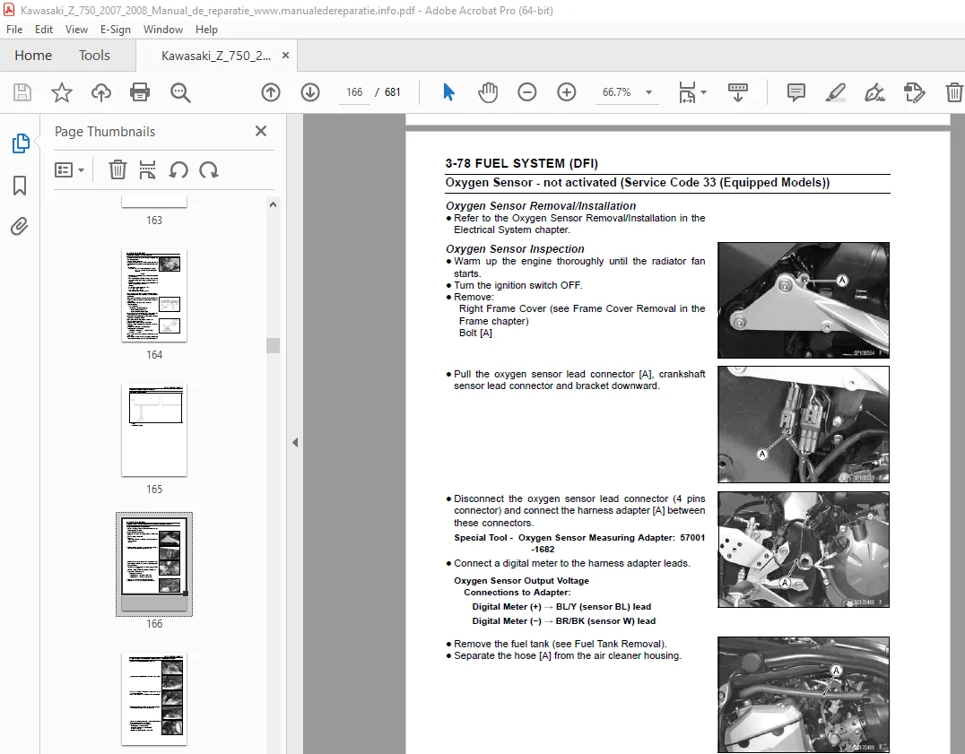
Oxygen Sensor Removal/Installation 166
Oxygen Sensor Inspection 166
Special Tool – 166
Special Tool – 167
Oxygen Sensor Circuit 169
Exhaust Butterfly Valve Actuator Sensor Removal/Installation 170
Exhaust Butterfly Valve Actuator Sensor Input Voltage Inspection 170
Special Tool – 170
Exhaust Butterfly Valve Actuator Sensor Output Voltage Inspectio 171
Special Tool – 171
Exhaust Butterfly Valve Actuator Sensor Resistance Inspection 172
Exhaust Butterfly Valve Actuator Sensor Circuit 172
Antenna Resistance Inspection 173
Amplifier Input Voltage Inspection 173
Special Tool – 173
User Key Inspection 174
Immobilizer System Circuit 174
ECU Communication Line Inspection 175
ECU Communication Line Circuit 175
Stick Coil ##1: Service Code 51 176
Stick Coil Removal/Installation 176
Stick Coil Primary Winding Resistance Inspection 176
Stick Coil Input Voltage Inspection 176
Special Tool – 176
Stick Coil Circuit 177
Radiator Fan Relay Removal/Installation 178
Radiator Fan Relay Inspection 178
Radiator Fan Relay Circuit 178
Subthrottle Valve Actuator Removal 179
Subthrottle Valve Actuator Inspection 179
Subthrottle Valve Actuator Resistance Inspection 179
Subthrottle Valve Actuator Input Voltage Inspection 180
Special Tool – 180
Special Tool – 180
Subthrottle Valve Actuator Circuit 181
Exhaust Butterfly Valve Actuator Removal 182
Exhaust Butterfly Valve Actuator Installation 183
Torque – 183
Torque – 184
Torque – 184
Exhaust Butterfly Valve Actuator Inspection 184
Exhaust Butterfly Valve Actuator Resistance Inspection 184
Special Tool – 184
Exhaust Butterfly Valve Actuator Circuit 185
Air Switching Valve Removal/Installation 186
Air Switching Valve Inspection 186
Air Switching Valve Circuit 186
Oxygen Sensor Heater Removal/Installation 187
Oxygen Sensor Heater Resistance Inspection 187
Oxygen Sensor Heater Power Source Voltage Inspection 188
Special Tool – 188
Oxygen Sensor Circuit 189
Oxygen Sensor Removal/Installation 190
Oxygen Sensor Inspection 190
Special Tool – 190
Special Tool – 191
Oxygen Sensor Circuit 192
Light (LED) Inspection 193
Warning Indicator Light (LED) (FI/Immobilizer) Circuit 193
ECU Identification 194
ECU Removal 194
ECU Installation 195
ECU Power Supply Inspection 195
Special Tool – 195
Special Tool – 196
ECU Power Source Circuit 197
ECU Fuse Removal 198
ECU Fuse Installation 198
ECU Fuse Inspection 198
ECU Main Relay Removal/Installation 198
ECU Main Relay Inspection 198
Fuel Pressure Inspection 199
Special Tools – 199
Fuel Flow Rate Inspection 200
Special Tool – 200
Fuel Pump Removal 202
Fuel Pump Installation 203
Torque – 203
Fuel Pump Operation Inspection 203
Fuel Pump Operating Voltage Inspection 204
Special Tool – 204
Pressure Regulator Removal 205
Pump Screen, Fuel Filter Cleaning 205
Fuel Pump Relay Removal/Installation 205
Fuel Pump Relay Inspection 205
Fuel Pump Circuit 206
Fuel Injector Removal/Installation 207
Fuel Injector Audible Inspection 207
Fuel Injector Resistance Inspection 207
Fuel Injector Power Source Voltage Inspection 208
Special Tool – 208
Fuel Injector Output Voltage Inspection 209
Special Tool – 209
Fuel Injector Fuel Line Inspection 210
Fuel Injector Circuit 211
Free Play Inspection 212
Free Play Adjustment 212
Cable Installation 212
Cable Lubrication 212
Idle Speed Inspection/Adjustment 213
Synchronization Inspection/Adjustment 213
Throttle Body Assy Removal 213
Throttle Body Assy Installation 216
Torque – 216
Torque – 216
Torque – 217
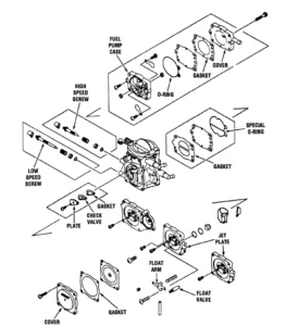
Throttle Body Assy Disassembly 217
Throttle Body Assy Assembly 218
Torque – 219
Air Cleaner Element Removal/Installation 220
Air Cleaner Element Inspection 220
Air Cleaner Oil Draining 220
Air Cleaner Housing Removal 220
Fuel Tank Removal 221
Fuel Tank Installation 223
Fuel Tank Inspection 224
Fuel Tank Cleaning 224
Cooling System 225
Bearing Driver Set: 231
Coolant Deterioration Inspection 232
Coolant Level Inspection 232
Coolant Draining 232
Coolant Filling 232
Pressure Testing 232
Cooling System Flushing 233
Coolant Reserve Tank Removal/Installation 233
Water Pump Removal 234
Water Pump Installation 234
Water Pump Inspection 234
Water Pump Impeller Disassembly/Assembly 234
Water Pump Impeller Inspection 234
Water Pump Housing Disassembly 234
Water Pump Housing Assembly 235
Special Tool – 235
Special Tool – 235
Mechanical Seal Inspection 235
Radiator and Radiator Fan Removal 236
Radiator and Radiator Fan Installation 237
Torque – 237
Radiator Inspection 237
Radiator Cap Inspection 238
Radiator Filler Neck Inspection 238
Thermostat Removal 239
Thermostat Installation 239
Torque – 239
Torque – 239
Thermostat Inspection 240
Hose Installation 241
Torque – 241
Hose Inspection 241
CAUTION 242
Water Temperature Sensor Removal/Installation 242
Water Temperature Sensor Inspection 242
Engine Top End 243
Exhaust System 248
Compression Gauge, 20 kgf/cm : 252
Air Suction Valve Removal 254
Air Suction Valve Installation 254
Torque – 254
Air Suction Valve Inspection 254
Air Switching Valve Removal 255
Air Switching Valve Installation 255
Air Switching Valve Operation Test 255
Air Switching Valve Unit Test 255
Clean Air System Hose Inspection 255
Cylinder Head Cover Removal 256
Cylinder Head Cover Installation 256
Sealant – 256
Torque – 256
Camshaft Chain Tensioner Removal 257
Camshaft Chain Tensioner Installation 257
Torque – 257
Torque – 257
Camshaft Removal 258
Camshaft Installation 258
Torque – 259
Camshaft, Camshaft Cap Wear 259
Camshaft Runout 260
Cam Wear 260
Camshaft Chain Removal 260
Cylinder Compression Measurement 261
Special Tools – 261
Torque – 261
Cylinder Head Removal 262
Cylinder Head Installation 262
Torque – 262
Torque – 263
Cylinder Head Warp 263
Valve Clearance Inspection 264
Valve Clearance Adjustment 264
Valve Removal 264
Special Tools – 264
Valve Installation 264
Valve Guide Removal 264
Special Tool – 264
Valve Guide Installation 265
Special Tool – 265
Special Tool – 265
Valve-to-Guide Clearance Measurement (Wobble Method) 265
Valve Seat Inspection 266
Valve Seat Repair 266
Special Tools – 266
Cylinder Removal 271
Cylinder Installation 271
Piston Removal 272
Special Tool – 272
Piston Installation 272
Cylinder Wear 273
Piston Wear 273
Piston Ring, Piston Ring Groove Wear 274
Piston Ring Groove Width 274
Piston Ring Thickness 274
Piston Ring End Gap 275
Throttle Body Holder Installation 276
Torque – 276
WARNING 277
Muffler Body Removal 277
Muffler Body Installation 278
Torque – 278
Exhaust Pipe Removal 279
Exhaust Pipe Installation 280
Torque – 280
Exhaust Butterfly Valve Cable Removal 281
Exhaust Butterfly Valve Cable Installation 282
Torque – 282
Torque – 285
Clutch 287
Clutch Holder: 291
Clutch Lever Free Play Inspection 292
Clutch Lever Free Play Adjustment 292
Clutch Cable Removal 292
Clutch Cable Installation 292
Clutch Cable Lubrication 292
Clutch Lever Installation 292
Torque – 292
Clutch Cover Removal 293
Clutch Cover Installation 293
Sealant – 293
Torque – 293
Release Shaft Removal 293
Release Shaft Installation 293
Clutch Cover Disassembly 294
Clutch Cover Assembly 294
Clutch Removal 295
Special Tool – 295
Clutch Installation 295
Special Tool – 296
Torque – 296
Torque – 297
Clutch Plate Assembly Inspection 297
Torque – 297
Clutch Plate Assembly Adjustment 297
Torque – 297
Clutch Plate, Wear, Damage Inspection 298
Clutch Plate Warp Inspection 298
Clutch Spring Free Length Measurement 298
Engine Lubrication System 299
Outside Circlip Pliers: 304
WARNING 305
Oil Level Inspection 305
Engine Oil Change 305
Oil Filter Replacement 305
Oil Pan Removal 306
Oil Pan Installation 306
Torque – 306
Torque – 306
Oil Pressure Relief Valve Removal 307
Oil Pressure Relief Valve Installation 307
Oil Pressure Relief Valve Inspection 307
Oil Pump Removal 308
Oil Pump Installation 308
Torque – 309
Torque – 309
Torque – 309
Oil Pump Drive Gear Removal 309
Special Tool – 309
Oil Pump Drive Gear Installation 309
Special Tool – 309
Oil Pressure Measurement 310
Special Tools – 310
Torque – 310
Oil Pressure Switch Removal 311
Oil Pressure Switch Installation 311
Sealant – 311
Torque – 311
Torque – 311
Engine Removal/Installation 313
Engine Mount Nut Wrench: 316
Engine Removal 317
Special Tool – 319
Engine Installation 319
Torque – 320
Torque – 320
Torque – 321
Crankshaft/Transmission 323
Bearing Puller: 330
Crankcase Splitting 331
Crankcase Assembly 331
Sealant – 332
Torque – 332
Torque – 333
Sealant – 333
Torque – 334
Torque – 334
Torque – 334
Torque – 334
Crankshaft Removal 335
Crankshaft Installation 335
Connecting Rod Removal 335
Connecting Rod Installation 335
Crankshaft/Connecting Rod Cleaning 338
Connecting Rod Bend 339
Connecting Rod Twist 339
Connecting Rod Big End Side Clearance 339
Connecting Rod Big End Bearing Insert/Crankpin Wear 340
Crankshaft Side Clearance 341
Crankshaft Runout 342
Crankshaft Main Bearing Insert/Journal Wear 342
Starter Motor Clutch Removal/Installation 344
Starter Motor Clutch Inspection 344
Starter Motor Clutch Disassembly 344
Starter Motor Clutch Assembly 344
Torque – 344
Shift Pedal Removal 345
Shift Pedal Installation 345
Torque – 345
Torque – 346
Torque – 346
Torque – 346
External Shift Mechanism Removal 346
External Shift Mechanism Installation 347
Torque – 347
Torque – 347
External Shift Mechanism Inspection 347
Torque – 347
Transmission Shaft Removal 348
Transmission Shaft Installation 348
Transmission Shaft Disassembly 348
Special Tool – 348
Special Tools – 349
Transmission Shaft Assembly 349
Shift Drum and Fork Removal 352
Shift Drum and Fork Installation 352
Torque – 352
Shift Drum Disassembly 352
Shift Drum Assembly 352
Torque – 352
Shift Fork Bending 353
Shift Fork/Gear Groove Wear 353
Shift Fork Guide Pin/Drum Groove Wear 353
Gear Dog and Gear Dog Hole Damage 353
Wheels/Tires 355
Bearing Driver Set: 359
Front Wheel Removal 360
Special Tools – 360
Front Wheel Installation 360
Torque – 361
Torque – 361
Rear Wheel Removal 361
Rear Wheel Installation 362
Torque – 362
Wheel Inspection 364
Special Tools – 364
Axle Inspection 364
Balance Inspection 365
Balance Adjustment 365
Balance Weight Removal 365
Balance Weight Installation 365
Air Pressure Inspection/Adjustment 367
Tire Inspection 367
Tire Removal 367
Tire Installation 367
Tire Repair 369
Hub Bearing Removal 370
Special Tools – 370
Hub Bearing Installation 370
Special Tool – 370
Special Tool – 371
Hub Bearing Inspection 371
Hub Bearing Lubrication 371
Final Drive 373
Inside Circlip Pliers: 377
Drive Chain Slack Inspection 378
Drive Chain Slack Adjustment 378
Wheel Alignment Inspection/Adjustment 378
Drive Chain Wear Inspection 378
Drive Chain Lubrication 378
Drive Chain Removal 378
Drive Chain Installation 378
Drive Chain Replacement 378
Recommended Tool – 379
Engine Sprocket Removal 382
Engine Sprocket Installation 382
Torque – 382
Torque – 383
Rear Sprocket Removal 383
Rear Sprocket Installation 383
Torque – 383
Coupling Installation 383
Coupling Bearing Removal 384
Special Tool – 384
Special Tool – 384
Coupling Bearing Installation 384
Special Tool – 384
Special Tool – 384
Special Tool – 384
Coupling Bearing Inspection 385
Coupling Bearing Lubrication 385
Coupling Damper Inspection 385
Sprocket Wear Inspection 385
Rear Sprocket Warp Inspection 386
Brakes 387
ABS Equipped Models 394
ABS Equipped Models 396
Inside Circlip Pliers: 399
Brake Lever Position Adjustment 400
Brake Pedal Position Inspection 400
Brake Pedal Position Adjustment 400
Torque – 400
Brake Pedal Removal 400
Brake Pedal Installation 401
Torque – 401
Torque – 401
Front Caliper Removal 402
Rear Caliper Removal 402
Caliper Installation 402
Torque – 403
Front Caliper Disassembly 403
Front Caliper Assembly 403
Rear Caliper Disassembly 403
Rear Caliper Assembly 403
Caliper Fluid Seal Damage 404
Caliper Dust Seal Damage 404
Front Caliper Dust Boot and Friction Boot Damage 404
Caliper Piston and Cylinder Damage 405
Front Caliper Holder Shaft Wear 405
Front Brake Pad Removal 406
Front Brake Pad Installation 406
Torque – 406
Rear Brake Pad Removal 407
Rear Brake Pad Installation 407
Torque – 407
Brake Pad Wear Inspection 408
Front Master Cylinder Removal 409
Front Master Cylinder Installation 409
Torque – 409
Torque – 409
Rear Master Cylinder Removal 409
Rear Master Cylinder Installation 410
Torque – 410
Front Master Cylinder Disassembly 410
Rear Master Cylinder Disassembly 410
Master Cylinder Assembly 410
Master Cylinder Inspection (Visual Inspection) 410
Brake Disc Removal 411
Brake Disc Installation 411
Torque – 411
Brake Disc Wear 411
Brake Disc Warp 411
Special Tools – 411
Brake Fluid Level Inspection 412
Brake Fluid Change 412
Brake Line Bleeding 412
Torque – 413
Torque – 413
Brake Hose and Pipe Removal/Installation 415
Brake Hose and Pipe Inspection 415
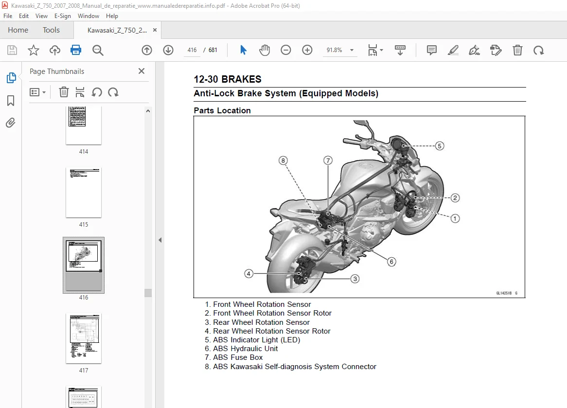
Parts Location 416
ABS System Wiring Diagram 417
Terminal Names 418
ABS Servicing Precautions 419
ABS Troubleshooting Outline 421
Special Tool – 421
Special Tool – 422
ABS Diagnosis Flow Chart 423
Inquiries to Rider 424
Pre-Diagnosis Inspection 1 425
Pre-Diagnosis Inspection 2 426
Self-diagnosis Outline 426
Self-diagnosis Procedures 426
Service Code Clearing Procedures 427
Self-diagnosis Flow Chart 429
How to Read Service Codes 430
How to Erase Service Codes 430
ABS Indicator Light (LED) Inspection 432
ABS Indicator Light (LED) is Unlit (When the Ignition Switch tur 432
Special Tool – 432
ABS Indicator Light (LED) Lights (When the Motorcycle is Running 433
Special Tool – 433
Solenoid Valve Inspection (Service Code 13,14,17,18) 433
ABS Solenoid Valve Relay Inspection (Service Code 19) 433
Special Tool – 434
Front, Rear Wheel Rotation Difference Abnormal (Service Code 25) 435
ABS Pump Motor Relay Inspection (Service Code 35) 435
Special Tool – 436
Front Wheel Rotation Sensor Signal Abnormal (Service Code 42) 436
Front Wheel Rotation Sensor Wiring Inspection (Service Code 43) 437
Rear Wheel Rotation Sensor Signal Abnormal (Service Code 44) 438
Rear Wheel Rotation Sensor Wiring Inspection (Service Code 45) 439
Power Supply Voltage Abnormal (Under-Voltage) (Service Code 52) 439
Special Tool – 440
Power Supply Voltage Abnormal (Over-Voltage) (Service Code 53) 440
Special Tool – 441
ECU Inspection (Service Code 55) 441
ABS Hydraulic Unit Removal 441
ABS Hydraulic Unit Installation 443
Torque – 443
ABS Hydraulic Unit Inspection 443
Front Wheel Rotation Sensor Removal 444
Front Wheel Rotation Sensor Installation 444
Rear Wheel Rotation Sensor Removal 445
Rear Wheel Rotation Sensor Installation 445
Wheel Rotation Sensor Inspection 446
Wheel Rotation Sensor Air Gap Inspection 446
Wheel Rotation Sensor Rotor Inspection 447
ABS Solenoid Valve Relay Fuse (20 A) Removal 447
ABS Motor Relay Fuse (30 A) Removal 447
ABS ECU Fuse (10 A) Removal 447
Fuse Installation 448
Fuse Inspection 448
Suspension 449
Inside Circlip Pliers: 455
Rebound Damping Force Adjustment 457
Spring Preload Adjustment 457
Front Fork Removal (Each Fork Leg) 458
Front Fork Installation 458
Torque – 458
Front Fork Oil Change 458
Special Tool – 459
Special Tool – 459
Special Tool – 460
Special Tool – 460
Special Tool – 461
Special Tool – 462
Special Tool – 462
Special Tool – 462
Torque – 463
Front Fork Disassembly 463
Special Tool – 463
Front Fork Assembly 464
Special Tool – 464
Torque – 464
Special Tool – 464
Inner Tube, Outer Tube Inspection 465
Dust Seal Inspection 465
Spring Tension Inspection 465
Rebound Damping Force Adjustment 466
Spring Preload Adjustment 466
Spring Preload Adjustment 466
Special Tool – 466
Rear Shock Absorber Removal 467
Special Tools – 467
Rear Shock Absorber Installation 467
Torque – 467
Rear Shock Absorber Inspection 467
Swingarm Removal 468
Special Tools – 468
Special Tool – 468
Swingarm Installation 469
Torque – 469
Special Tool – 469
Torque – 469
Torque – 469
Swingarm Bearing Removal 470
Special Tool – 470
Special Tool – 470
Swingarm Bearing Installation 470
Special Tools – 470
Swingarm Bearing, Sleeve Inspection 471
Swingarm Bearing Lubrication 472
Chain Guide Inspection 472
Tie-Rod Removal 473
Special Tools – 473
Tie-Rod Installation 473
Torque – 473
Rocker Arm Removal 473
Special Tools – 473
Rocker Arm Installation 473
Torque – 473
Tie-Rod and Rocker Arm Bearing Removal 474
Special Tools – 474
Tie-Rod and Rocker Arm Bearing Installation 474
Special Tools – 474
Rocker Arm/Tie-Rod Bearing, Sleeve Inspection 475
Rocker Arm/Tie-Rod Bearing Lubrication 475
Steering 477
Head Pipe Outer Race Press Shaft: 480
Steering Inspection 481
Steering Adjustment 481
Stem, Stem Bearing Removal 482
Special Tool – 482
Special Tool – 482
Stem, Stem Bearing Installation 483
Special Tools – 483
Special Tools – 483
Special Tool – 484
Torque – 484
Torque – 484
Steering Stem Bearing Lubrication 484
Steering Stem Warp 485
Stem Cap Deterioration, Damage 485
Handlebar Removal 486
Handlebar Installation 486
Torque – 486
Torque – 487
Torque – 487
Torque – 487
Frame 489
Rear Seat Removal 495
Rear Seat Installation 495
Front Seat Removal 495
Front Seat Installation 495
Center Fairing Removal 496
Center Fairing Installation 496
Upper Fairing Removal 496
Upper Fairing Disassembly 496
Upper Fairing Assembly 496
Upper Fairing Installation 497
Inner Cover Removal 497
Inner Cover Installation 497
Upper Fairing Bracket Removal 497
Upper Fairing Bracket Installation 497
Inner Fairing Removal 497
Inner Fairing Installation 497
Sub Side Cover Removal 498
Sub Side Cover Installation 498
Side Cover Removal 498
Side Cover Installation 498
Seat Cover Removal 499
Seat Cover Installation 500
Front Fender Removal 501
Front Fender Installation 501
Torque – 501
Flap and Rear Fender Removal 501
Flap and Rear Fender Installation 501
Frame Inspection 502
Sidestand Removal 503
Sidestand Installation 503
Torque – 503
Torque – 503
Frame Cover Removal 504
Frame Cover Installation 504
Rear View Mirrors Removal 505
Rear View Mirrors Installation 505
Electrical System 507
Dummy Page 509
Hand Tester: 517
Dummy Page 519
There are a number of important precautions that are musts when 526
Wiring Inspection 527
Special Tool – 527
Battery Removal 528
Battery Installation 528
Battery Activation 529
Precautions 532
1) 532
2) 532
3) 532
4) 532
Interchange 532
Charging Condition Inspection 532
Refreshing Charge 533
Alternator Cover Removal 534
Alternator Cover Installation 535
Sealant – 535
Torque – 535
Stator Coil Removal 535
Stator Coil Installation 536
Torque – 536
Torque – 536
Sealant – 536
Alternator Rotor Removal 536
Special Tools – 536
Special Tool – 536
Alternator Rotor Installation 537
Special Tools – 538
Special Tool – 538
Special Tools – 538
Torque – 538
Alternator Inspection 538
Special Tool – 539
Regulator/Rectifier Inspection 540
Charging Voltage Inspection 542
Special Tool – 542
Charging System Circuit 543
WARNING 544
Crankshaft Sensor Removal 544
Crankshaft Sensor Installation 545
Torque – 545
Sealant – 545
Torque – 545
Torque – 546
Crankshaft Sensor Inspection 546
Special Tool – 546
Crankshaft Sensor Peak Voltage Inspection 547
Special Tools – 547
Timing Rotor Removal 547
Special Tool – 547
Timing Rotor Installation 547
Torque – 547
Camshaft Position Sensor Removal 548
Camshaft Position Sensor Installation 548
Torque – 548
Camshaft Position Sensor Inspection 549
Special Tool – 549
Camshaft Position Sensor Peak Voltage Inspection 549
Special Tools – 549
Stick Coil Removal 550
Stick Coil Installation 550
Stick Coil Inspection 551
Stick Coil Primary Peak Voltage 551
Special Tools – 551
Spark Plug Removal 552
Spark Plug Installation 552
Spark Plug Condition Inspection 552
Interlock Operation Inspection 552
IC Igniter Inspection 553
Ignition System Circuit 555
Starter Motor Removal 556
Starter Motor Installation 556
Torque – 556
Starter Motor Disassembly 557
Starter Motor Assembly 557
Brush Inspection 558
Commutator Cleaning and Inspection 559
Armature Inspection 559
Special Tool – 559
Brush Lead Inspection 559
Special Tool – 559
Brush Plate and Terminal Bolt Inspection 560
Special Tool – 560
Starter Relay Inspection 560
Special Tool – 560
Electric Starter Circuit 561
This motorcycle adopt the daylight system and have a headlight r 562
Headlight Beam Horizontal Adjustment 562
Headlight Beam Vertical Adjustment 562
Headlight Bulb Replacement 562
Headlight Removal/Installation 563
City Light Bulb Replacement 564
Tail/Brake Light (LED) Removal 565
Tail/Brake Light (LED) Installation 565
Torque – 565
License Plate Light Bulb Replacement 565
Torque – 565
Headlight/Tail Light Circuit 566
Turn Signal Light Bulb Replacement 566
Turn Signal Relay Inspection 567
Turn Signal Light Circuit 568
Air Switching Valve Operation Test 569
Air Switching Valve Unit Test 569
Special Tool – 569
Air Switching Valve Circuit 570
Fan Motor Inspection 571
Radiator Fan Circuit 571
Meter Unit Removal/Installation 572
Torque – 572
Meter, Gauge Disassembly 572
Electronic Combination Meter Unit Inspection 573
Fuel Level Sensor Line Self-Diagnosis Mode Inspection 584
Meter Circuit 585
This motorcycle is equipped with an immobilizer system to protec 586
Operational Cautions 586
Key Registration 586
Special Tools – 586
Spare User Key Registration Flow Chart 591
Special Tools – 592
All Keys Initial Registration Flow Chart 601
Immobilizer System Parts Replacement 602
Immobilizer System Inspection 605
Immobilizer System Circuit 606
Brake Light Timing Inspection 607
Brake Light Timing Adjustment 607
Switch Inspection 607
Special Tool – 607
Rear Brake Light Switch Connections 607
Sidestand Switch Connections 607
Neutral Switch Connections 607
Oil Pressure Switch Connections * 607
Water Temperature Sensor Inspection 608
Speed Sensor Removal 608
Speed Sensor Installation 609
Torque – 609
Speed Sensor Inspection 609
Oxygen Sensor Removal (Equipped Models) 609
Oxygen Sensor Installation (Equipped Models) 610
Torque – 610
Oxygen Sensor Inspection (Equipped Models) 610
Fuel Level Sensor Inspection 610
Special Tool – 610
Torque – 611
The relay box [A] has relays and diodes The relays and diodes c 612
Relay Box Removal 612
Relay Circuit Inspection 612
Diode Circuit Inspection 613
Relay Box Internal Circuit 614
30 A Main Fuse Removal 615
Fuse Box Fuse Removal 615
10 A ECU Fuse Removal 616
Fuse Installation 616
Fuse Inspection 616
Appendix 617
ABS Equipped Models 662
ABS Equipped Models 664
ABS Equipped Models 666
ABS Equipped Models 668
ABS Equipped Models 670
ABS Equipped Models 672
ABS Equipped Models 674
NOTE 676
Engine Doesn’t Start, Starting Difficulty: 676
Starter motor not rotating: 676
Starter motor rotating but engine doesn’t turn over: 676
Engine won’t turn over: 676
No fuel flow: 676
No spark; spark weak: 676
Fuel/air mixture incorrect: 676
Compression Low: 676
Poor Running at Low Speed: 676
Spark weak: 676
Fuel/air mixture incorrect: 676
Compression low: 677
Run-on (dieseling): 677
Other: 677
Poor Running or No Power at High Speed: 677
Firing incorrect: 677
Fuel/air mixture incorrect: 677
Compression low: 677
Knocking: 677
Miscellaneous: 677
Overheating: 677
Firing incorrect: 677
Muffler overheating: 677
Fuel/air mixture incorrect: 677
Compression high: 678
Engine load faulty: 678
Lubrication inadequate: 678
Gauge incorrect: 678
Coolant incorrect: 678
Cooling system component incorrect: 678
Over Cooling: 678
Gauge incorrect: 678
Cooling system component incorrect: 678
Clutch Operation Faulty: 678
Clutch slipping: 678
Clutch not disengaging properly: 678
Gear Shifting Faulty: 678
Doesn’t go into gear; shift pedal doesn’t return: 678
Jumps out of gear: 678
Overshifts: 678
Abnormal Engine Noise: 678
Knocking: 678
Piston slap: 678
Valve noise: 678
Other noise: 678
Abnormal Drive Train Noise: 679
Clutch noise: 679
Transmission noise: 679
Drive line noise: 679
Abnormal Frame Noise: 679
Front fork noise: 679
Rear shock absorber noise: 679
Disc brake noise: 679
Other noise: 679
Oil Pressure Warning Light Goes On: 679
Exhaust Smokes Excessively: 679
White smoke: 679
Black smoke: 679
Brown smoke: 679
Handling and/or Stability Unsatisfactory: 679
Handlebar hard to turn: 679
Handlebar shakes or excessively vibrates: 679
Handlebar pulls to one side: 679
Shock absorption unsatisfactory: 679
Brake Doesn’t Hold: 680
Battery Trouble: 680
Battery discharged: 680
Battery overcharged: 680
tables 1
COUNTRY AND AREA CODES 6
Units of Mass: 20
Units of Volume: 20
Units of Force: 20
Units of Length: 20
Units of Torque: 20
Units of Pressure: 20
Units of Speed: 20
Units of Power: 20
Periodic Inspection 23
Periodic Replacement Parts 25
Basic Torque for General Fasteners 31
Throttle Grip Free Play 35
Idle Speed 37
Throttle Body Vacuum 37
Main Throttle Sensor Output Voltage 39
Idle Speed 39
Valve Clearance 43
Adjustment Shims 44
Clutch Lever Free Play 51
Air Pressure (when Cold) 52
Tread Depth 53
Chain Slack 55
Drive Chain 20-link Length 57
Standard Chain 57
Recommended Disc Brake Fluid 60
Pad Lining Thickness 60
Sidestand Switch Operation 69
Water and Coolant Mixture Ratio (Recommended) 77
Recommended Engine Oil 79
Standard Spark Plug 87
Sample Diagnosis Sheet 117
Engine Won’t Turn Over 119
Poor Running at Low Speed 119
Poor Running or No Power at High Speed: 122
Main Throttle Sensor Input Voltage 133
Input Voltage 133
Wiring Inspection 134
Main Throttle Sensor Output Voltage 134
Idle Speed 134
Output Voltage 135
Wiring Inspection 135
Main Throttle Sensor Resistance 135
Inlet Air Pressure Sensor Input Voltage 137
Input Voltage 137
Wiring Inspection 138
Inlet Air Pressure Sensor Output Voltage 138
Output Voltage 138
Wiring Inspection 138
Inlet Air Pressure Sensor Output Voltage 139
Inlet Air Temperature Sensor Output Voltage 142
Output Voltage 142
Wiring Inspection 143
Inlet Air Temperature Sensor Resistance 143
Water Temperature Sensor Output Voltage 145
Output Voltage 145
Wiring Inspection 146
Atmospheric Pressure Sensor Input Voltage 147
Input Voltage 147
Wiring Inspection 148
Atmospheric Pressure Sensor Output Voltage 148
Output Voltage 148
Wiring Inspection 148
Wiring Inspection 152
Wiring Inspection 153
Speed Sensor Input Voltage 155
Input Voltage 155
Wiring Inspection 155
Speed Sensor Output Voltage 156
Output Voltage 156
Wiring Inspection 156
Vehicle-down Sensor Input Voltage 159
Input Voltage 159
Wiring Inspection 159
Vehicle-down Sensor Output Voltage 160
Output Voltage 160
Wiring Inspection 161
Subthrottle Sensor Input Voltage 162
Input Voltage 162
Wiring Inspection 163
Subthrottle Sensor Output Voltage 163
Output Voltage 164
Wiring Inspection 164
Subthrottle Sensor Resistance 164
Oxygen Sensor Output Voltage 166
Output Voltage (with Plugs) 168
Output Voltage (without Plugs) 168
Wiring Inspection 168
Exhaust Butterfly Valve Actuator Sensor Input Voltage 170
Input Voltage 170
Wiring Inspection 170
Exhaust Butterfly Valve Actuator Sensor Output Voltage 171
Output Voltage 171
Wiring Inspection 171
Exhaust Butterfly Valve Actuator Sensor Resistance 172
Antenna Resistance 173
Amplifier Input Voltage 173
Wiring Inspection 175
Stick Coil Input Voltage 176
Input Voltage 176
Subthrottle Valve Actuator Resistance 179
Subthrottle Valve Actuator Input Voltage 180
Input Voltage 180
Wiring Inspection 180
Exhaust Butterfly Valve Actuator Resistance 184
Wiring Inspection 185
Oxygen Sensor Heater Resistance 187
Oxygen Sensor Power Source Voltage 188
Power Source Voltage 188
Wiring Inspection 188
Oxygen Sensor Output Voltage 190
Output Voltage (with Plugs) 192
Output Voltage (without Plugs) 192
ECU Identification 194
ECU Grounding Inspection 195
ECU Power Supply Inspection 196
Fuel Pressure (with Engine Iding) 199
Amount of Fuel Flow 201
Fuel Pump Operating Voltage 204
Operating Voltage 204
Fuel Injector Resistance 207
Fuel Injector Power Source Voltage 208
Power Source Voltage 208
Fuel Injector Output Voltage 209
Output Voltage 209
Wiring Inspection 210
Injector Fuel Line Maximum Pressure 210
Radiator Cap Relief Pressure 238
Thermostat Valve Opening Temperature 240
Camshaft Journal, Camshaft Cap Clearance 259
Camshaft Journal Diameter 260
Camshaft Runout 260
Cam Height 260
Cylinder Compression 261
Cylinder Head Warp 263
Valve/Valve Guide Clearance (Wobble Method) 265
Valve Seating Surface Outside Diameter 266
Valve Seating Surface Width 266
Cylinder Inside Diameter 273
Piston Diameter 273
Piston Ring/Groove Clearance 274
Piston Ring Groove Width 274
Piston Ring Thickness 274
Piston Ring End Gap 275
Clutch Plate Assembly Length 297
Friction Plate Thickness 298
Friction and Steel Plate Warp 298
Clutch Spring Free Length 298
Oil Pressure 310
Connecting Rod Bend 339
Connecting Rod Twist 339
Connecting Rod Big End Side Clearance 339
Connecting Rod Big End Bearing Insert/Crankpin Clearance 340
Crankpin Diameter 340
Crankpin Diameter Marks 340
Connecting Rod Big End Inside Diameter Marks 341
Crankshaft Side Clearance 341
Crankshaft Runout 342
Crankshaft Main Bearing Insert/Journal Clearance 342
Crankshaft Main Journal Diameter 342
Crankshaft Main Journal Diameter Marks 342
Crankcase Main Bearing Inside Diameter Marks 343
Shift Fork Ear Thickness 353
Gear Groove Width 353
Shift Fork Guide Pin Diameter 353
Shift Drum Groove Width 353
Rim Runout (with tire installed) 364
Axle Runout/100 mm (3 94 in ) 364
Balance Weight 366
Link Pin Outside Diameter 381
Link Plates Outside Width 381
Rear Sprocket Warp 386
Pedal Position 400
Brake Discs Thickness 411
Disc Runout 411
Sample Diagnosis Sheet 424
Service Code Table 431
Terminal Voltage 432
Battery Terminal Voltage 434
Battery Terminal Voltage 436
Air Gap 436
Air Gap 438
Battery Terminal Voltage 440
Battery Terminal Voltage 441
Air Gap 446
Rebound Damping Force Adjustment 457
Adjuster Protrusion (from top) 457
Spring Action 457
Fork Oil 460
Oil Level (fully compressed, without spring) 461
Spring Free Length 465
Rebound Damping Force Adjustment 466
Spring Preload Setting 466
Spring Preload Adjustment 466
Kawasaki-recommended chargers: 531
Battery Terminal Voltage 533
Terminal Voltage: 11 5 ∼ less than 12 8 V 533
Terminal Voltage: less than 11 5 V 533
Table 1 Alternator Output Voltage at 4 000 r/min (rpm) 539
Table 2 Stator Coil Resistance at 20°C (68°F) 539
Rectifier Circuit Inspection 540
Charging Voltage 542
Connections: 547
Crankshaft Sensor Peak Voltage 547
Camshaft Position Sensor Resistance: 549
Connections: 549
Camshaft Position Sensor Peak Voltage 549
Stick Coil Winding Resistance 551
Primary Lead Connection 551
Stick Coil Primary Peak Voltage 552
Condition: 552
Condition: 553
Condition: 553
Starter Motor Brush Length [D] 558
Commutator Diameter 559
Testing Relay 560
Testing Turn Signal Relay 567
Air Switching Valve Resistance 569
User Key Indicator Flashes 589
Water Temperature Sensor 608
Fuel Level Sensor Resistance 610
Relay Circuit Inspection (with the battery disconnected) 612
Relay Circuit Inspection (with the battery connected) 613
Diode Circuit Inspection 613
DESCRIPTION:
Kawasaki Z750 Z750 ABS Motorcycle Service Manual – PDF DOWNLOAD
FOREWORD:
- This manual is designed primarily for use by trained mechanics in a properly equipped shop. However, it contains enough detail and basic information to make it useful to the owner who desires to perform his own basic maintenance andrepair work. A basic knowledge of mechanics, the proper use of tools, and workshop procedures must be understood in order to carry outmaintenance and repair satisfactorily. Whenever the owner has insufficient experience or doubts his ability to do the work, all adjustments, maintenance, and repair should be carried out only by qualified mechanics.
- In order to perform the work efficiently and to avoid costly mistakes, read the text, thoroughly familiarize yourself with the procedures before starting work, and then do the work carefullyin a clean area. Whenever special tools or equipment are specified, do not use makeshift tools or equipment. Precision measurements can only be made if the proper instruments are used, and the use of substitute tools may adversely affect safe operation.
- For the duration of the warranty period, we recommend that all repairs and scheduled maintenance be performed in accordance with this servicemanual. Any owner maintenance or repair procedure not performed in accordance with this manual may void the warranty.
To get the longest life out of your vehicle:
S.V 17/03/2025