Kawasaki ZZR 1400 ZZR1400 ABS Ninja ZX-14 Motorcycle Service Manual PDF
$32.95
Kawasaki ZZR 1400 ZZR1400 ABS Ninja ZX-14 Motorcycle Service Manual – PDF DOWNLOAD
Description
Kawasaki ZZR 1400 ZZR1400 ABS Ninja ZX-14 Motorcycle Service Manual – PDF DOWNLOAD
FILE DETAILS:
Kawasaki ZZR 1400 ZZR1400 ABS Ninja ZX-14 Motorcycle Service Manual – PDF DOWNLOAD
Language : English
Pages : 704
Downloadable : Yes
File Type : PDF
IMAGES PREVIEW OF THE MANUAL:
TABLE OF CONTENTS:
Kawasaki ZZR 1400 ZZR1400 ABS Ninja ZX-14 Motorcycle Service Manual – PDF DOWNLOAD
ZZR1400_’ABS’_&_ZX-14_(ZX1400-A6F_&_B6F)_SM_2006_ pdf 0
ZZR1400_’ABS’_&_ZX-14_(ZX1400-A6F_&_B6F)_SM_2006_ pdf 0
Cover 2
Quick Reference Guide 4
1 General Information 12
Before starting to perform an inspection service or carry out a 13
Battery Ground 13
Edges of Parts 13
Solvent 13
Cleaning vehicle before disassembly 13
Arrangement and Cleaning of Removed Parts 14
Storage of Removed Parts 14
Inspection 14
Replacement Parts 14
Assembly Order 14
Tightening Sequence 15
Tightening Torque 15
Force 15
Gasket, O-ring 15
Liquid Gasket, Non-permanent Locking Agent 15
Press 16
Ball Bearing and Needle Bearing 16
Oil Seal, Grease Seal 16
Circlips, Cotter Pins 16
Lubrication 17
Direction of Engine Rotation 17
Electrical Wires 17
Instrument 17
ZX1400A6F (Europe) Left Side View 18
ZX1400A6F (Europe) Right Side View 18
Frame Number 18
Engine Number 18
ZX1400A6F (United States and Canada) Left Side View 19
ZX1400A6F (United States and Canada) Right Side View 19
ZX1400A6F (Malaysia) Left Side View 20
ZX1400A6F (Malaysia) Right Side View 20
ZX1400B6F (Europe) Left Side View 21
ZX1400B6F (Europe) Right Side View 21
ZX1400B6F (Malaysia) Left Side View 22
ZX1400B6F (Malaysia) Right Side View 22
Overview 26
Structure and Function 27
System failure and maintenance 28
Prefixes for Units 29
Units of Temperature 29
2 Periodic Maintenance 30
The scheduled maintenance must be done in accordance with this c 32
The following tables list the tightening torque for the major fa 35
Inside Circlip Pliers: 43
Fuel System (DFI) 44
Throttle Control System Inspection 44
Engine Vacuum Synchronization Inspection 44
Special Tool – 45
Special Tool – 46
Special Tool – 46
Torque – 47
Torque – 47
Idle Speed Inspection 48
Idle Speed Adjustment 48
Fuel Hose Inspection (fuel leak, damage, installation condition) 48
Cooling System 49
Coolant Level Inspection 49
Radiator Hose and Pipe Inspection 49
Torque – 49
Evaporative Emission Control System (California Model) 50
Evaporative Emission Control System Inspection 50
Air Suction System 50
Air Suction System Damage Inspection 50
Engine Top End 51
Valve Clearance Inspection 51
EXHAUST- VALVE CLEARANCE ADJUSTMENT CHART 54
INLET- VALVE CLEARANCE ADJUSTMENT CHART 55
Clutch and Drive Train 56
Clutch Operation Inspection 56
Clutch Fluid Level Inspection 56
Clutch Fluid Leak Inspection 57
Clutch Hose and Pipe Damage and Installation Condition Inspectio 57
Torque – 57
Wheels/Tires 58
Air Pressure Inspection 58
Wheel/Tire Damage Inspection 58
Tire Tread Wear Inspection 58
Wheel Bearing Damage Inspection 59
Drive Train 59
Drive Chain Lubrication Condition Inspection 59
Drive Chain Slack Inspection 60
Drive Chain Slack Adjustment 60
Torque – 60
Wheel Alignment Inspection 61
Drive Chain Wear Inspection 61
Chain Guide Wear Inspection 62
Brake System 63
Brake Fluid Leak (Brake Hose and Pipe) Inspection 63
Brake Hose and Pipe Damage and Installation Condition Inspection 64
Torque – 64
Brake Operation Inspection 64
Brake Fluid Level Inspection 64
Brake Pad Wear Inspection 65
Brake Light Switch Operation Inspection 66
Suspensions 66
Front Forks/Rear Shock Absorber Operation Inspection 66
Front Fork Oil Leak Inspection 67
Rear Shock Absorber Oil Leak Inspection 67
Rocker Arm Operation Inspection 67
Tie-Rod Operation Inspection 67
Steering System 68
Steering Play Inspection 68
Special Tools – 68
Steering Play Adjustment 68
Special Tool – 69
Torque – 69
Steering Stem Bearing Lubrication 69
Electrical System 70
Lights and Switches Operation Inspection 70
Headlight Aiming Inspection 73
Sidestand Switch Operation Inspection 74
Engine Stop Switch Operation Inspection 75
Others 75
Chassis Parts Lubrication 75
Pivots: Lubricate with Grease 75
Points: Lubricate with Grease 75
Cables: Lubricate with Rust Inhibitor 76
Bolts, Nuts and Fasteners Tightness Inspection 76
Bolt, Nut and Fastener to be checked 77
Replacement Parts 77
Air Cleaner Element Replacement 77
Torque – 78
Fuel Hose Replacement 78
Coolant Change 80
Torque – 80
Radiator Hose and O-ring Replacement 82
Engine Oil Change 82
Torque – 82
Oil Filter Replacement 83
Special Tool – 83
Torque – 83
Brake Hose and Pipe Replacement 84
Torque – 85
Brake Fluid Change 86
Torque – 87
Torque – 87
Master Cylinder Rubber Parts Replacement 87
Special Tool – 87
Special Tool – 87
Torque – 88
Caliper Rubber Parts Replacement 88
Torque – 89
Torque – 89
Rear Caliper Assembly 91
Torque – 91
Torque – 92
Clutch Hose and Pipe Replacement 92
Torque – 92
Rubber Parts of Clutch Master Cylinder/Slave Cylinder Replacemen 93
Special Tool – 93
Torque – 93
Clutch Fluid Change 95
Torque – 95
Spark Plug Replacement 95
Torque – 96
3 Fuel System (DFI) 98
DFI System 107
Terminal Numbers of ECU Connectors 111
Main Throttle Sensor [A] 113
Oil Pressure Gauge, 5 kgf/cm : 117
DFI Servicing Precautions 119
Torque – 120
Outline 121
Special Tool – 123
Sealant – 123
Special Tool – 124
DFI Diagnosis Flow Chart 126
Inquiries to Rider 126
NOTE 129
Self-diagnosis Outline 134
Self-diagnosis Procedures 135
Self-Diagnosis Flow Chart 137
Service Code Reading 138
Service Code Erasing 138
Backups 140
The main throttle sensor is a rotating variable resistor that ch 142
Main Throttle Sensor Removal/Adjustment 142
Input Voltage Inspection 142
Special Tool – 142
Special Tool – 143
Output Voltage Inspection 144
Special Tool – 144
Special Tool – 146
Resistance Inspection 147
Main Throttle Sensor Circuit 147
CAUTION 148
Removal 148
Installation 148
Input Voltage Inspection 149
Special Tool – 149
Special Tool – 149
Output Voltage Inspection 150
Special Tool – 150
Special Tool – 150
Inlet Air Pressure Sensor Circuit 151
Special Tools – 152
Removal/Installation 154
Output Voltage Inspection 154
Special Tool – 154
Sensor Resistance Inspection 155
Inlet Air Temperature Sensor Circuit 156
Removal/Installation 157
Torque – 157
Output Voltage Inspection 157
Special Tool – 157
Sensor Resistance Inspection 158
Water Temperature Sensor Circuit 158
CAUTION 159
Removal 159
Installation 159
Input Voltage Inspection 159
Special Tool – 159
Special Tool – 160
Output Voltage Inspection 160
Special Tool – 160
Special Tool – 161
Atmospheric Pressure Sensor Circuit 161
Atmospheric Pressure/Altitude Relationship 162
Crankshaft Sensor Removal/Installation 163
Crankshaft Sensor Inspection 163
Crankshaft Sensor Circuit 163
Camshaft Position Sensor Removal/Installation 164
Camshaft Position Sensor Inspection 164
Camshaft Position Sensor Circuit 164
Speed Sensor Removal/Installation 165
Speed Sensor Inspection 165
Input Voltage Inspection 165
Special Tool – 165
Output Voltage Inspection 166
Special Tool – 166
Gear Position Switch Removal/Installation 168
Gear Position Switch Inspection 168
Input Voltage Inspection 168
Special Tool – 168
Gear Position Switch Circuit 169
This sensor has a weight [A] with two magnets inside, and sends 170
Removal 170
Installation 170
Torque – 170
Inspection 171
Special Tool – 171
Special Tool – 172
Vehicle-down Sensor Circuit 172
The subthrottle sensor is a rotating variable resistor that chan 173
Subthrottle Sensor Removal/Adjustment 173
Input Voltage Inspection 173
Special Tool – 173
Special Tool – 174
Output Voltage Inspection 175
Special Tool – 175
Special Tool – 176
Resistance Inspection 177
Subthrottle Sensor Circuit 177
Antenna Resistance Inspection 178
Amplifier Input Voltage Inspection 178
Special Tool – 178
User Key Inspection 179
Immobilizer System Circuit 179
Fuel Pump Relay Removal 180
Fuel Pump Relay Inspection 180
Special Tool – 180
Fuel Pump Relay Circuit 181
Stick Coil ##1: Service Code 51 182
Removal/Installation 182
Input Voltage Inspection 182
Special Tool – 182
Stick Coil Circuit 183
Subthrottle Valve Actuator Removal 184
Subthrottle Valve Actuator Inspection 184
Resistance Inspection 184
Input Voltage Inspection 185
Special Tools – 185
Subthrottle Valve Actuator Circuit 186
ECU Main Relay Inspection 187
CAUTION 188
ECU Identification 188
ECU Removal 188
ECU Installation 189
ECU Power Supply Inspection 190
Special Tool – 190
ECU Power Source Circuit 192
CAN Communication Line Resistance Inspection 192
CAN Communication Line Circuit 193
ECU Fuse Removal 194
ECU Fuse Installation 194
ECU Fuse Inspection 194
Light (LED) Inspection 195
Warning Indicator Light (LED) Circuit 195
Fuel Pressure Inspection 196
Special Tools – 196
Fuel Flow Rate Inspection 197
Special Tool – 197
Fuel Pump Removal 200
Fuel Pump Installation 200
Torque – 201
Operation Inspection 201
Operating Voltage Inspection 201
Special Tools – 201
Fuel Pump Circuit 202
Removal/Installation 203
Power Source Voltage Inspection 203
Special Tool – 203
Special Tool – 204
Output Voltage Inspection 204
Special Tool – 204
Special Tool – 205
Audible Inspection 205
Injector Signal Test 206
Special Tool – 206
Injector Resistance Inspection 206
Injector Unit Test 207
Injector Fuel Line Inspection 207
Fuel Injector Circuit 208
Free Play Inspection 209
Free Play Adjustment 209
Cable Installation 209
Cable Lubrication 209
Idle Speed Inspection 210
Throttle Bore Cleaning 210
Synchronization Inspection 210
Synchronization Adjustment 210
Throttle Body Assy Removal 210
Throttle Body Assy Installation 213
Torque – 213
Torque – 214
Torque – 214
Throttle Body Assy Disassembly 215
Throttle Body Assy Assembly 216
Torque – 217
Element Removal 218
Element Installation 218
Air Cleaner Element Inspection 218
Air Cleaner Element Holder Removal 218
Air Cleaner Element Holder Installation 218
Torque – 218
Oil Draining 219
Rear Air Inlet Duct Removal 219
Rear Air Inlet Duct Installation 219
Torque – 219
Torque – 220
Front and Middle Air Inlet Duct Removal 220
Front and Middle Air Inlet Duct Installation 220
Torque – 221
Torque – 221
Torque – 221
Fuel Tank Removal 222
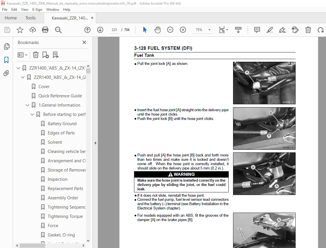
Fuel Tank Installation 224
Fuel Tank and Cap Inspection 226
Fuel Tank Cleaning 226
The Evaporative Emission Control System routes fuel vapors from 227
Parts Removal/Installation 227
Hose Inspection 227
Separator Inspection 227
Separator Operation Test 228
Canister Inspection 228
4 Cooling System 230
Coolant Deterioration Inspection 236
Coolant Level Inspection 236
Coolant Draining 236
Coolant Filling 236
Pressure Testing 236
Cooling System Flushing 237
Coolant Reserve Tank Removal/Installation 237
Water Pump Removal 238
Water Pump Installation 238
Torque – 239
Water Pump Impeller Inspection 239
Radiator and Radiator Fan Removal 240
Radiator and Radiator Fan Installation 241
Radiator Inspection 241
Radiator Cap Inspection 242
Radiator Filler Neck Inspection 242
Thermostat Removal 243
Thermostat Installation 243
Torque – 243
Thermostat Inspection 243
Hose Installation 245
Torque – 245
Hose Inspection 245
CAUTION 246
Water Temperature Sensor Removal 246
Water Temperature Sensor Inspection 246
5 Engine Top End 248
Compression Gauge, 20 kgf/cm : 256
Air Suction Valve Removal 258
Air Suction Valve Installation 258
Torque – 258
Air Suction Valve Inspection 259
Air Switching Valve Removal 259
Air Switching Valve Installation 259
Air Switching Valve Operation Test 259
Air Switching Valve Unit Test 259
Clean Air System Hose Inspection 259
Cylinder Head Cover Removal 260
Cylinder Head Cover Installation 260
Sealant – 260
Torque – 261
Camshaft Chain Tensioner Removal 262
Camshaft Chain Tensioner Installation 262
Torque – 262
Camshaft Removal 264
Camshaft Installation 264
Torque – 264
Torque – 267
Camshaft, Camshaft Cap Wear 267
Torque – 267
Camshaft Runout 268
Cam Wear 268
Camshaft Chain Removal 268
Camshaft Chain Installation 269
Torque – 269
Cylinder Compression Measurement 270
Owner’s Tool – 270
Special Tools – 270
Torque – 270
Cylinder Head Removal 271
Cylinder Head Installation 271
Torque – 272
Torque – 272
Torque – 272
Torque – 272
Cylinder Head Warp 272
Valve Clearance Inspection 273
Valve Removal 273
Special Tools – 273
Valve Installation 273
Valve Guide Removal 273
Special Tool – 273
Valve Guide Installation 274
Special Tools – 274
Special Tool – 274
Valve-to-Guide Clearance Measurement (Wobble Method) 275
Valve Seat Inspection 276
Valve Seat Repair 276
Special Tools – 276
Throttle Body Holder Installation 281
Torque – 281
WARNING 282
Muffler Body Removal/Installation 282
Torque – 283
Exhaust Pipe Removal 283
Exhaust Pipe Installation 283
Torque – 283
6 Clutch 284
Inside Circlip Pliers: 288
Clutch Lever Adjustment 289
Clutch Master Cylinder Removal 289
Clutch Master Cylinder Installation 289
Torque – 290
Torque – 290
Clutch Master Cylinder Disassembly 290
Clutch Master Cylinder Assembly 290
Clutch Master Cylinder Inspection 290
Special Tool – 290
Clutch Slave Cylinder Removal 291
Clutch Slave Cylinder Installation 292
Torque – 292
Clutch Slave Cylinder Disassembly 292
Clutch Slave Cylinder Assembly 292
Clutch Fluid Level Inspection 293
Clutch Fluid Change 293
Bleeding the Clutch Line 293
Torque – 294
Torque – 294
Clutch Hose Removal/Installation 294
Clutch Hose and Connection Inspection 294
Clutch Cover Removal 295
Clutch Cover Installation 295
Sealant – 295
Torque – 295
Clutch Removal 296
Special Tool – 296
Special Tool – 296
Clutch Installation 297
Special Tool – 297
Special Tool – 297
Torque – 297
Torque – 298
Clutch Plate Assembly Inspection 299
Torque – 299
Clutch Plate Assembly Adjustment 299
Torque – 299
Clutch Plate, Wear, Damage Inspection 300
Clutch Plate Warp Inspection 300
Clutch Spring Free Length Measurement 300
7 Engine Lubrication System 302
Oil Pressure Gauge, 10 kgf/cm : 308
WARNING 309
Oil Level Inspection 309
Engine Oil Change 309
Oil Filter Replacement 309
Oil Pan Removal 310
Oil Pan Installation 310
Torque – 310
Torque – 311
Oil Pressure Relief Valve Removal 312
Oil Pressure Relief Valve Installation 312
Oil Pressure Relief Valve Inspection 312
Oil Pump Removal 313
Oil Pump Installation 313
Torque – 314
Oil Cooler Removal 315
Oil Cooler Installation 315
Torque – 315
Torque – 315
Oil Pressure Measurement 316
Special Tools – 316
Torque – 316
Oil Pressure Switch Removal 317
Oil Pressure Switch Installation 317
Sealant – 317
Torque – 317
Torque – 317
8 Engine Removal/Installation 318
Engine Removal 321
Engine Installation 323
Torque – 326
Torque – 327
Torque – 327
9 Crankshaft/Transmission 330
Bearing Puller: 338
Crankcase Splitting 339
Crankcase Assembly 340
Torque – 340
Sealant – 341
Torque – 342
Torque – 342
Torque – 343
Crankshaft Removal 344
Crankshaft Installation 344
Connecting Rod Removal 345
Connecting Rod Installation 345
Crankshaft/Connecting Rod Cleaning 348
Connecting Rod Bend 348
Connecting Rod Twist 349
Connecting Rod Big End Side Clearance 349
Connecting Rod Big End Bearing Insert/Crankpin Wear 349
Crankshaft Side Clearance 351
Crankshaft Runout 352
Crankshaft Main Bearing Insert/Journal Wear 352
Piston Removal 355
Special Tool – 355
Piston Installation 356
Special Tools – 357
Cylinder Wear (Upper Crankcase) 357
Piston Wear 357
Piston Ring, Piston Ring Groove Wear 357
Piston Ring Groove Width 358
Piston Ring Thickness 358
Piston Ring End Gap 358
Front Balancer Removal 359
Front Balancer Installation 359
Torque – 360
Torque – 360
Rear Balancer Removal 360
Rear Balancer Installation 361
Torque – 362
Torque – 362
Balancer Adjustment 363
Torque – 363
Balancer Damper Inspection 363
Starter Motor Clutch Removal 364
Starter Motor Clutch Installation 364
Torque – 364
Torque – 364
Starter Motor Clutch Disassembly 364
Starter Motor Clutch Assembly 365
Starter Clutch Inspection 365
Torque Limiter Removal 365
Torque Limiter Installation 366
Torque – 366
Shift Pedal Removal 367
Shift Pedal Installation 367
External Shift Mechanism Removal 367
External Shift Mechanism Installation 368
Torque – 368
External Shift Mechanism Inspection 368
Torque – 368
Transmission Shaft Removal 368
Transmission Shaft Installation 369
Torque – 369
Transmission Shaft Disassembly 369
Special Tools – 370
Transmission Shaft Assembly 370
Shift Drum and Fork Removal 373
Shift Drum and Fork Installation 373
Torque – 373
Shift Drum Disassembly 373
Shift Drum Assembly 373
Torque – 373
Shift Fork Bending 374
Shift Fork/Gear Groove Wear 374
Shift Fork Guide Pin/Drum Groove Wear 374
Gear Dog and Gear Dog Hole Damage 374
10 Wheels/Tires 376
Bearing Driver Set: 380
Front Wheel Removal 381
Special Tools – 381
Front Wheel Installation 381
Torque – 382
Torque – 382
Rear Wheel Removal 382
Rear Wheel Installation 383
Torque – 383
Wheel Inspection 385
Special Tools – 385
Axle Inspection 385
Balance Inspection 386
Balance Adjustment 386
Balance Weight Removal 386
Balance Weight Installation 387
Air Pressure Inspection/Adjustment 389
Tire Inspection 389
Tire Removal 389
Tire Installation 389
Tire Repair 391
Hub Bearing Removal 392
Special Tools – 392
Hub Bearing Installation 392
Special Tool – 392
Special Tool – 392
Hub Bearing Inspection 392
Hub Bearing Lubrication 393
11 Final Drive 394
Inside Circlip Pliers: 398
Drive Chain Slack Inspection 399
Drive Chain Slack Adjustment 399
Wheel Alignment Inspection/Adjustment 399
Drive Chain Wear Inspection 399
Drive Chain Lubrication 399
Drive Chain Removal 399
Drive Chain Installation 399
Engine Sprocket Removal 400
Engine Sprocket Installation 400
Torque – 400
Torque – 400
Torque – 401
Rear Sprocket Removal 401
Rear Sprocket Installation 401
Torque – 401
Coupling Installation 401
Coupling Bearing Removal 402
Special Tool – 402
Special Tool – 402
Coupling Bearing Installation 402
Special Tool – 402
Special Tool – 402
Special Tool – 402
Coupling Bearing Inspection 403
Coupling Bearing Lubrication 403
Coupling Damper Inspection 403
Sprocket Wear Inspection 403
Rear Sprocket Warp Inspection 404
12 Brakes 406
Dummy Page 408
ZX1400A Models 409
ZX1400B Models 413
Inside Circlip Pliers: 418
Brake Lever Position Adjustment 419
Brake Pedal Position Inspection 419
Brake Pedal Position Adjustment 419
Torque – 419
Brake Pedal Removal 419
Brake Pedal Installation 420
Torque – 420
Torque – 420
Torque – 420
Front Caliper Removal 421
Rear Caliper Removal 421
Caliper Installation 422
Torque – 422
Front Caliper Disassembly 422
Front Caliper Assembly 422
Rear Caliper Disassembly 422
Rear Caliper Assembly 422
Caliper Fluid Seal Damage 423
Caliper Dust Seal Damage 423
Caliper Piston and Cylinder Damage 424
Front Brake Pad Removal 425
Front Brake Pad Installation 425
Torque – 425
Rear Brake Pad Removal 426
Rear Brake Pad Installation 426
Torque – 426
Brake Pad Wear Inspection 426
Front Master Cylinder Removal 427
Front Master Cylinder Installation 427
Torque – 427
Torque – 427
Rear Master Cylinder Removal 427
Rear Master Cylinder Installation 428
Torque – 428
Front Master Cylinder Disassembly 428
Rear Master Cylinder Disassembly 428
Master Cylinder Assembly 428
Master Cylinder Inspection (Visual Inspection) 428
Brake Disc Removal 430
Brake Disc Installation 430
Torque – 430
Brake Disc Wear 430
Brake Disc Warp 430
Special Tools – 430
Brake Fluid Level Inspection 431
Brake Fluid Change 431
Brake Line Bleeding 431
Torque – 432
Torque – 433
Torque – 433
Brake Hose and Pipe Removal/Installation 435
Brake Hose and Pipe Inspection 435
Parts Location 436
ABS System Wiring Diagram 437
Terminal Names 438
ABS Servicing Precautions 439
ABS Troubleshooting Outline 441
Special Tool – 441
Special Tool – 442
ABS Diagnosis Flow Chart 443
Inquiries to Rider 444
Pre-Diagnosis Inspection 1 445
Pre-Diagnosis Inspection 2 446
Self-diagnosis Outline 446
Self-diagnosis Procedures 446
Service Code Clearing Procedures 447
Self-diagnosis Flow Chart 449
How to Read Service Codes 450
How to Erase Service Codes 450
ABS Indicator Light (LED) Inspection 452
ABS Indicator Light (LED) is Unlit (When the Ignition Switch tur 452
Special Tool – 452
ABS Indicator Light (LED) Lights (When the Motorcycle is Running 453
Special Tool – 453
Solenoid Valve Inspection (Service Code 13,14,17,18) 453
ABS Solenoid Valve Relay Inspection (Service Code 19) 453
Special Tool – 454
Front, Rear Wheel Rotation Difference Abnormal (Service Code 25) 455
ABS Pump Motor Relay Inspection (Service Code 35) 455
Special Tool – 456
Front Wheel Rotation Sensor Signal Abnormal (Service Code 42) 456
Front Wheel Rotation Sensor Wiring Inspection (Service Code 43) 457
Rear Wheel Rotation Sensor Signal Abnormal (Service Code 44) 458
Rear Wheel Rotation Sensor Wiring Inspection (Service Code 45) 459
Power Supply Voltage Abnormal (Under-Voltage) (Service Code 52) 459
Special Tool – 460
Power Supply Voltage Abnormal (Over-Voltage) (Service Code 53) 460
Special Tool – 461
ECU Inspection (Service Code 55) 461
ABS Hydraulic Unit Removal 461
ABS Hydraulic Unit Installation 463
Torque – 463
ABS Hydraulic Unit Inspection 464
Front Wheel Rotation Sensor Removal 464
Front Wheel Rotation Sensor Installation 464
Rear Wheel Rotation Sensor Removal 465
Rear Wheel Rotation Sensor Installation 465
Wheel Rotation Sensor Inspection 466
Wheel Rotation Sensor Air Gap Inspection 466
Wheel Rotation Sensor Rotor Inspection 467
ABS Solenoid Valve Relay Fuse (20 A) Removal 467
ABS Motor Relay Fuse (30 A) Removal 467
ABS ECU Fuse (10 A) Removal 467
Fuse Installation 468
Fuse Inspection 468
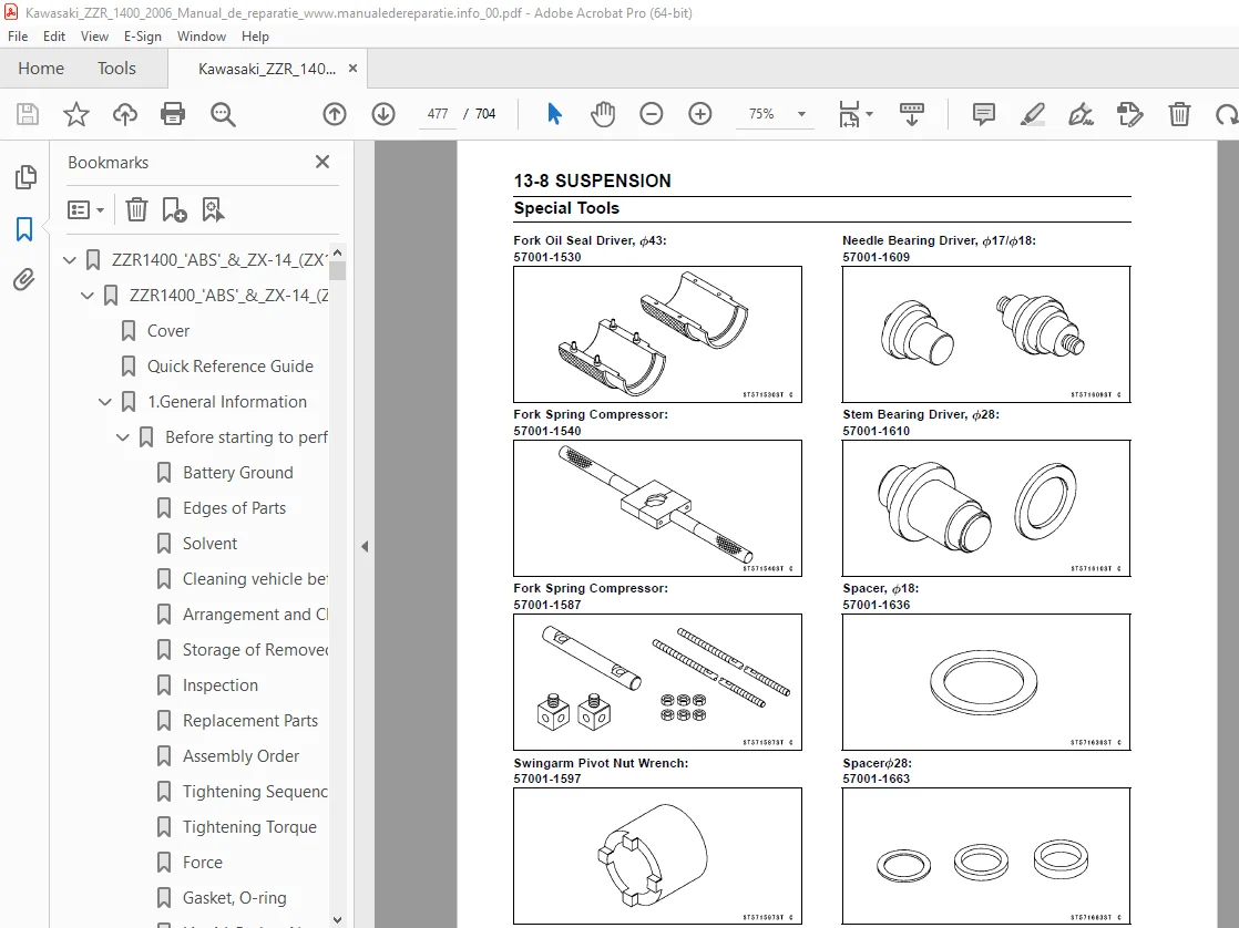
13 Suspension 470
Inside Circlip Pliers: 476
Rebound Damping Force Adjustment 478
Compression Damping Force Adjustment 478
Spring Preload Adjustment 479
Front Fork Removal (Each Fork Leg) 479
Front Fork Installation 480
Torque – 480
Torque – 480
Front Fork Oil Change 480
Special Tools – 480
Special Tool – 482
Special Tool – 483
Special Tool – 483
Special Tool – 483
Special Tools – 484
Torque – 484
Front Fork Disassembly 485
Special Tool – 485
Front Fork Assembly 485
Special Tool – 485
Torque – 485
Special Tool – 486
Inner Tube Inspection 486
Dust Seal Inspection 487
Spring Tension 487
Rebound Damping Force Adjustment 488
Compression Damping Force Adjustment 488
Spring Preload Adjustment 488
Special Tool – 488
Special Tool – 489
Rear Shock Absorber Removal 489
Special Tools – 489
Rear Shock Absorber Installation 490
Torque – 490
Rear Shock Absorber Inspection 490
Rear Shock Absorber Scrapping 491
Swingarm Removal 492
Special Tool – 492
Swingarm Installation 493
Torque – 493
Special Tool – 493
Torque – 493
Torque – 493
Swingarm Bearing Removal 494
Special Tool – 494
Special Tool – 494
Swingarm Bearing Installation 494
Special Tools – 494
Swingarm Bearing, Sleeve Inspection 495
Chain Guide Inspection 496
Tie-Rod Removal 497
Special Tools – 497
Tie-Rod Installation 497
Torque – 497
Rocker Arm Removal 497
Special Tools – 497
Rocker Arm Installation 498
Torque – 498
Tie-Rod and Rocker Arm Bearing Removal 498
Special Tools – 498
Tie-Rod and Rocker Arm Bearing Installation 498
Special Tools – 499
Rocker Arm/Tie-Rod Bearing, Sleeve Inspection 500
Rocker Arm/Tie-Rod Bearing Lubrication 500
14 Steering 502
Head Pipe Outer Race Press Shaft: 505
Steering Inspection 506
Steering Adjustment 506
Stem, Stem Bearing Removal 507
Special Tool – 507
Special Tool – 507
Stem, Stem Bearing Installation 508
Special Tools – 508
Special Tools – 508
Special Tool – 509
Torque – 509
Torque – 510
Steering Stem Bearing Lubrication 510
Steering Stem Warp 510
Stem Cap Deterioration, Damage 510
Handlebar Removal 511
Handlebar Installation 511
Torque – 511
Torque – 512
Torque – 512
15 Frame 514
Seat Removal 523
Seat Installation 523
Lower Fairing Removal 524
Lower Fairing Installation 524
Fairing Cover Removal 524
Middle Fairing Removal 524
Middle Fairing Installation 525
Windshield Removal 525
Windshield Installation 526
Torque – 526
Upper Fairing Removal 526
Upper Fairing Disassembly 526
Upper Fairing Assembly 526
Upper Fairing Installation 527
Inner Cover Removal 527
Inner Cover Installation 527
Upper Inner Fairing Removal 527
Upper Inner Fairing Installation 528
Upper Fairing Bracket Removal 528
Upper Fairing Bracket Installation 528
Inner Fairing Removal 528
Inner Fairing Installation 528
Rear Fairing Removal 528
Rear Fairing Installation 528
Seat Cover Removal 529
Seat Cover Installation 529
Torque – 530
Front Fender Removal 531
Front Fender Installation 531
Flap and Rear Fender Removal 531
Flap and Rear Fender Installation 532
Torque – 532
Rear Frame Removal 533
Rear Frame Installation 533
Torque – 533
Frame Inspection 533
Center Stand Removal (Equipped Models) 534
Center Stand Installation (Equipped Models) 534
Torque – 534
Sidestand Removal 534
Sidestand Installation 534
Torque – 534
Torque – 534
16 Electrical System 536
Hand Tester: 554
There are a number of important precautions that are musts when 556
Wiring Inspection 557
Special Tool – 557
Battery Removal 558
Battery Installation 559
Battery Activation 559
Precautions 562
1) 562
2) 562
3) 562
4) 562
Interchange 562
Charging Condition Inspection 562
Refreshing Charge 563
Alternator Cover Removal 564
Alternator Cover Installation 564
Sealant – 564
Torque – 564
Stator Coil Removal 564
Stator Coil Installation 565
Torque – 565
Sealant – 565
Torque – 565
Alternator Rotor Removal 565
Special Tools – 565
Special Tool – 565
Alternator Rotor Installation 565
Special Tools – 566
Torque – 566
Alternator Inspection 566
Special Tool – 567
Regulator/Rectifier Inspection 568
Special Tool – 568
Torque – 568
Charging Voltage Inspection 569
Special Tool – 569
Charging System Circuit 570
Crankshaft Sensor Removal 572
Crankshaft Sensor Installation 573
Torque – 573
Sealant – 573
Torque – 573
Crankshaft Sensor Inspection 573
Special Tool – 573
Crankshaft Sensor Peak Voltage Inspection 573
Special Tools – 574
Stick Coil (Ignition Coil together with Spark Plug Cap) Removal 574
Stick Coil (Ignition Coil together with Spark Plug Cap) Installa 574
Stick Coil (Ignition Coil together with Spark Plug Cap) Inspecti 575
Stick Coil Primary Peak Voltage 575
Special Tools – 575
Spark Plug Removal 576
Spark Plug Installation 576
Spark Plug Condition Inspection 576
Camshaft Position Sensor Removal 577
Camshaft Position Sensor Installation 577
Torque – 577
Camshaft Position Sensor Inspection 577
Special Tool – 577
Camshaft Position Sensor Peak Voltage Inspection 578
Special Tools – 578
Interlock Operation Inspection 578
IC Igniter Inspection 579
Ignition System Circuit 580
Starter Motor Removal 581
Starter Motor Installation 581
Torque – 581
Torque – 581
Starter Motor Disassembly 582
Starter Motor Assembly 582
Torque – 582
Torque – 583
Brush Inspection 583
Commutator Cleaning and Inspection 584
Armature Inspection 584
Special Tool – 584
Brush Lead Inspection 584
Special Tool – 584
Right-hand End Cover Assembly Inspection 585
Special Tool – 585
Starter Relay Inspection 585
Special Tool – 585
Torque – 585
Electric Starter Circuit 586
This motorcycle adopt the daylight system and have a headlight r 587
Headlight Beam Horizontal Vertical Adjustment 587
Headlight Beam Vertical Adjustment 587
Headlight Bulb Replacement 587
City Light Bulb Replacement 588
Headlight Removal/Installation 588
Torque – 588
Headlight Relay Inspection 589
Special Tool – 589
Tail/Brake Light (LED) Removal 589
Tail/Brake Light (LED) Installation 590
Torque – 590
License Plate Light Bulb Replacement 590
Torque – 590
Headlight/Tail Light Circuit 591
Turn Signal Light Bulb Replacement 591
Turn Signal Relay Inspection 593
Turn Signal Light Circuit 594
Air Switching Valve Operation Test 595
Air Switching Valve Unit Test 595
Special Tool – 595
Fan Motor Inspection 596
Radiator Fan Circuit 596
Meter Unit Removal 597
Meter Unit Installation 597
Meter Unit Disassembly 598
Meter Unit Inspection 598
Special Tool – 599
Special Tool – 609
Special Tool – 610
Meter Unit Circuit 614
This motorcycle is equipped with an immobilizer system to protec 615
Operational Cautions 615
Key Registration 615
Special Tool – 615
Spare User Key Registration Flow Chart 620
Special Tool – 621
All Keys Initial Registration Flow Chart 630
Immobilizer System Parts Replacement 631
ECU (Electric Control Unit) Replacement (for Immobilizer Models) 632
Immobilizer System Inspection 633
Immobilizer System Circuit 634
Brake Light Timing Inspection 635
Brake Light Timing Adjustment 635
Switch Inspection 635
Special Tool – 635
Rear Brake Light Switch Connections 635
Sidestand Switch Connections 635
Oil Pressure Switch Connections * 635
Water Temperature Sensor Inspection 636
Speed Sensor Removal 636
Speed Sensor Installation 636
Torque – 636
Speed Sensor Inspection 637
Special Tool – 637
Fuel Level Sensor Inspection 637
Special Tools – 637
Torque – 638
Fuel Reserve Switch Inspection 638
Special Tool – 638
Gear Position Switch Removal 639
Gear Position Switch Installation 640
Torque – 640
Gear Position Switch Inspection 640
Special Tool – 640
The relay box [A] has relays and diodes The relays and diodes c 641
Relay Box Removal 641
Relay Circuit Inspection 641
Diode Circuit Inspection 642
Relay Box Internal Circuit 643
30 A Main Fuse Removal 644
Fuse Box Fuse Removal 644
15 A ECU Fuse Removal 645
Fuse Installation 645
Fuse Inspection 646
17 Appendix 648
ZX1400B Models 673
ZX1400B Models 683
ZX1400B Models 685
ZX1400B Models 687
ZX1400B Models 689
ZX1400B Models 691
ZX1400B Models 693
ZX1400B Models 695
California Model 697
NOTE 699
Engine Doesn’t Start, Starting Difficulty: 699
Starter motor not rotating: 699
Starter motor rotating but engine doesn’t turn over: 699
Engine won’t turn over: 699
No fuel flow: 699
No spark; spark weak: 699
Fuel/air mixture incorrect: 699
Compression Low: 699
Poor Running at Low Speed: 699
Spark weak: 699
Fuel/air mixture incorrect: 699
Compression low: 700
Run-on (dieseling): 700
Other: 700
Poor Running or No Power at High Speed: 700
Firing incorrect: 700
Fuel/air mixture incorrect: 700
Compression low: 700
Knocking: 700
Miscellaneous: 700
Overheating: 700
Firing incorrect: 700
Muffler overheating: 700
Fuel/air mixture incorrect: 700
Compression high: 701
Engine load faulty: 701
Lubrication inadequate: 701
Oil cooler incorrect: 701
Gauge incorrect: 701
Coolant incorrect: 701
Cooling system component incorrect: 701
Over Cooling: 701
Gauge incorrect: 701
Cooling system component incorrect: 701
Clutch Operation Faulty: 701
Clutch slipping: 701
Clutch not disengaging properly: 701
Gear Shifting Faulty: 701
Doesn’t go into gear; shift pedal doesn’t return: 701
Jumps out of gear: 701
Overshifts: 701
Abnormal Engine Noise: 701
Knocking: 701
Piston slap: 701
Valve noise: 701
Other noise: 701
Abnormal Drive Train Noise: 702
Clutch noise: 702
Transmission noise: 702
Drive line noise: 702
Abnormal Frame Noise: 702
Front fork noise: 702
Rear shock absorber noise: 702
Disc brake noise: 702
Other noise: 702
Oil Pressure Warning Light Goes On: 702
Exhaust Smokes Excessively: 702
White smoke: 702
Black smoke: 702
Brown smoke: 702
Handling and/or Stability Unsatisfactory: 702
Handlebar hard to turn: 702
Handlebar shakes or excessively vibrates: 702
Handlebar pulls to one side: 702
Shock absorption unsatisfactory: 702
Brake Doesn’t Hold: 703
Battery Trouble: 703
Battery discharged: 703
Battery overcharged: 703
DESCRIPTION:
Kawasaki ZZR 1400 ZZR1400 ABS Ninja ZX-14 Motorcycle Service Manual – PDF DOWNLOAD
FOREWORD:
- This manual is designed primarily for use by trained mechanics in a properly equipped shop. However, it contains enough detail and basic information to make it useful to the owner who desires to perform his own basic maintenance andrepair work. A basic knowledge of mechanics, the proper use of tools, and workshop procedures must be understood in order to carry outmaintenance and repair satisfactorily. Whenever the owner has insufficient experience or doubts his ability to do the work, all adjustments, maintenance, and repair should be carried out only by qualified mechanics.
- In order to perform the work efficiently and to avoid costly mistakes, read the text, thoroughly familiarize yourself with the procedures before starting work, and then do the work carefullyin a clean area. Whenever special tools or equipment are specified, do not use makeshift tools or equipment. Precision measurements can only be made if the proper instruments are used, and the use of substitute tools may adversely affect safe operation.
- For the duration of the warranty period, we recommend that all repairs and scheduled maintenance be performed in accordance with this servicemanual. Any owner maintenance or repair procedure not performed in accordance with this manual may void the warranty.
To get the longest life out of your vehicle:
S.V 18/03/2025