
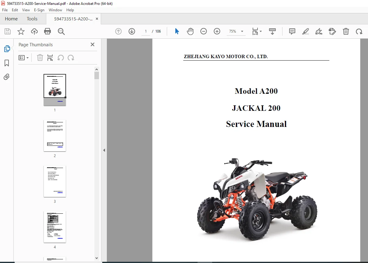
Kayo A200 Jackal 200 ATV Service Manual 200cc Repair Workshop Guide PDF
Original price was: $95.00.$25.95Current price is: $25.95.
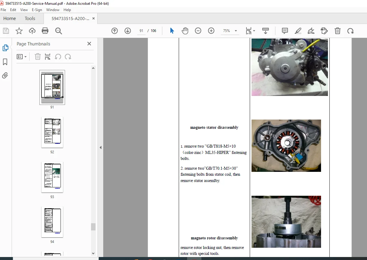
Complete Kayo A200 Jackal 200 ATV service manual from Zhejiang Kayo Motor Co. Comprehensive workshop manual covering 200cc utility ATV maintenance, adjustments, disassembly, installation, and specifications. Includes detailed engine overhaul procedures, transmission service, electrical schematics, plastics/body parts, regular maintenance schedules, and torque specifications. Essential repair guide for mechanics servicing Kayo 200cc four-stroke single-cylinder ATVs with manual transmission.
Description
Kayo A200 Jackal 200 ATV Service Manual 200cc Repair Workshop Guide PDF DOWNLOAD
DESCRIPTION
Complete Kayo A200 Jackal 200 ATV Service & Repair Manual
This is the official service manual from Zhejiang Kayo Motor Co., Ltd. for the Kayo A200 (Jackal 200) 200cc utility all-terrain vehicle. This comprehensive 106-page professional workshop manual provides complete technical documentation for maintenance, repair, disassembly, installation, and inspection of the Kayo A200 ATV, published March 2020.
📋 File Details
- Manual Name: Kayo A200 / Jackal 200 Service Manual
- Model: A200 (Jackal 200)
- Type: 200cc Utility ATV
- Manufacturer: Zhejiang Kayo Motor Co., Ltd.
- Publication Date: March 2020
- Pages: 106 pages
- File Quality: High-resolution PDF (A4 size)
- File Size: 5.6 MB
- Language: English
🏍️ Kayo A200 Jackal 200 Specifications
Vehicle Dimensions:
- Overall (L×W×H): 1700mm × 1050mm × 1080mm (66.9″ × 41.3″ × 42.5″)
- Wheelbase: 1100mm (43.3″)
- Handlebar width: 860mm (33.9″)
- Handlebar height: 1080mm (42.5″)
- Seat height: 830mm (32.7″)
- Ground clearance: 120mm (4.7″)
- Turning radius: 2500mm (98.4″)
- Turning angle: 38° ± 2°
Weight:
- Net weight: 155 kg (342 lbs)
- Curb weight (with battery + fuel): 164.8 kg (363 lbs)
Performance:
- Maximum speed: 70 km/h (43.5 mph) – speed limited
Engine Specifications:
- Type: Single cylinder, 4-stroke, air-cooled
- Valve train: SOHC (Single Overhead Cam), chain-driven
- Bore × Stroke: 65mm × 59mm
- Displacement: 196cc
- Compression ratio: 9.2:1
- Cooling: Natural air cooling
- Lubrication: Combination splash and pressure feed
- Oil pump: Rotor type with mesh oil cooler
- Oil capacity: Uses complete filtrate, sponge filter
- Recommended oil: 10W/40-SJ grade or SAE-15W-40 four-stroke
- Oil pressure:
- 1500 rpm @ 90°C: 200-400 kPa (general 240 kPa)
- 6000 rpm @ 90°C: 600-700 kPa (general 600 kPa)
Fuel System:
- Carburetor: SG30·VM26 with choke switch
- Fuel pump: Rotor type
- Fuel tank capacity: 6 liters (1.6 gallons)
- Air filter: Sponge element type
- Starting: Electric start
Transmission:
- Clutch: Manual wet clutch
- Gearbox: 5-speed + Reverse, foot-shift
- Gear pattern: R-N-1-2-3-4-5
- Shift direction: Rear for upshift, front for downshift
Wheels & Tires:
- Front tire pressure: 4.0 PSI
- Rear tire pressure: 4.0 PSI
- Minimum tread depth: 3.0mm
- Rim runout limits:
- Vertical: 2.0mm max
- Horizontal: 1.8mm max
Brake System:
- Front brake: Dual disc hydraulic
- Disc thickness: 3.5mm (standard), 3.0mm (limit)
- Brake lever stroke: 5-10mm
- Braking force: 400 N·m
- Rear brake: Single disc hydraulic
- Disc thickness: 3.5mm (standard)
- Brake lever stroke: 10-20mm
Oil Pump Specifications:
- Inner/outer rotor radial clearance: 0.07-0.15mm (limit 0.2mm)
- Outer rotor to pump body clearance: 0.03-0.10mm (limit 0.12mm)
- Rotor axial clearance: 0.023-0.055mm (limit 0.12mm)
📚 Comprehensive Manual Contents
CHAPTER 1: MAINTENANCE INFORMATION
1.1 Safety Precautions:
- Safety first guidelines – Proper work attire and protective equipment
- Working environment safety:
- Engine ventilation requirements
- Burn prevention protocols
- Battery safety (sulfuric acid handling)
- Gasoline handling and fire prevention
- Rotating parts hazards
- Disassembly and installation precautions:
- Parts sorting and organization
- Pre-disassembly cleaning procedures
- One-time use parts identification (gaskets, O-rings, piston pins, piston rings, cotter pins)
- Snap ring handling
- Compressed air cleaning procedures
- Lubrication requirements
- Bolt/nut torque tightening sequences (diagonal pattern, large to small, inside to outside)
- Rubber parts inspection and chemical compatibility
- Special tools requirements
- Ball bearing inspection procedures
- Bearing installation orientation
- Snap ring installation procedures
- Brake fluid and coolant handling
- Oil seal installation guidelines
- Rubber hose installation procedures
- Gasket surface preparation
- Cable handling and routing
- Protective cap/cover installation
1.2 VIN Number Identification:
- VIN number location with diagram
- Name plate location
- Engine number location
1.3 Main Parameters List:
- Complete vehicle specifications table
- Engine specifications
- Transmission specifications
- Chassis specifications
- Brake system specifications
- Electrical system specifications
1.4 Maintenance Parameters List:
- Recommended fluids and lubricants
- Oil pump rotor clearances and limits
- Air intake system specifications
- Oil cooling device specifications
- Wheel and tire specifications
- Brake system measurements
1.5 Torque Tightening Specifications:
- Comprehensive torque values for all fasteners
- Critical bolts and nuts torque settings
- Sequential tightening procedures
1.6 Lubricants and Sealants:
- Recommended lubricant types and brands
- Application locations
- Sealant specifications
1.7 Cable, Hose and Wiring Diagram:
- Cable routing diagrams
- Hose connection specifications
- Wiring layout overview
Conversion Tables:
- Pressure conversion (kgf/cm², kPa, PSI, mmHg)
- Torque conversion (kgf·m, N·m)
- Volume conversion (mL, cm³, cc, L)
- Force conversion (kgf, N)
- Length conversion (inches, mm)
Warning System:
- Danger – High alert warnings
- Warning – Moderate danger warnings
- Attention – Minor danger warnings
CHAPTER 2: PLASTICS AND BODY PARTS
Complete body component coverage:
- Front fender assembly removal/installation
- Rear fender assembly procedures
- Side panels and covers
- Seat removal and installation
- Body panel fastener locations
- Luggage rack mounting
- Headlight/taillight housing
- Front grill assembly
- Mud guards
- Number plate holder
- Handlebar covers
- Fuel tank cover
- Skid plate mounting
- Exploded view diagrams with part numbers
- Fastener torque specifications
- Alignment procedures
CHAPTER 3: REGULAR MAINTENANCE AND ADJUSTMENT
Periodic Maintenance Schedules:
- Daily checks before operation
- Weekly maintenance procedures
- Monthly service requirements
- Seasonal maintenance tasks
Specific Maintenance Procedures:
- Engine oil and filter change:
- Drain procedures
- Filter replacement
- Oil capacity specifications
- Oil grade recommendations
- Air filter service:
- Sponge element cleaning
- Inspection criteria
- Replacement intervals
- Spark plug service:
- Removal and inspection
- Gap specifications
- Torque specifications
- Valve clearance adjustment:
- Measurement procedures
- Adjustment specifications
- Timing considerations
- Carburetor adjustment:
- Idle speed setting
- Air/fuel mixture adjustment
- Synchronization procedures
- Chain maintenance:
- Tension adjustment
- Lubrication procedures
- Wear inspection
- Brake system maintenance:
- Brake fluid level checks
- Pad inspection and replacement
- Disc inspection and measurement
- Brake lever adjustment
- Hydraulic system bleeding
- Tire and wheel service:
- Pressure checks
- Tread depth inspection
- Wheel bearing maintenance
- Rim runout measurement
- Battery maintenance:
- Charging procedures
- Terminal cleaning
- Electrolyte level checks
- Cooling system checks:
- Air flow verification
- Fin cleaning procedures
- Fuel system maintenance:
- Tank cleaning
- Fuel line inspection
- Carburetor cleaning
- Electrical system checks:
- Light operation
- Switch testing
- Wiring inspection
- Fuse checking
CHAPTER 4: OUTER PARTS OF ENGINE
External engine component service:
- Cylinder head cover removal/installation
- Carburetor service:
- Complete disassembly procedures
- Jet cleaning and inspection
- Float level adjustment
- Needle valve inspection
- Choke operation verification
- Exhaust system:
- Muffler removal/installation
- Exhaust pipe removal
- Gasket replacement
- Mounting bracket service
- Cooling fins cleaning
- Ignition system:
- Spark plug removal/installation
- Ignition coil testing
- CDI unit location
- Electric starter motor:
- Removal procedures
- Testing specifications
- Installation procedures
- Clutch cover removal/installation
- External oil lines and connections
- Engine mount inspection
- Crankcase breather system
- Oil pump access procedures
CHAPTER 5: ENGINE INTERNALS
Complete engine overhaul procedures:
5.1 Engine Removal from Frame:
- Step-by-step removal sequence
- Support and lifting procedures
- Connection identification and labeling
- Safety precautions
5.2 Engine Disassembly:
- Cylinder head removal:
- Bolt loosening sequence
- Head gasket inspection
- Warpage measurement procedures
- Valvetrain components:
- Camshaft removal
- Cam chain tensioner service
- Rocker arm inspection
- Valve guide inspection
- Valve seat inspection and measurement
- Valve spring testing
- Valve stem seal replacement
- Cylinder and piston:
- Cylinder removal procedures
- Piston removal
- Piston ring removal/installation
- Piston pin removal/installation
- Piston clearance measurement
- Cylinder bore measurement
- Ring gap measurement
- Ring groove clearance measurement
- Clutch assembly:
- Clutch cover removal
- Pressure plate removal
- Friction plate inspection
- Steel plate inspection
- Spring testing
- Hub inspection
- Transmission:
- Shift drum removal
- Shift forks inspection
- Gear inspection and measurement
- Bearing replacement
- Selector mechanism service
- Crankcase splitting:
- Bolt removal sequence
- Case separation procedures
- Crankshaft removal
- Main bearing inspection
- Oil seal replacement
- Crankshaft assembly:
- Connecting rod inspection
- Big end bearing clearance measurement
- Crankshaft runout measurement
- Small end bearing replacement
- Balance shaft service (if equipped)
- Oil pump:
- Rotor removal
- Clearance measurements
- Pressure relief valve inspection
- Screen cleaning
5.3 Component Inspection:
- Measurement specifications for all major components
- Wear limit specifications
- Replacement criteria
- Special tool requirements
5.4 Engine Assembly:
- Assembly sequence
- Torque specifications for all fasteners
- Gasket and seal installation
- Lubrication points during assembly
- Timing alignment procedures
- Cam chain installation
- Valve adjustment after assembly
5.5 Engine Installation:
- Engine mounting procedures
- Connection routing
- Fluid filling procedures
- Initial break-in procedures
APPENDIX: ELECTRICAL SCHEMATIC DIAGRAMS
Complete wiring diagrams:
- Main wiring harness layout
- Ignition system schematic
- Charging system diagram
- Starting system circuit
- Lighting circuits:
- Headlight circuit
- Taillight circuit
- Turn signal circuit (if equipped)
- Brake light circuit
- Switch locations and connections:
- Ignition switch
- Kill switch
- Light switch
- Brake light switches
- Electrical components:
- Battery connections
- Fuse box layout
- CDI unit connections
- Voltage regulator/rectifier
- Starter relay
- Starter motor wiring
- Color code legend
- Connector identification
- Ground points
- Troubleshooting guides
⚙️ Key Features Documented
Air-Cooled 200cc Engine:
- SOHC valve train with chain drive
- Single cylinder four-stroke design
- 9.2:1 compression ratio
- Rotor-type fuel pump
- Combination splash/pressure lubrication
- Complete overhaul procedures
Manual Transmission:
- 5-speed plus reverse
- Foot-shift operation
- Wet clutch design
- Complete service procedures
Hydraulic Disc Brakes:
- Dual front discs
- Single rear disc
- Complete bleeding procedures
- Adjustment specifications
Utility ATV Design:
- 200cc displacement for work/recreation
- Electric start system
- 6-liter fuel capacity
- Manual transmission control
- Rugged construction
🎯 Who Should Use This Manual?
- ATV mechanics servicing Kayo vehicles
- Powersports technicians working on Chinese ATVs
- Small engine repair shops maintaining utility ATVs
- Farm equipment mechanics servicing agricultural ATVs
- DIY enthusiasts performing their own maintenance
- ATV dealers providing service support
- Technical schools teaching ATV repair
- Fleet maintenance personnel managing ATV fleets
✅ Why This Manual is Essential
✔ Official Kayo documentation – Authentic manufacturer service guide
✔ Complete coverage – All systems documented in detail
✔ Engine overhaul procedures – Step-by-step internal engine work
✔ Torque specifications – All critical fastener values
✔ Electrical schematics – Complete wiring diagrams
✔ Maintenance schedules – Periodic service intervals
✔ Safety procedures – Proper handling and precautions
✔ Parts identification – Exploded views with part numbers
✔ Adjustment procedures – Valve, carburetor, chain, brake specs
✔ Troubleshooting guidance – Diagnostic procedures
✔ Conversion tables – Metric/imperial conversions
📥 Instant Digital Download
Receive your PDF manual immediately after purchase. Compatible with all devices – desktop, laptop, tablet, smartphone. Print sections for shop use or keep digital for quick reference during repairs.