Trusted Business
Verified & Licensed
Virus Free Files
100% Safe Downloads
Secure Payment
SSL Protected
Instant Delivery
Available Immediately
KCM 60Z7 Wheel Loader DEUTZ TCD36 Engine Shop Manual PDF
$29.95
KCM 60Z7 Wheel Loader(General Information Function & Structure) DEUTZ TCD36 Engine Shop Manual – PDF DOWNLOAD
SN 60D1-8001 and up
PN 93206-00370
Instant PDF Download
Available immediately
Save to Your Device
Download & keep forever
Antivirus Scanned
100% virus-free
Trusted Worldwide
175,000+ customers
Description
KCM 60Z7 Wheel Loader(General Information Function & Structure) DEUTZ TCD36 Engine Shop Manual – PDF DOWNLOAD
FILE DETAILS:
KCM 60Z7 Wheel Loader(General Information Function & Structure) DEUTZ TCD36 Engine Shop Manual – PDF DOWNLOAD
SN 60D1-8001 and up
PN 93206-00370
Language : English
Pages : 409
Downloadable : Yes
File Type : PDF
IMAGES PREVIEW OF THE MANUAL:
TABLE OF CONTENTS:
KCM 60Z7 Wheel Loader(General Information Function & Structure) DEUTZ TCD36 Engine Shop Manual – PDF DOWNLOAD
SN 60D1-8001 and up
PN 93206-00370
INTRODUCTION 4
Symbol and Abbreviation6
1 GENERAL8
Group 1 Specifications 8
Specifications10
Group 2 Component Layout12
Main Component (Overview) 12
Main Component (Travel System)13
Electrical System (Overview)14
Electrical System (Components Related with Relays)15
Electrical System (Components Related with Engine)15
Electrical System (Cab) 16
Engine21
Pump Device 22
Transmission/HST Motor23
Control Valve 24
Priority Valve25
Ride Control Valve (Option) 26
Secondary Steering Block (Option) 27
Secondary Steering Pump (Option)27
Pilot Shut-Off Solenoid Valve (Hydraulic Operated Type: Option) 28
Group 3 Component Specifications30
Engine30
Engine Accessories34
Hydraulic Component 36
Electrical Component41
2 SYSTEM44
Group 1 Controller46
Outline 46
CAN Circuit 47
Group 2 Control System50
Outline 50
Engine Control52
Accelerator Pedal Control 53
HST Pump Control55
HST Pump Control System Layout56
Forward/Reverse Lever Control 57
HST Brake 63
HST Motor Control 69
Driving Slow Speed Selection Control71
Traction Force Limit Control73
Traction Control75
Overrun Limit Control 77
Engine Protection Control 79
Overheat Prevention Control 81
Driving Slow Speed Switching Shock Reduction Control83
Transmission Control87
Driving Slow Speed Selection Control89
Other Controls93
Backup Light Lighting Control 95
Ride Control Function (Option)97
Parking Brake Operation Indicator Control 99
Secondary Steering Control (Option)101
Bucket Auto Leveler Control105
Lift Arm Float Control (Hydraulic Pilot Type) (Option) 109
Lift Arm Kickout Control (Hydraulic Pilot Type) (Option) 111
Group 3 ECM System 114
Outline114
Fuel Injection Control 115
EGR Control123
Neutral Engine Start Control 125
Engine Trouble Alarm Control 127
Engine Oil Pressure Alarm Control129
Overheat Alarm Control 130
Group 4 Hydraulic System 132
Outline132
Main Circuit 133
Secondary Steering Circuit (Option)143
Lift Arm, Bucket Circuit 145
HST Circuit153
Transmission Circuit 164
Clutch Circuit 164
Outline of Brake Circuit 168
Ride Control Circuit (Option)173
Pilot Circuit (Only Hydraulic Operated Type)(Option) 175
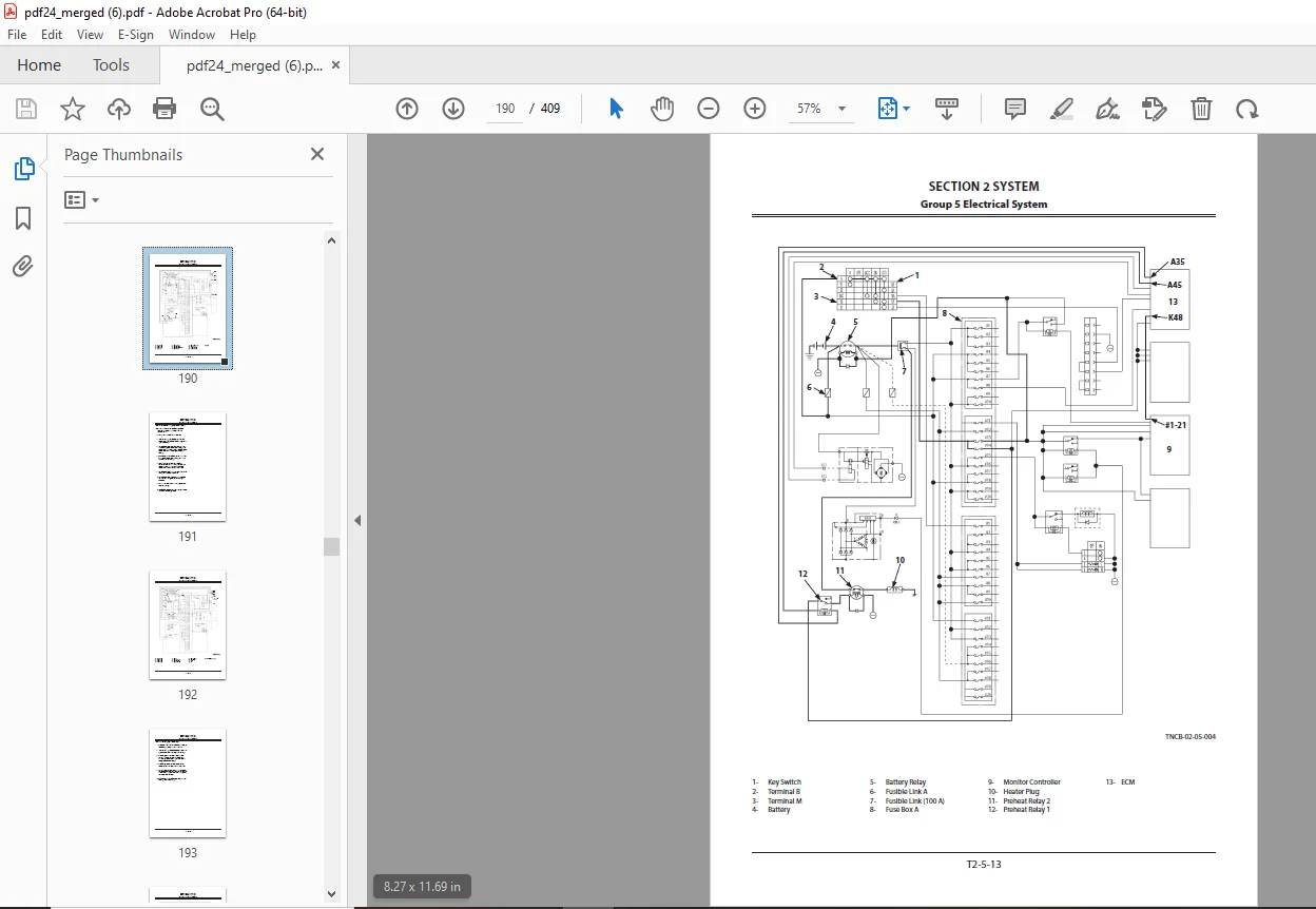
Group 5 Electrical System178
Outline178
Main Circuit 179
Accessory Circuit: 206
Wiper/Washer Circuit 207
Cab Light Circuit221
Light/Horn Circuit 224
3 COMPONENT OPERATION252
Group 1 Pump Device254
Outline254
HST Pump 255
Operational Principle256
Displacement Angle Control Cylinder257
In Neutral:258
Forward: 259
Reverse: 261
DA Valve 263
Forward/Reverse Control Solenoid Valve 264
Forward Travel 265
Reverse Travel 266
Cutoff Valve 268
Forward Operation: 269
Reverse Operation: 270
High-Pressure Relief Valve 271
Relief Operation 271
Make-Up Operation273
Low-Pressure Relief Valve275
HST Charging Pump276
Main Pump, Brake/Transmission Pump 277
Group 2 Control Valve278
Outline (Manually Operated Type) 278
Hydraulic Circuit281
Main Circuit 281
Main Relief Valve283
Overload Relief Valve (Bucket: Rod Side) 285
Outline (Hydraulic Operated Type) (Option) 290
Hydraulic Circuit293
Main Circuit 293
Pilot Operation Control Circuit295
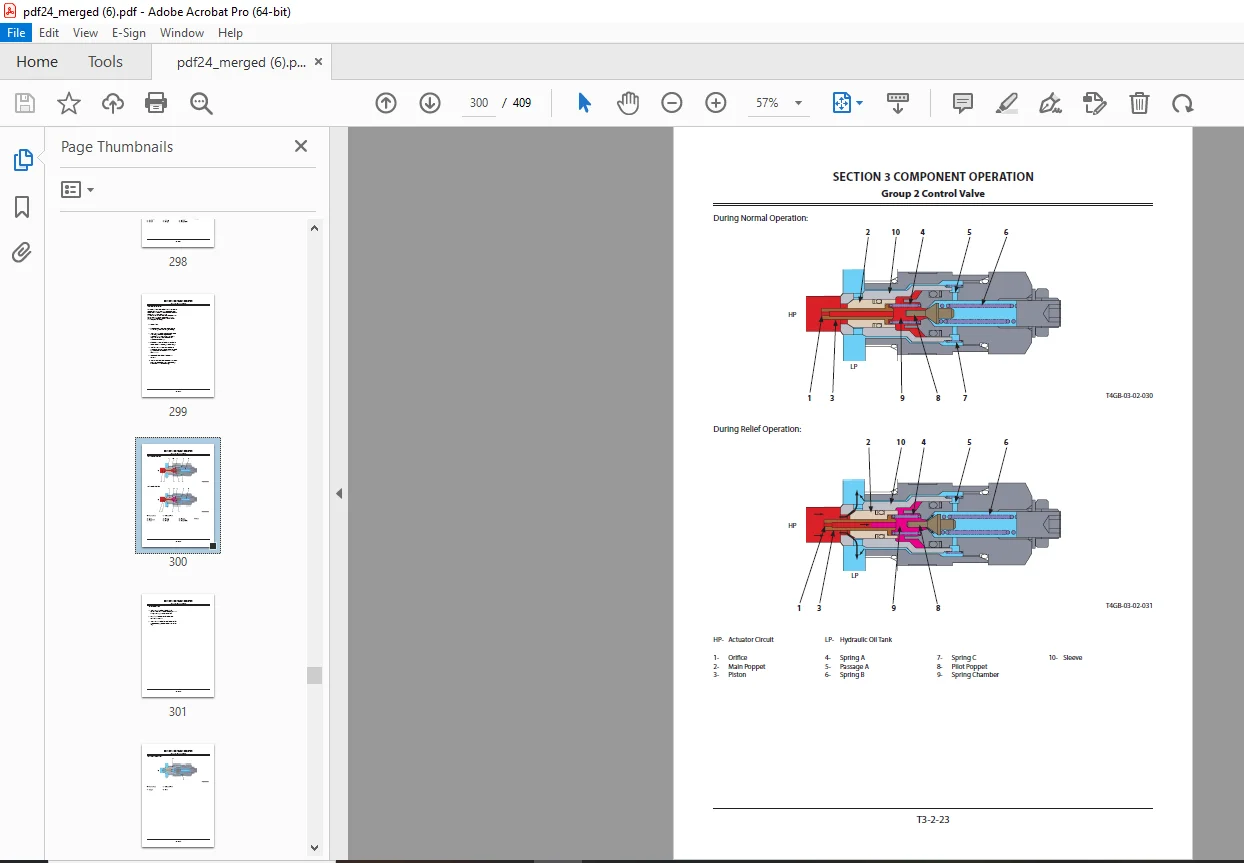
Main Relief Valve297
Overload Relief Valve299
Group 3 Priority Valve 304
Outline304
Operation305
When steering is in neutral305
When steering is operated307
When steering cylinder is at stroke end309
Group 4 Steering Valve 312
Outline312
Structure313
Operation314
Group 5 HST Motor318
Outline318
HST Motor Hydraulic Diagram319
HST Motor Layout 319
Rotary Group Part: 320
Travel Control Solenoid Valve320
Flushing Valve 320
Travel Motor 321
Regulator322
Displacement Angle Control Solenoid Valve322
Motor Displacement Angle Control 323
Travel Control Solenoid Valve325
Flushing Valve 327
Group 6 Transmission 330
Outline330
Operation331
fast speed mode331
slow speed mode332
Parking Brake333
Travel Mode Selector Valve 335
Accumulator337
Solenoid Valve 338
Travel Mode Selector Solenoid Valve338
Parking Brake Solenoid Valve 338
ON/OFF Solenoid Valve339
Group 7 Axle 340
Outline340
Differential 341
Purpose of Differential342
Principle of Differential343
Operation of Differential344
Torque Proportioning Differential (TPD)345
Limited Slip Differential (LSD) (Option) 347
Service Brake349
Final Drive / Axle Shaft 351
Group 8 Brake Valve352
Outline352
Structure353
Operation355
Group 9 Others 360
Propeller Shaft360
Inching Valve (Declutch Valve) 361
Pilot Shut-Off Solenoid Valve (Only Hydraulic Pilot Type) (Option) 362
HST Cooler Bypass Check Valve364
Pilot Accumulator (Only Hydraulic Pilot Type)(Option)365
Ride Control Accumulator (Option)366
Secondary Steering Check Block (Option)367
Secondary Steering Pump (Option) 368
Oil Filter 369
Group 10 Ride Control Valve (Option) 370
Outline370
Ride Control Hydraulic Circuit 371
Layout 372
Operation374
Charge-Cut Spool 375
Overload Relief Valve377
Drain Plug 381
Group 11 Pilot Valve (Option)382
Joystick Type Pilot Valve for FrontAttachment (Hydraulic Pilot Type) (Option)382
Outline382
Operation384
Electromagnetic Detent 391
Auxiliary Pilot Valve (Hydraulic Pilot Type)(Option) 392
Outline392
Operation393
Auxiliary Joystick Type Pilot Valve (HydraulicPilot Type) (Option) 398
Outline398
Operation399
INDEX406
Symbol and Abbreviation6
1 GENERAL8
Group 1 Specifications 8
Specifications10
Group 2 Component Layout12
Main Component (Overview) 12
Main Component (Travel System)13
Electrical System (Overview)14
Electrical System (Components Related with Relays)15
Electrical System (Components Related with Engine)15
Electrical System (Cab) 16
Engine21
Pump Device 22
Transmission/HST Motor23
Control Valve 24
Priority Valve25
Ride Control Valve (Option) 26
Secondary Steering Block (Option) 27
Secondary Steering Pump (Option)27
Pilot Shut-Off Solenoid Valve (Hydraulic Operated Type: Option) 28
Group 3 Component Specifications30
Engine30
Engine Accessories34
Hydraulic Component 36
Electrical Component41
2 SYSTEM44
Group 1 Controller46
Outline 46
CAN Circuit 47
Group 2 Control System50
Outline 50
Engine Control52
Accelerator Pedal Control 53
HST Pump Control55
HST Pump Control System Layout56
Forward/Reverse Lever Control 57
HST Brake 63
HST Motor Control 69
Driving Slow Speed Selection Control71
Traction Force Limit Control73
Traction Control75
Overrun Limit Control 77
Engine Protection Control 79
Overheat Prevention Control 81
Driving Slow Speed Switching Shock Reduction Control83
Transmission Control87
Driving Slow Speed Selection Control89
Other Controls93
Backup Light Lighting Control 95
Ride Control Function (Option)97
Parking Brake Operation Indicator Control 99
Secondary Steering Control (Option)101
Bucket Auto Leveler Control105
Lift Arm Float Control (Hydraulic Pilot Type) (Option) 109
Lift Arm Kickout Control (Hydraulic Pilot Type) (Option) 111
Group 3 ECM System 114
Outline114
Fuel Injection Control 115
EGR Control123
Neutral Engine Start Control 125
Engine Trouble Alarm Control 127
Engine Oil Pressure Alarm Control129
Overheat Alarm Control 130
Group 4 Hydraulic System 132
Outline132
Main Circuit 133
Secondary Steering Circuit (Option)143
Lift Arm, Bucket Circuit 145
HST Circuit153
Transmission Circuit 164
Clutch Circuit 164
Outline of Brake Circuit 168
Ride Control Circuit (Option)173
Pilot Circuit (Only Hydraulic Operated Type)(Option) 175
Group 5 Electrical System178
Outline178
Main Circuit 179
Accessory Circuit: 206
Wiper/Washer Circuit 207
Cab Light Circuit221
Light/Horn Circuit 224
3 COMPONENT OPERATION252
Group 1 Pump Device254
Outline254
HST Pump 255
Operational Principle256
Displacement Angle Control Cylinder257
In Neutral:258
Forward: 259
Reverse: 261
DA Valve 263
Forward/Reverse Control Solenoid Valve 264
Forward Travel 265
Reverse Travel 266
Cutoff Valve 268
Forward Operation: 269
Reverse Operation: 270
High-Pressure Relief Valve 271
Relief Operation 271
Make-Up Operation273
Low-Pressure Relief Valve275
HST Charging Pump276
Main Pump, Brake/Transmission Pump 277
Group 2 Control Valve278
Outline (Manually Operated Type) 278
Hydraulic Circuit281
Main Circuit 281
Main Relief Valve283
Overload Relief Valve (Bucket: Rod Side) 285
Outline (Hydraulic Operated Type) (Option) 290
Hydraulic Circuit293
Main Circuit 293
Pilot Operation Control Circuit295
Main Relief Valve297
Overload Relief Valve299
Group 3 Priority Valve 304
Outline304
Operation305
When steering is in neutral305
When steering is operated307
When steering cylinder is at stroke end309
Group 4 Steering Valve 312
Outline312
Structure313
Operation314
Group 5 HST Motor318
Outline318
HST Motor Hydraulic Diagram319
HST Motor Layout 319
Rotary Group Part: 320
Travel Control Solenoid Valve320
Flushing Valve 320
Travel Motor 321
Regulator322
Displacement Angle Control Solenoid Valve322
Motor Displacement Angle Control 323
Travel Control Solenoid Valve325
Flushing Valve 327
Group 6 Transmission 330
Outline330
Operation331
fast speed mode331
slow speed mode332
Parking Brake333
Travel Mode Selector Valve 335
Accumulator337
Solenoid Valve 338
Travel Mode Selector Solenoid Valve338
Parking Brake Solenoid Valve 338
ON/OFF Solenoid Valve339
Group 7 Axle 340
Outline340
Differential 341
Purpose of Differential342
Principle of Differential343
Operation of Differential344
Torque Proportioning Differential (TPD)345
Limited Slip Differential (LSD) (Option) 347
Service Brake349
Final Drive / Axle Shaft 351
Group 8 Brake Valve352
Outline352
Structure353
Operation355
Group 9 Others 360
Propeller Shaft360
Inching Valve (Declutch Valve) 361
Pilot Shut-Off Solenoid Valve (Only Hydraulic Pilot Type) (Option) 362
HST Cooler Bypass Check Valve364
Pilot Accumulator (Only Hydraulic Pilot Type)(Option)365
Ride Control Accumulator (Option)366
Secondary Steering Check Block (Option)367
Secondary Steering Pump (Option) 368
Oil Filter 369
Group 10 Ride Control Valve (Option) 370
Outline370
Ride Control Hydraulic Circuit 371
Layout 372
Operation374
Charge-Cut Spool 375
Overload Relief Valve377
Drain Plug 381
Group 11 Pilot Valve (Option)382
Joystick Type Pilot Valve for FrontAttachment (Hydraulic Pilot Type) (Option)382
Outline382
Operation384
Electromagnetic Detent 391
Auxiliary Pilot Valve (Hydraulic Pilot Type)(Option) 392
Outline392
Operation393
Auxiliary Joystick Type Pilot Valve (HydraulicPilot Type) (Option) 398
Outline398
Operation399
INDEX406
DESCRIPTION:
KCM 60Z7 Wheel Loader(General Information Function & Structure) DEUTZ TCD36 Engine Parts Manual – PDF DOWNLOAD
SN 60D1-8001 and up
PN 93206-00370
TO THE READER:
- This manual is written for an experienced technician to provide technical information needed to maintain and repair this machine.
- Be sure to thoroughly read this manual for correct product information and service procedures
MANUAL COMPOSITION:
- Our shop manuals consist of the Technical Manual, the Workshop Manual and the Engine Manual.
- Information included in the Technical Manual: Technical information needed for machine pre-delivery and delivery, operation and activation of all devices and systems, operational performance tests, and troubleshooting procedures.
- Information included in the Workshop Manual: Technical information needed for maintenance and repair of the machine, tools and devices needed for maintenance and repair, maintenance standards, and removal / installation and assembly / disassembly procedures.
- Information included in the Engine Manual: Technical information needed for machine pre-delivery and delivery and maintenance and repair of the machine, operation and activation of all devices and systems, troubleshooting and assembly / disassembly procedures.
G.B 30/01/25