KCM 67Z7B/67TM7B Wheel Loader Operation & Maintenance Manual CUMMINS QSB4.5 Engine PDF
$29.95
KCM 67Z7B/67TM7B Wheel Loader Operation & Maintenance Manual CUMMINS QSB4.5 Engine – PDF DOWNLOAD
Description
KCM 67Z7B/67TM7B Wheel Loader Operation & Maintenance Manual CUMMINS QSB4.5 Engine – PDF DOWNLOAD
FILE DETAILS:
KCM 67Z7B/67TM7B Wheel Loader Operation & Maintenance Manual CUMMINS QSB4.5 Engine – PDF DOWNLOAD
Language : English
Pages : 411
Downloadable : Yes
File Type : PDF
IMAGES PREVIEW OF THE MANUAL:
TABLE OF CONTENTS:
KCM 67Z7B/67TM7B Wheel Loader Operation & Maintenance Manual CUMMINS QSB4.5 Engine – PDF DOWNLOAD
MACHINE NUMBERS 1
Aftertreatment Device 2
SAFETY S-1
Recognize Safety Information S-1
Understand Signal Words S-1
Follow Safety Instructions S-2
Prepare for Emergencies S-3
Wear Protective ClothingS-3
Protect Against Noise S-4
Inspect Machine S-4
General Precautions for the Cab S-5
Use Handrails and Steps S-6
Never Ride Attachment S-6
Adjust Operator’s Seat S-6
Ensure Safety Before Rising from or Leaving Operator’s
Seat S-7
Fasten Your Seat Belt S-7
Move and Operate Machine Safely S-8
Handle Starting Aids Safely S-8
Operate Only from Operator’s Seat S-9
Jump Starting S-9
Investigate Job Site Beforehand S-10
Equipment of Head Guard, ROPS, FOPS S-11
Provide Signals for Jobs Involving Multiple Machines S-11
Keep Riders Off Machine S-12
Drive Safely S-12
Drive Machine Safely (Work Site) S-13
Drive Safely with Bucket Loaded S-14
Drive on Snow Safely S-14
Travel on Public Roads Safely S-15
Avoid Injury from Rollaway Accidents S-15
Avoid Accidents from Backing Up and Turning S-16
Avoid Positioning Bucket or Attachment Over
Anyone S-17
Avoid Tipping S-17
Never Undercut a High Bank S-18
Dig with Caution S-18
Perform Truck Loading Safely S-18
Avoid Power Lines S-19
Precautions for Operation S-19
Precautions for Lightning S-19
Object Handling S-20
Protect Against Flying Debris S-20
Park Machine Safely S-21
Store Attachments Safely S-21
Transport Safely S-22
Handle Fluids Safely−Avoid Fires S-23
Practice Safe Maintenance S-24
Warn Others of Service Work S-25
Support Machine Properly S-25
Stay Clear of Moving Parts S-26
Support Maintenance Properly S-26
Prevent Parts from Flying S-27
Prevent Burns S-27
Replace Rubber Hoses Periodically S-28
Avoid High-Pressure Fluids S-28
Prevent Fires S-29
Evacuating in Case of Fire S-31
Beware of Exhaust Fumes S-31
Precautions for Welding and Grinding S-32
Avoid Heating Near Pressurized Fluid Lines S-32
Avoid Applying Heat to Lines Containing Flammable
Fluids S-33
Precautions for Handling Accumulator and Gas
Damper S-33
Precautions for Diesel Exhaust Fluid (DEF) S-33
Remove Paint Before Welding or Heating S-34
Beware of Asbestos and Silica Dust and Other
Contamination S-34
Prevent Battery Explosions S-35
Service Air Conditioning System Safely S-35
Handle Chemical Products Safely S-36
Dispose of Waste Properly S-36
Notes on Aftertreatment Device S-37
Precautions for Communication Terminal S-37
Precaution for Communication Terminal Equipment S-38
SAFETY SIGNS S-41
COMPONENTS NAME 1-1
Components Name 1-1
GETTING ON/OFF THE MACHINE 1-3
Getting ON/OFF the Machine 1-3
OPERATOR’S STATION 1-4
About Aftertreatment Device 1-4
Automatic Regeneration 1-5
Cab Features 1-7
Front Console 1-8
Right Console 1-9
Multi-Function Joystick Type 1-9
Fingertip Control Type 1-10
Monitor Panel 1-11
Service Indicator 1-12
Parking Brake Indicator (Red)1-13
Brake Oil Low Pressure Indicator (Red) 1-13
Hydraulic Oil Level Indicator (Red) 1-13
Low Steering Oil Pressure Indicator (Red) 1-14
HST Warning Indicator (Red) 1-14
Discharge Warning Indicator (Red) 1-14
Urea Warning Indicator (Red) 1-14
Engine Trouble Indicator (Red) 1-15
Overheat Indicator (Red) 1-15
Engine Oil Low Pressure Indicator (Red) 1-15
Aftertreatment Device Warning Indicator 1-16
Aftertreatment Device Regeneration Request
(Blinking Yellow) 1-16
Aftertreatment Device Regeneration Inhibited Warning
Indicator 1-16
Aftertreatment Device Regeneration Inhibited
Warning (Yellow) 1-16
Aftertreatment Device Auto Regeneration Inhibited
Warning (Yellow) 1-16
CONTENTS
Air Filter Restriction Indicator (Red) 1-17
Preheat Indicator (Yellow) 1-17
Fuel Filter Restriction Indicator (Red) 1-17
HST Oil Temperature Indicator (Red) 1-17
Secondary Steering Indicator (Yellow) 1-18
Seat Belt Indicator (Red) 1-18
Water Separator Indicator (Red) 1-18
Coolant Temperature Gauge 1-19
Fuel Gauge 1-19
HST Oil Temperature Gauge 1-19
Turn Signal Indicator (Green) 1-20
High Beam Indicator (Blue) 1-20
Work Light Indicator (Yellow) 1-20
Aftertreatment Device Regeneration Inhibited
Indicator (Green) 1-20
Clearance Light Indicator (Green) 1-21
Control Lever Lock Indicator (Red) 1-21
Power Mode Indicator (Green) 1-21
Maintenance Indicator (Yellow) 1-22
Forward/Reverse Selector Switch Indicator (Green) 1-22
Fan Reverse Rotation Indicator (Green)1-22
Monitor Display 1-23
Forward/Reverse and Shift Position Indicator 1-24
Speedometer 1-26
Ride Control Indicator (Optional) 1-27
ECO Indicator 1-27
DEF Level Gauge 1-27
DEF/SCR System Alarm 1-28
DEF Level Alarm 1-28
Urea SCR System Malfunction 1-29
Machine Information Display 1-30
Shifting Item to be Indicated on Machine
Information Display 1-31
Resetting of Oil Change and Filter Replacement
Intervals 1-37
Hydraulic Oil Change Interval Hour Meter 1-37
Hydraulic Oil Filter 1 Replacement Interval
Hour Meter 1-38
Hydraulic Oil Filter 2 Replacement Interval
Hour Meter 1-39
Hydraulic Oil Filter 3 Replacement Interval
Hour Meter 1-40
Transmission Oil Change Interval Hour Meter 1-41
Transmission Oil Filter Replacement Interval
Hour Meter 1-42
Engine Oil Change Interval Hour Meter 1-43
Engine Oil Filter Replacement Interval Hour Meter 1-44
Oil Separator Element Replacement Interval
Hour Meter 1-45
Fuel Filter Replacement Interval Hour Meter 1-46
DEF Supply Module Main Filter
Replacement Interval Hour Meter 1-47
Axle Oil Change Interval Hour Meter 1-48
Clock Setting Mode 1-49
Clock (24H) Setting Procedures 1-49
Switches, Steering Wheel and Pedals 1-50
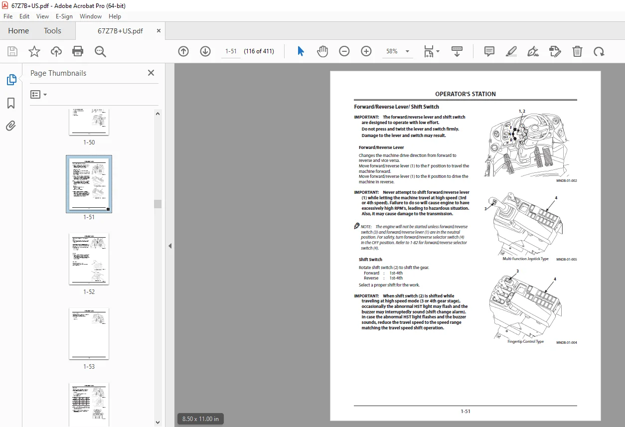
Forward/Reverse Lever/ Shift Switch 1-51
Forward/Reverse Lever 1-51
Shift Switch 1-51
Neutral Lever Lock (for the Forward/Reverse Lever) 1-52
Steering 1-52
Horn Switch 1-52
Turn Signal Lever 1-53
Light Switch 1-54
High-Low Beam Switch 1-55
Key Switch 1-55
Wiper Switch 1-56
Wiper Operation 1-56
Front/Rear Wiper Switch 1-57
Hazard Switch 1-58
Work Light Switch 1-59
Parking Brake Switch 1-60
Accelerator Pedal 1-61
Brake Pedal 1-61
Tilt, Telescopic Lever/Steering Column Tilt Pedal 1-62
1st Speed Select Switch 1-63
Auto Idling Stop Switch 1-64
Right Console / Switches 1-65
Multi-Function Joystick Type 1-65
Multi-Function Joystick Lever 1-66
Right Console / Switches 1-67
Fingertip Control Type 1-67
Control Lever 1-68
Control Lever Lock Switch 1-70
Armrest Adjust Handle 1-71
Creep Mode Switch 1-72
Traction Control Switch 1-73
Power Mode Switch 1-74
Aftertreatment Device Regeneration Switch 1-75
Manual Regeneration Procedure 1-76
Aftertreatment Device Regeneration Inhibited 1-78
Ride Control Switch (Optional) 1-79
AUTO1-79
OFF 1-79
Fan Reverse Rotation Switch 1-80
Manual Operation 1-80
AUTO 1-81
Forward/Reverse Selector Switch 1-82
Operational Procedure 1-82
Secondary Steering Operation Check Switch (Optional)
1-83
Dual Lift Arm Auto Leveler 1-84
Cigar Lighter (24 VDC Electrical Outlet) 1-85
Using Cigar Lighter 1-85
Using Cigar Lighter Port as External Power Source 1-85
Ash Tray 1-86
Auto Air Conditioner 1-87
Feature 1-87
Components Name 1-88
Controller Part Name and Function 1-89
Mode/Temperature Control Switch 1-91
CONTENTS
Defroster Operation 1-93
Cool Head/Warm Feet Operation 1-93
Tips for Optimal Air Conditioner Usage 1-94
For Rapid Cooling 1-94
When Windows Become Clouded 1-94
Off-Season Air Conditioner Maintenance 1-94
Adjusting Operator’s Seat (Air Suspension Type Seat) 1-95
Components Name 1-95
Rear Tray 1-96
Electric Power Output (12 VDC Electrical Outlet) 1-96
Fuse Box 1-97
Fuse Box A 1-98
Fuse Box B 1-98
Hot/Cool Box 1-99
Tray and Drink Holder 1-99
ROPS Cab 1-100
Front Room Light1-102
Rear Room Light 1-102
Emergency Evacuation Hammer 1-102
Sun Visor 1-103
Coat Hook 1-103
Upper Switch Panel 1-104
Rotary Light Switch (Optional) 1-104
Rear View Mirror Heater Switch 1-104
Outside Rear View Mirror 1-105
Room Rear View Mirror 1-105
Cab Door 1-105
Door Lock Knob 1-106
Door Open/Close Lever 1-106
Window Open/Close Levers 1-106
When Fully Opening the Door 1-107
Cab Door Release Lever 1-107
Battery Disconnect Switch 1-108
Switch Operation 1-109
Articulation Lock Bar 1-110
Towing Pin 1-111
Inspection/Maintenance Side Access Cover 1-112
Steps1-113
Tool Box 1-113
Vandal-Proof Devices 1-114
Seat Belt 1-116
Seat Pocket 1-116
Rear View Camera Monitor 1-117
Components Name 1-117
Starting and Stopping the Rear View Camera
Monitor 1-117
Monitor Setting and Adjustment 1-118
BREAK-IN 2-1
Break-in Period for New Machine 2-1
Work Mode for Break-in 2-1
OPERATING ENGINE 3-1
Inspect Machine Daily Before Starting 3-1
Check Before Starting 3-3
Starting Engine 3-5
Starting in Cold Weather3-7
Check After Starting 3-8
Using Booster Batteries 3-9
Warm Up 3-11
Cold Weather Warm Up 3-12
Stopping Engine 3-14
DRIVING MACHINE 4-1
Driving the Machine 4-1
Starting to Move 4-2
Parking Brake Switch 4-4
Drive Speed Change4-5
Changing Forward/Reverse Drive Direction 4-5
Steering Wheel 4-6
Secondary Steering (Optional) 4-7
Emergency Stop and Restart of Driving 4-8
Precautions for Driving on Slopes 4-11
Precautions for Driving Speeds 4-12
Precautions to be Taken if Machine Failure Occurs 4-13
Stop the Machine 4-14
Parking 4-16
Emergency Stopping 4-17
OPERATING MACHINE 5-1
Control Lever 5-1
Control Lever Lock Switch 5-4
Ride Control Switch (Optional) 5-5
Lift Arm Kick Out 5-7
Dual Lift Arm Auto Leveler 5-8
Bucket Auto Leveler5-9
Auto Idling Stop 5-11
Before Operation 5-13
Precautions for Operation 5-13
Ensure Safety When Operating on Road Shoulders 5-13
Avoid Overloading 5-14
Avoid Rapid Steering Changes and/or Sudden
Braking 5-14
Avoid Operation with Biased Loads 5-14
Excavation 5-15
Grading 5-17
Loading 5-18
Dozing 5-21
Scooping 5-21
Removing Snow 5-22
Lifting Wheel Loader 5-22
Precautions for After Operations 5-23
TRANSPORTING 6-1
Transporting by Road 6-1
Transporting by Trailer 6-1
Loading / Unloading on Trailer 6-2
Fastening Machine for Transporting 6-4
Transporting Wheel Loader (Urgent Situation) 6-5
Towing Method 6-10
Lifting Machine 6-11
MAINTENANCE 7-1
Correct Maintenance and Inspection Procedures 7-1
Check the Hour Meter Regularly 7-2
CONTENTS
Layout 7-3
Preparations for Inspection and Maintenance 7-7
Lock Frames 7-9
Inspection/Maintenance Access Side Cover 7-10
Inspection and Maintenance Table 7-11
Kind of Oils 7-17
List of Consumable Parts 7-21
A Greasing 7-24
B Engine 7-30
Check Engine Oil Level 7-30
Change Engine Oil 7-31
Replace Engine Oil Filter 7-33
Check Crankcase Breather Tube 7-34
Replace Crankcase Breather Filter Element 7-35
Check Oil Drain Tube 7-36
C Power Train 7-37
Check Transmission Oil Level 7-37
Change Transmission Oil 7-38
Clean Transmission Strainer 7-38
Replace Transmission Oil Filter 7-40
Change Axle Oil 7-41
Check Oil Level 7-42
Check Surroundings Around Axle and Covers for Oil
Leaks 7-43
Clean Transmission Air Breather 7-43
D Hydraulic System 7-44
Inspection and Maintenance of Hydraulic Equipment 7-44
Check Hydraulic Oil Level 7-46
Change Hydraulic Oil/Clean Hydraulic Oil Tank 7-47
Bleed Air from the Hydraulic System 7-48
Bleed Air from the Hydraulic Circuit7-48
Clean Suction Filter 7-49
Replace Pilot Oil Filter7-50
Replace Hydraulic Tank Oil Filter 7-52
Replace HST Charge Filter 7-54
Replace Air Breather Element 7-55
Check Pilot Circuit Accumulator Function, Gas
Leakage, Looseness, and Damage 7-56
Replace Pilot Circuit Accumulator 7-57
Check Ride Control Accumulator Function, Gas
Leakage, Looseness, and Damage (Optional) 7-57
Check Gas Pressure in Ride Control Accumulator
(Optional) 7-57
Check Gas Pressure in Steering Accumulator 7-57
Check Hoses and Lines 7-58
E Fuel System 7-63
Check Fuel Level 7-63
Drain Water and Sediment from Fuel Tank 7-65
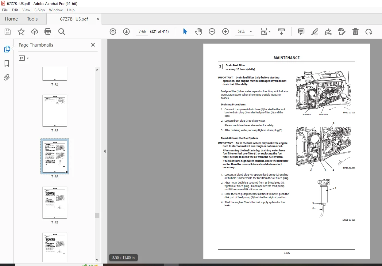
Drain Fuel Filter 7-66
Bleed Air from the Fuel System 7-66
Replace Fuel Main Filter Element 7-67
Replace Fuel Pre-Filter Element 7-68
Clean Fuel Solenoid Pump Strainer 7-69
Check Fuel Hoses 7-70
F Air Cleaner 7-71
Clean and Replace Air Cleaner Element 7-71
G Cooling System 7-72
Coolant 7-72
Precautions for handling antifreeze 7-72
Check Coolant Level 7-73
Check Drive Belt 7-74
Check Drive Belt Tensioner 7-75
Change Coolant 7-76
Clean Radiator/Oil Cooler and Other Cooling
System 7-77
H Electrical System 7-78
Batteries 7-78
Check Monitor Functions and All Other Instrument
Operation 7-82
Check Lights 7-83
Check Horn and Reverse Buzzer 7-83
Check Electrical Harnesses and Fuses 7-84
I Brake System 7-86
Check Right and Left Brake Interlocking
Performance 7-86
Check Parking Brake Force 7-87
Check Accumulator Function, Gas Leakage,
Looseness, and Damage 7-88
Check Gas Pressure in Accumulator 7-89
Check Brake Disks (Service and Parking) 7-89
J Tire 7-90
Check and Replace Tire (Tire Pressure) 7-90
Check Tire for Damage 7-90
Check Wheel Bolt Torque 7-91
Removal and Installation of Tire 7-94
K Air Conditioner 7-95
Clean/Replace Air Conditioner Circulation/Fresh Air
Filters 7-95
Check Air Conditioner 7-99
Check Air Conditioner Piping 7-99
Check Air Conditioner Condenser 7-100
Check Air Conditioner Fan Belt 7-100
Check Refrigerant 7-101
Check Compressor and Pulley 7-101
L Miscellaneous 7-102
Check Bucket Teeth and Cutting Edge 7-102
Check and Replace Seat and Seat Belt 7-103
Check ROPS Cab Mounting Bolts 7-103
Check Windshield Washer Fluid Level 7-103
Check Play Amount in Steering Wheel Stroke 7-104
Check Accelerator Pedal Operation, and Exhaust
Gas Color and Noise 7-105
Check Rearview Mirror and Inside Rearview
Mirror 7-106
Check Steps and Handrails for Damage and
Looseness 7-106
Clean Engine Compartment and Hood 7-107
Check Sound Absorbing Mat Around Engine 7-107
Check and Adjust Valve Clearance 7-108
Retighten Front Axle and Rear Axle Support
Mounting Bolts 7-108
CONTENTS
Tightening and Retightening Torque of Nuts and
Bolts 7-109
M Aftertreatment Device 7-121
Check and Clean Aftertreatment Device 7-121
N Urea SCR System 7-122
Check DEF 7-124
Replace DEF Supply Module Main Filter 7-127
MAINTENANCE UNDER SPECIAL ENVIRONMENTAL
CONDITIONS 9-1
Maintenance Under Special Environmental Conditions 9-1
Precautions for Maintenance During Cold Weather
Season 9-2
STORAGE 10-1
Storing the Machine 10-1
TROUBLESHOOTING 11-1
Troubleshooting 11-1
SPECIFICATIONS 12-1
Specifications 12-1
OPTIONAL ATTACHMENTS 13-1
Hydraulic Type Quick Coupler Operation 13-1
INDEX 14-1
DESCRIPTION:
KCM 67Z7B/67TM7B Wheel Loader Operation & Maintenance Manual CUMMINS QSB4.5 Engine – PDF DOWNLOAD
- Read this manual carefully before starting and operating the machine for the first time to learn how to operate and service your machine correctly. Failure to do so could result in personal injury or machine damage.
- This standard specification machine can be operated under the following conditions without being modified. Atmospheric Temperature: -20 °C to 45 °C (-4 °F to 113 °F) Altitude: 0 m to 2000 m (0 ft to 6600 ft) In case the machine is used under conditions other than described above, consult your nearest authorized dealer.
- This manual should be considered a permanent part of your machine and should remain with the machine when you sell it. Replace immediately if missing, damaged or not readable.
- This machine is of metric design. Measurements in this manual are metric. American standard measurements are included when appropriate. Use only metric hardware and tools as specified.
- Right-hand and left-hand sides are determined by facing in the direction of forward travel.
- Write product identification numbers in the Machine Numbers section. Accurately record all the numbers to help in tracing the machine should it be stolen. Your dealer also needs these numbers when you order parts. If this manual is kept on the machine, also file the identification numbers in a secure place off the machine. Use only diesel fuel with quality specified in JIS K-2204, EN-590 or ASTM D-975 which contents 15 ppm or lower sulfur. Also use fuel that complies with solid contamination level of class 18/16/13 of ISO4406-1999 (solid contamination includes dust). If the fuel specified above is not used, exhaust gas that exceeds the regulation values may be discharged, causing serious problem on the engine. Consult your nearest authorized dealer.
G.B 01/02/25