KCM 70Z6 WHEEL LOADER Shop Manual Serial No.70C7-0101 and up – PDF
$32.95
KCM 70Z6 WHEEL LOADER Shop Manual Serial No.70C7-0101 and up -PDF DOWNLOAD
Description
KCM 70Z6 WHEEL LOADER Shop Manual Serial No.70C7-0101 and up -PDF DOWNLOAD
FILE DETAILS:
KCM 70Z6 WHEEL LOADER Shop Manual Serial No.70C7-0101 and up -PDF DOWNLOAD
Language : English
Pages : 743
Downloadable : Yes
File Type : PDF
IMAGES PREVIEW OF THE MANUAL:
TABLE OF CONTENTS:
KCM 70Z6 WHEEL LOADER Shop Manual Serial No.70C7-0101 and up -PDF DOWNLOAD
INTRODUCTIONIN-01
Additional References IN-01
Manual CompositionIN-01
Page Number IN-01
Safety Alert Symbol and Headline Notations IN-02
Units Used IN-02
Symbol and AbbreviationSY-1
Symbol and Abbreviation SY-1
SAFETY SA-1
Recognize Safety InformationSA-1
Understand Signal Words SA-1
Follow Safety InstructionsSA-2
Prepare for Emergencies SA-3
Wear Protective Clothing SA-3
Protect Against NoiseSA-4
Inspect MachineSA-4
General Precautions for CabSA-5
Use Handrails and Steps SA-6
Never Ride Attachment SA-6
Adjust Operator’s Seat SA-6
Ensure Safety Before Rising from or Leaving
Operator’s Seat SA-7
Fasten Your Seat BeltSA-7
Move and Operate Machine Safely SA-8
Handle Starting Aids Safely SA-8
Operate Only from Operator’s SeatSA-9
Jump Starting SA-9
Investigate Job Site BeforehandSA-10
Equipment of Head Guard, ROPS, FOPSSA-11
Provide Signals for Jobs Involving Multiple Machines
SA-11
Keep Riders Off MachineSA-12
Drive SafelySA-12
Drive Machine Safely (Work Site) SA-13
Drive Safely with Bucket Loaded SA-14
Drive on Snow Safely SA-14
Travel on Public Roads SafelySA-15
Avoid Injury from Rollaway Accidents SA-15
Avoid Accidents from Backing Up and Turning SA-16
Avoid Positioning Bucket or Attachment Over Anyone
SA-17
Avoid TippingSA-17
Never Undercut a High Bank SA-18
Dig with CautionSA-18
Perform Truck Loading Safely SA-18
Avoid Power Lines SA-19
Precautions for OperationSA-19
Precautions for Lightning SA-19
Object HandlingSA-20
Protect Against Flying Debris SA-20
Park Machine SafelySA-21
Store Attachments Safely SA-21
Transport Safely SA-22
Handle Fluids Safely−Avoid FiresSA-23
Practice Safe Maintenance SA-24
Warn Others of Service WorkSA-25
Support Machine Properly SA-25
Stay Clear of Moving Parts SA-26
Support Maintenance ProperlySA-26
Prevent Parts from Flying SA-27
Prevent BurnsSA-27
Replace Rubber Hoses Periodically SA-28
Avoid High-Pressure FluidsSA-28
Prevent FiresSA-29
Evacuating in Case of Fire SA-31
Beware of Exhaust FumesSA-31
Precautions for Welding and GrindingSA-31
Avoid Heating Near Pressurized Fluid LinesSA-32
Avoid Applying Heat to Lines Containing
Flammable Fluids SA-32
Precautions for Handling Accumulator and Gas
DamperSA-32
Remove Paint Before Welding or HeatingSA-33
Beware of Asbestos and Silicon Dust and Other
ContaminationSA-33
Prevent Battery ExplosionsSA-34
Service Air Conditioning System SafelySA-34
Handle Chemical Products SafelySA-35
Dispose of Waste ProperlySA-35
Precautions for Communication TerminalSA-36
Precaution for Communication Terminal Equipment
(Option) SA-37
Before Returning the Machine to the CustomerSA-39
SECTION 1 GENERAL W1-1-1-1
Group 1 Precautions for Disassembling and
Assembling W1-1-1-1
Precautions for Disassembling and Assembling W1-1-1-1
Precautions for Disassembling W1-1-1-1
Precautions for Disassembling and Assembling
W1-1-1-1
Precautions for Using Floating Seal W1-1-1-2
Precautions for Using Nylon SlingW1-1-1-3
Maintenance Standard Terminology W1-1-1-5
Group 2 TighteningW1-2-1-1
Tightening Bolts and NutsW1-2-1-1
Bolt Types W1-2-1-1
Specified Tightening Torque Chart W1-2-1-1
Tightening OrderW1-2-1-2
Precautions for Spilt FlangeW1-2-1-3
Nut and Bolt Locking W1-2-1-3
Piping Joint W1-2-1-4
Union JointW1-2-1-5
Pipe Joint W1-2-1-6
O-ring Seal JointW1-2-1-6
Quick CouplingW1-2-1-7
Screw-In Connection W1-2-1-8
Seal Tape ApplicationW1-2-1-8
Low-Pressure-Hose Clamp TighteningW1-2-1-8
Connecting HoseW1-2-1-9
CONTENTS
ii
Group 3 Painting W1-3-1-1
PaintingW1-3-1-1
Group 4 Bleeding AirW1-4-1-1
Bleeding Air from Hydraulic Oil TankW1-4-1-1
PreparationW1-4-1-1
Bleeding Air from Hydraulic SystemW1-4-1-2
Bleeding Air from Fuel SystemW1-4-1-3
Bleeding Air from Radiator W1-4-1-4
PreparationW1-4-1-4
Bleeding Air from Brake (Axle) W1-4-1-5
Group 5 Releasing Pressure W1-5-1-1
Front Attachment Hydraulic Circuit Pressure Release
ProcedureW1-5-1-1
Ride Control Accumulator Pressure Release
ProcedureW1-5-1-2
Parking Brake Accumulator Pressure Release
ProcedureW1-5-1-3
Group 6 Preparation W1-6-1-1
Preparation before Inspection and Maintenance
W1-6-1-1
Lock of Frame W1-6-1-2
Machine Position for Inspection and
Maintenance (lift arm raise) W1-6-1-3
SECTION 2 MAINTENANCE STANDARD W2-1-1-1
Group 1 BodyW2-1-1-1
Center HingeW2-1-1-1
Group 2 Front Attachment W2-2-1-1
Pin and BushingW2-2-1-1
Standard Dimensions for Lift Arm and BucketW2-2-2-1
CylinderW2-2-3-1
Rod W2-2-3-1
Rod Bend and Run Out W2-2-3-1
SECTION 3 BODY W3-1-1-1
Group 1 CabW3-1-1-1
Removal and Installation of Cab W3-1-1-1
RemovalW3-1-1-1
InstallationW3-1-1-17
Group 2 Counterweight W3-2-1-1
Removal and Installation of CounterweightW3-2-1-1
RemovalW3-2-1-1
Installation W3-2-1-2
Removal and Installation of Battery BoxW3-2-2-1
RemovalW3-2-2-1
Removal of Battery Box (Right)W3-2-2-1
Removal of Battery Box (Left) W3-2-2-2
Installation W3-2-2-3
Installation of Battery Box (Left)W3-2-2-3
Installation of Battery Box (Right) W3-2-2-4
Group 3 Center Hinge W3-3-1-1
Removal and Installation of Center HingeW3-3-1-1
RemovalW3-3-1-1
InstallationW3-3-1-13
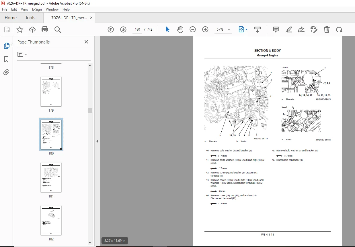
Group 4 Engine W3-4-1-1
Removal and Installation of Engine W3-4-1-1
RemovalW3-4-1-1
InstallationW3-4-1-22
Removal And Installation of Exterior PartsW3-4-2-1
Removal and Installation of Engine Cover (34), Rear Cover
(42), and Covers (Lower) (29, 30)W3-4-2-2
Removal and Installation of Side Covers (Front) (1, 2)
W3-4-2-4
Removal and Installation of Front Fenders (1, 2)
W3-4-2-6
Removal and Installation of Rear Fenders (39, 40), Deck
(01), and Steps (Front) (51, 52, 53) W3-4-2-7
Removal and Installation of Rear Grill (1) W3-4-2-9
Removal and Installation of Inspection Covers (1, 2, 4)
and Steps (Rear) (35, 36, 40) W3-4-2-10
Removal and Installation of Side Covers (Rear) (01, 02)
W3-4-2-11
Group 5 Radiator Assembly W3-5-1-1
Removal and Installation of Radiator, Oil Cooler, Intercooler,
and Torque Converter Cooler W3-5-1-1
RemovalW3-5-1-1
InstallationW3-5-1-15
Group 6 Hydraulic Oil TankW3-6-1-1
Removal and Installation of Hydraulic Oil Tank W3-6-1-1
RemovalW3-6-1-1
InstallationW3-6-1-11
Group 7 Fuel Tank W3-7-1-1
Removal and Installation of Fuel TankW3-7-1-1
RemovalW3-7-1-1
Installation W3-7-1-4
Group 8 Pump Device W3-8-1-1
Removal and Installation of Pump DeviceW3-8-1-1
RemovalW3-8-1-1
Installation W3-8-1-5
Disassembly of Pump Device W3-8-2-1
Disassembly of Pump Device W3-8-2-2
Assembly of Pump DeviceW3-8-2-3
Assembly of Pump Device W3-8-2-4
Disassembly of Main PumpW3-8-3-1
Disassembly of Main Pump W3-8-3-2
Assembly of Main PumpW3-8-3-5
Assembly of Main Pump W3-8-3-7
Disassembly of RegulatorW3-8-4-1
Disassembly of RegulatorW3-8-4-2
Assembly of Regulator W3-8-4-3
Assembly of RegulatorW3-8-4-4
Structure of Pilot PumpW3-8-5-1
CONTENTS
iii
Group 9 Control ValveW3-9-1-1
Removal and Installation of Control ValveW3-9-1-1
RemovalW3-9-1-1
Installation W3-9-1-6
Disassembly of Control Valve W3-9-2-1
Disassembly of Control Valve W3-9-2-2
Assembly of Control ValveW3-9-2-5
Assembly of Control Valve W3-9-2-8
Group 10 Pilot Valve W3-10-1-1
Removal and Installation of Pilot Valve W3-10-1-1
Removal W3-10-1-1
InstallationW3-10-1-4
Removal and Installation of Pilot Valve
(Two Lever Type)W3-10-2-1
Removal W3-10-2-1
InstallationW3-10-2-4
Disassembly of Pilot ValveW3-10-3-1
Disassembly of Pilot ValveW3-10-3-2
Assembly of Pilot Valve W3-10-3-4
Assembly of Pilot ValveW3-10-3-5
Disassembly of Pilot Valve (Two Lever Type) W3-10-4-1
Disassembly of Pilot Valve (Two Lever Type)W3-10-4-3
Assembly of Pilot Valve (Two Lever Type) W3-10-4-7
Assembly of Pilot Valve (Two Lever Type) W3-10-4-9
Group 11 Brake Charge ValveW3-11-1-1
Removal and Installation of Brake Charge Valve
W3-11-1-1
Removal W3-11-1-1
InstallationW3-11-1-4
Structure of Brake Charge Valve W3-11-2-1
Structure of Brake Charge Valve W3-11-2-2
Removal and Installation of Brake Accumulator
W3-11-3-1
Removal W3-11-3-1
InstallationW3-11-3-4
Group 12 Manifold Valve W3-12-1-1
Removal and Installation of Manifold ValveW3-12-1-1
Removal W3-12-1-1
InstallationW3-12-1-6
Disassembly of Manifold Valve W3-12-2-1
Disassembly of Manifold Valve W3-12-2-2
Assembly of Manifold Valve W3-12-2-4
Assembly of Manifold Valve W3-12-2-6
Group 13 Solenoid ValveW3-13-1-1
Removal and Installation of Parking Brake
Solenoid Valve Unit W3-13-1-1
Removal W3-13-1-1
InstallationW3-13-1-3
Structure of Parking Brake Solenoid Valve Unit W3-13-2-1
Group 14 Priority ValveW3-14-1-1
Removal and Installation of Priority ValveW3-14-1-1
Removal W3-14-1-1
InstallationW3-14-1-6
Structure of Priority Valve W3-14-2-1
Group 15 Cooling Fan System W3-15-1-1
Removal and Installation of Fan Motor W3-15-1-1
Removal W3-15-1-1
InstallationW3-15-1-8
Structure of Fan MotorW3-15-2-1
Removal and Installation of Fan PumpW3-15-3-1
Removal W3-15-3-1
InstallationW3-15-3-4
Disassembly of Fan PumpW3-15-4-1
Disassembly of Fan Pump W3-15-4-2
Assembly of Fan PumpW3-15-4-3
Assembly of Fan PumpW3-15-4-4
Group 16 Ride Control Device W3-16-1-1
Removal and Installation of Ride Control Valve W3-16-1-1
Removal W3-16-1-1
InstallationW3-16-1-3
Disassembly of Ride Control ValveW3-16-2-1
Disassembly of Ride Control ValveW3-16-2-2
Assembly of Ride Control ValveW3-16-2-4
Assembly of Ride Control ValveW3-16-2-6
Removal and Installation of Ride Control
AccumulatorW3-16-3-1
Removal W3-16-3-1
InstallationW3-16-3-3
SECTION 4 TRAVEL SYSTEM W4-1-1-1
Group 1 Tire W4-1-1-1
Removal and Installation of Front TireW4-1-1-1
RemovalW4-1-1-1
Installation W4-1-1-2
Applicable Tire SizeW4-1-1-3
Removal and Installation of Rear TireW4-1-2-1
RemovalW4-1-2-1
Installation W4-1-2-2
Applicable Tire SizeW4-1-2-3
Group 2 Drive UnitW4-2-1-1
Removal and Installation of Drive Unit W4-2-1-1
RemovalW4-2-1-1
Installation W4-2-1-4
Disassembly and Assembly of Drive UnitW4-2-2-1
Drive Unit AssemblyW4-2-2-1
Detail of Transmission Assembly (2) W4-2-2-2
Removal and Installation of Oil Filter W4-2-2-4
Removal of Oil Filter W4-2-2-5
Installation of Oil FilterW4-2-2-6
Removal and Installation of Torque ConverterW4-2-3-1
Removal of Torque Converter W4-2-3-2
Installation of Torque ConverterW4-2-3-3
Installation of Torque ConverterW4-2-3-4
Disassembly and Assembly of TransmissionW4-2-4-1
Disassembly and Assembly of Hydraulic Pump
Drive W4-2-4-1
Removal of Hydraulic Pump DriveW4-2-4-3
CONTENTS
iv
Assembly of Hydraulic Pump DriveW4-2-4-6
Removal and Installation of Clutch W4-2-4-11
Removal of Clutch, Input Shaft, and
Output ShaftW4-2-4-11
Installation of Clutch, Input Shaft, and
Output ShaftW4-2-4-17
Disassembly and Assembly of Clutch W4-2-4-24
Disassembly of First Speed Clutch (K1), Second Speed
Clutch (K2), and Third Speed Clutch (K3) W4-2-4-27
Assembly of First Speed Clutch (K1), Second Speed Clutch
(K2), and Third Speed Clutch (K3) W4-2-4-31
Disassembly of Slow-Speed Forward Clutch (KV) and
Reverse Clutch (KR)W4-2-4-36
Assembly of Slow-Speed Forward Clutch (KV) and
Reverse Clutch (KR)W4-2-4-38
Disassembly of Fast-Speed Forward Clutch (K4)
W4-2-4-43
Assembly of Fast-Speed Forward Clutch (K4)
W4-2-4-45
Disassembly and Assembly of Transmission
Control ValveW4-2-5-1
Removal and Installation of Transmission
Control Valve W4-2-5-1
Removal of Transmission Control ValveW4-2-5-2
Installation of Transmission Control Valve W4-2-5-3
Removal and Installation of Duct Plate W4-2-5-4
Removal of Duct Plate W4-2-5-5
Assembly of Duct Plate W4-2-5-6
Disassembly and Assembly of Transmission
Control Valve W4-2-5-7
Disassembly of Transmission Control ValveW4-2-5-8
Assembly of Transmission Control ValveW4-2-5-9
Removal and Installation of Parking Brake (Replace The
Brake Friction Pad)W4-2-6-1
RemovalW4-2-6-1
Installation W4-2-6-3
Adjustment of parking brake W4-2-6-5
The manual release of the parking brake W4-2-6-6
Removal and Installation of Flange at Output
Shaft Side W4-2-6-7
RemovalW4-2-6-7
Installation W4-2-6-8
Group 3 Axle W4-3-1-1
Removal and Installation of Front AxleW4-3-1-1
RemovalW4-3-1-1
Installation W4-3-1-4
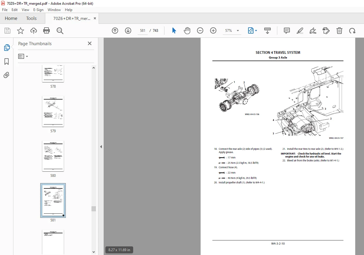
Removal and Installation of Rear AxleW4-3-2-1
RemovalW4-3-2-1
Installation W4-3-2-5
Disassembly of Axle W4-3-3-1
Disassembly of Axle W4-3-3-1
Assembly of AxleW4-3-3-2
Assembly of Axle W4-3-3-2
Group 4 Propeller Shaft W4-4-1-1
Removal and Installation of Propeller Shaft W4-4-1-1
RemovalW4-4-1-1
Installation W4-4-1-6
Group 5 Brake Valve W4-5-1-1
Removal and Installation of Brake Valve
(One Pedal)W4-5-1-1
RemovalW4-5-1-1
Installation W4-5-1-3
Removal and Installation of Brake Valve
(Two Pedals)W4-5-2-1
RemovalW4-5-2-1
Installation W4-5-2-3
Disassembly of Brake Valve W4-5-3-1
Disassembly of Brake Valve W4-5-3-2
Assembly of Brake ValveW4-5-3-4
Assembly of Brake Valve W4-5-3-7
Group 6 Steering DeviceW4-6-1-1
Removal and Installation of Steering ValveW4-6-1-1
RemovalW4-6-1-1
Installation W4-6-1-3
Disassembly of Steering Valve W4-6-2-1
Disassembly of Steering Valve W4-6-2-2
Assembly of Steering Valve W4-6-2-4
Assembly of Steering Valve W4-6-2-6
Removal and Installation of Steering CylinderW4-6-3-1
RemovalW4-6-3-1
Removal of Steering Cylinder (Left) W4-6-3-1
Removal of Steering Cylinder (Right)W4-6-3-4
Installation W4-6-3-7
Installation of Steering Cylinder (Right) W4-6-3-7
Installation of Steering Cylinder (Left) W4-6-3-11
Disassembly of Steering Cylinder W4-6-4-1
Disassembly of Steering Cylinder W4-6-4-2
Assembly of Steering CylinderW4-6-4-5
Assembly of Steering Cylinder W4-6-4-6
Removal and Installation of Steering Accumulator
W4-6-5-1
RemovalW4-6-5-1
Installation W4-6-5-2
Group 7 Emergency Steering DeviceW4-7-1-1
Removal and Installation of Emergency
Steering Pump W4-7-1-1
RemovalW4-7-1-1
Installation W4-7-1-4
SECTION 5 FRONT ATTACHMENTW5-1-1-1
Group 1 Front Attachment W5-1-1-1
Removal and Installation of Front Attachment
(With Lift Arm Kickout) W5-1-1-1
RemovalW5-1-1-1
Position to Install (Lift Arm) W5-1-1-6
Installation W5-1-1-6
Direction to Install (Lift Arm)W5-1-1-6
Position to Install (Bucket Cylinder) W5-1-1-7
CONTENTS
v
Direction to Install (Bucket Cylinder) W5-1-1-7
Removal and Installation of Front Attachment
(With Lift Arm Auto Leveler) W5-1-2-1
RemovalW5-1-2-1
Position to Install (Lift Arm) W5-1-2-7
Installation W5-1-2-7
Direction to Install (Lift Arm)W5-1-2-7
Position to Install (Bucket Cylinder) W5-1-2-8
Direction to Install (Bucket Cylinder) W5-1-2-8
Removal and Installation of Bell Crank W5-1-3-1
Position to Install (Bell Crank) W5-1-3-4
Installation W5-1-3-4
Direction to Install (Bell Crank)W5-1-3-4
Position to Install (Bucket Link)W5-1-3-5
Direction to Install (Bucket Link) W5-1-3-5
Position to Install (Bucket Cylinder) W5-1-3-6
Direction to Install (Bucket Cylinder) W5-1-3-6
Removal and Installation of Bucket W5-1-4-1
RemovalW5-1-4-1
Position to Install (Lift Arm) W5-1-4-3
Installation W5-1-4-3
Direction to Install (Lift Arm)W5-1-4-3
Direction of Install (Bucket Link) W5-1-4-4
Direction to Install (Bucket Link) W5-1-4-4
Group 2 Cylinder W5-2-1-1
Removal and Installation of Lift Arm Cylinder W5-2-1-1
RemovalW5-2-1-1
Position to Install (Lift Arm Cylinder) W5-2-1-4
Installation W5-2-1-4
Direction to Install (Lift Arm Cylinder) W5-2-1-4
Removal and Installation of Bucket Cylinder W5-2-2-1
RemovalW5-2-2-1
Position to Install (Bucket Cylinder) W5-2-2-6
Installation W5-2-2-6
Direction to Install (Bucket Cylinder) W5-2-2-6
Disassembly of Lift Arm Cylinder and Bucket
CylinderW5-2-3-1
Lift Arm Cylinder W5-2-3-1
Bucket CylinderW5-2-3-2
Disassembly of Lift Arm Cylinder and Bucket
Cylinder W5-2-3-3
Assembly of Lift Arm Cylinder and Bucket Cylinder
W5-2-3-6
Lift Arm Cylinder W5-2-3-6
Bucket CylinderW5-2-3-7
Assembly of Lift Arm Cylinder and Bucket
Cylinder W5-2-3-8
DESCRIPTION:
KCM 70Z6 WHEEL LOADER Shop Manual Serial No.70C7-0101 and up -PDF DOWNLOAD
INTRODUCTION:
To The Reader
This manual is written for an experienced technician to provide technical information needed to maintain and repair this machine. Be sure to thoroughly read this manual for correct product information and service procedures
Manual Composition:
- Our shop manuals consist of the Technical Manual, the Workshop Manual and the Engine Manual.
- Information included in the Technical Manual: Technical information needed for machine pre-delivery and delivery, operation and activation of all devices and systems, operational performance tests, and troubleshooting procedures. Each page has a number, located on the center lower part of the page, and each number contains the following information: Example: Technical Manual: T 1-3-5 T Technical Manual 1 Section Number 3 Group Number 5 Consecutive Page Number for Each Group
- Information included in the Workshop Manual: Technical information needed for maintenance and repair of the machine, tools and devices needed for maintenance and repair, maintenance standards, and removal / installation and assembly / disassembly procedures.
- Information included in the Engine Manual: Technical information needed for machine pre-delivery and delivery and maintenance and repair of the machine, operation and activation of all devices and systems, troubleshooting and assembly / disassembly procedures.
G.B 28/01/25