Trusted Business
Verified & Licensed
Virus Free Files
100% Safe Downloads
Secure Payment
SSL Protected
Instant Delivery
Available Immediately
Shop Manual for KCM 80Z7B Wheel Loader w/ Cummins QSB6.7 Engine PDF
$34.95
KCM 80Z7B Wheel Loader(Disassembly & Reassembly) CUMMINS QSB6.7 ENGINE Shop Manual – PDF DOWNLOAD
SN 80C8-5001 and up
PN 93209-00720
Instant PDF Download
Available immediately
Save to Your Device
Download & keep forever
Antivirus Scanned
100% virus-free
Trusted Worldwide
175,000+ customers
Description
KCM 80Z7B Wheel Loader(Disassembly &Reassembly) CUMMINS QSB6.7 ENGINE Shop Manual – PDF DOWNLOAD
FILE DETAILS:
KCM 80Z7B Wheel Loader(Disassembly & Reassembly) CUMMINS QSB6.7 ENGINE Shop Manual – PDF DOWNLOAD
SN 80C8-5001 and up
PN 93209-00720
Language : English
Pages : 936
Downloadable : Yes
File Type : PDF
Pages : 936
Downloadable : Yes
File Type : PDF
IMAGES PREVIEW OF THE MANUAL:
TABLE OF CONTENTS:
KCM 80Z7B Wheel Loader(Disassembly & Reassembly) CUMMINS QSB6.7 ENGINE Shop Manual – PDF DOWNLOAD
SN 80C8-5001 and up
PN 93209-00720
SECTION 1 GENERAL CONTENTS0
SECTION 1 GENERAL0
Group 1 Precautions for Disassembling and Assembling0
Precautions for Disassembling and Assembling0
Group 2 Tightening0
Tightening Bolts and Nuts0
Piping Joint0
Group 3 Painting0
Group 4 Bleeding Air0
Bleed Air from the Hydraulic System0
Bleed Air from the Fuel System0
Bleeding Air from Brake (Axle)0
Group 5 Preparation0
Preparations for Inspection and Maintenance 0
Releasing Pressure from Front Attachment Hydraulic Circuit0
Releasing Pressure from Ride Control Accumulator0
Releasing Pressure from Parking Brake Accumulator0
Releasing Pressure from Hydraulic Oil Tank0
Releasing Pressure from Reserve Tank0
SECTION 2 MAINTENANCE STANDARD CONTENTS0
SECTION 2 MAINTENANCE STANDARD0
Group 1 Body0
Center Hinge0
Group 2 Front Attachment0
Pin and Bushing0
Standard Dimensions for Lift Arm and Bucket0
Cylinder0
SECTION 3 BODY CONTENTS0
SECTION 3 BODY0
Group 1 Cab0
Removal and Installation of Cab0
Group 2 Counterweight0
Removal and Installation of Counterweight0
Group 3 Center Hinge0
Removal and Installation of Center Hinge0
Group 4 Engine0
Removal and Installation of Engine0
Group 5 Radiator Assembly0
Removal and Installation of Radiator Assembly0
Group 6 Hydraulic Oil Tank0
Removal and Installation of Hydraulic Oil Tank0
Group 7 Fuel Tank0
Removal and Installation of Fuel Tank0
Group 8 Pump Device0
Removal and Installation of Pump Device0
Disassembly of Pump Device0
Assembly of Pump Device0
Disassembly of Main Pump0
Assembly of Main Pump0
Disassembly of Regulator0
Assembly of Regulator0
Disassembly of Priority Valve0
Assembly of Priority Valve0
Structure of Pilot Pump0
Group 9 Multiple Control Valve0
Removal and Installation of Multiple Control Valve0
Disassembly of Multiple Control Valve0
Disassembly of Multiple Control Valve0
Assembly of Multiple Control Valve0
Assembly of Multiple Control Valve0
Group 10 Pilot Valve0
Removal and Installation of Pilot Valve0
Removal and Installation of Pilot Valve (Two Lever Type)0
Disassembly of Pilot Valve0
Assembly of Pilot Valve0
Disassembly of Pilot Valve (Two Lever Type)0
Assembly of Pilot Valve (Two Lever Type)0
Group 11 Brake Charge Valve0
Removal and Installation of Brake Charge Valve (Unloader Valve)0
Structure of Brake Charge Valve (Unloader Valve)0
Removal and Installation of Brake Accumulator0
Group 12 Manifold Valve0
Removal and Installation of Manifold Valve0
Disassembly of Manifold Valve0
Assembly of Manifold Valve0
Group 13 Solenoid Valve0
Removal and Installation of 2-Spool Solenoid Valve Unit0
Structure of 2-Spool Solenoid Valve Unit0
Removal and Installation of Parking Brake Solenoid Valve Unit0
Structure of Parking Brake Solenoid Valve Unit0
Structure of Parking Brake Solenoid Valve0
Group 14 Flow Regulator Valve0
Removal and Installation of Flow Regulator Valve0
Structure of Flow Regulator Valve0
Group 15 Cooling Fan System0
Removal and Installation of Fan Valve0
Structure of Fan Valve0
Removal and Installation of Fan Motor0
Structure of Fan Motor0
Removal and Installation of Fan Pump0
Disassembly of Fan Pump0
Assembly of Fan Pump0
Group 16 Ride Control Accumulator0
Removal and Installation of Ride Control Accumulator0
Group 17 Battery Disconnect Switch0
Removal and Installation of Battery Disconnect Switch0
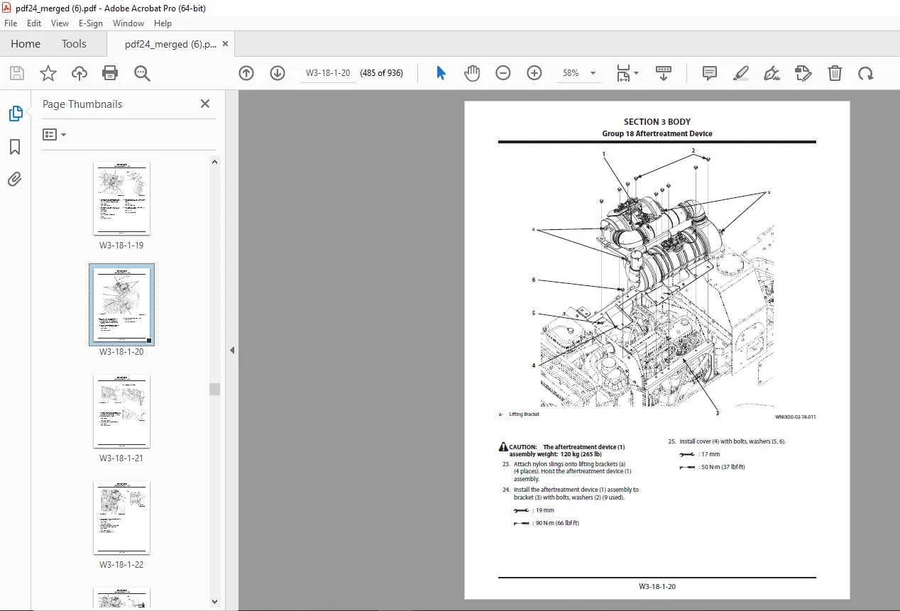
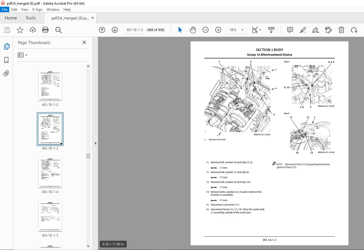
Group 18 Aftertreatment Device0
Removal and Installation of Aftertreatment Device0
Group 19 DEF Tank0
Removal and Installation of DEF Tank0
Group 20 Coolant Control Valve0
Removal and Installation of Coolant Control Valve0
Group 21 DEF Supply Module0
Removal and Installation of DEF Supply Module0
Group 22 Exterior Components0
Removal and Installation of Exterior Components0
SECTION 4 TRAVEL SYSTEM CONTENTS583
SECTION 4 TRAVEL SYSTEM585
Group 1 Tire585
Removal and Installation of Front Tire585
Removal and Installation of Rear Tire591
Group 2 Drive Unit597
Removal and Installation of Drive Unit597
Disassembly and Assembly of Drive Unit605
Removal and Installation of Torque Converter611
Disassembly and Assembly of Transmission617
Disassembly and Assembly of Transmission Control Valve667
Removal and installation of parking brake (Replace the brake friction pad)681
Group 3 Axle691
Removal and Installation of Front Axle691
Removal and Installation of Rear Axle701
Disassembly of Axle717
Assembly of Axle734
Group 4 Propeller Shaft761
Removal and Installation of Propeller Shaft761
Group 5 Brake Valve773
Removal and Installation of Brake Valve773
Disassembly of Brake Valve780
Disassembly of Brake Valve780
Assembly of Brake Valve782
Assembly of Brake Valve782
Group 6 Steering Device785
Removal and Installation of Steering Pilot Valve785
Disassembly of Steering Pilot Valve791
Assembly of Steering Pilot Valve794
Removal and Installation of Steering Valve (Without Secondary Steering)799
Removal and Installation of Steering Valve (With Secondary Steering)807
Disassembly of Steering Valve815
Assembly of Steering Valve818
Disassembly of Secondary Steering Check Block821
Assembly of Secondary Steering Check Block823
Removal and Installation of Steering Cylinder825
Disassembly of Steering Cylinder847
Assembly of Steering Cylinder851
Removal and Installation of Left Stop Valve857
Removal and Installation of Right Stop Valve863
Disassembly of Stop Valve869
Assembly of Stop Valve870
Group 7 Secondary Steering Device871
Removal and Installation of Secondary Steering Pump871
SECTION 5 FRONT ATTACHMENT CONTENTS881
SECTION 5 FRONT ATTACHMENT883
Group 1 Front Attachment883
Removal and Installation of Front Attachment883
Removal and Installation of Bell Crank (Lever)893
Removal and Installation of Bucket901
Removal and Installation of Bushing905
Group 2 Cylinder909
Removal and Installation of Lift Arm Cylinder909
Removal and Installation of Bucket Cylinder917
Disassembly of Lift Arm Cylinder and Bucket Cylinder929
Assembly of Lift Arm Cylinder and Bucket Cylinder933
SECTION 1 GENERAL0
Group 1 Precautions for Disassembling and Assembling0
Precautions for Disassembling and Assembling0
Group 2 Tightening0
Tightening Bolts and Nuts0
Piping Joint0
Group 3 Painting0
Group 4 Bleeding Air0
Bleed Air from the Hydraulic System0
Bleed Air from the Fuel System0
Bleeding Air from Brake (Axle)0
Group 5 Preparation0
Preparations for Inspection and Maintenance 0
Releasing Pressure from Front Attachment Hydraulic Circuit0
Releasing Pressure from Ride Control Accumulator0
Releasing Pressure from Parking Brake Accumulator0
Releasing Pressure from Hydraulic Oil Tank0
Releasing Pressure from Reserve Tank0
SECTION 2 MAINTENANCE STANDARD CONTENTS0
SECTION 2 MAINTENANCE STANDARD0
Group 1 Body0
Center Hinge0
Group 2 Front Attachment0
Pin and Bushing0
Standard Dimensions for Lift Arm and Bucket0
Cylinder0
SECTION 3 BODY CONTENTS0
SECTION 3 BODY0
Group 1 Cab0
Removal and Installation of Cab0
Group 2 Counterweight0
Removal and Installation of Counterweight0
Group 3 Center Hinge0
Removal and Installation of Center Hinge0
Group 4 Engine0
Removal and Installation of Engine0
Group 5 Radiator Assembly0
Removal and Installation of Radiator Assembly0
Group 6 Hydraulic Oil Tank0
Removal and Installation of Hydraulic Oil Tank0
Group 7 Fuel Tank0
Removal and Installation of Fuel Tank0
Group 8 Pump Device0
Removal and Installation of Pump Device0
Disassembly of Pump Device0
Assembly of Pump Device0
Disassembly of Main Pump0
Assembly of Main Pump0
Disassembly of Regulator0
Assembly of Regulator0
Disassembly of Priority Valve0
Assembly of Priority Valve0
Structure of Pilot Pump0
Group 9 Multiple Control Valve0
Removal and Installation of Multiple Control Valve0
Disassembly of Multiple Control Valve0
Disassembly of Multiple Control Valve0
Assembly of Multiple Control Valve0
Assembly of Multiple Control Valve0
Group 10 Pilot Valve0
Removal and Installation of Pilot Valve0
Removal and Installation of Pilot Valve (Two Lever Type)0
Disassembly of Pilot Valve0
Assembly of Pilot Valve0
Disassembly of Pilot Valve (Two Lever Type)0
Assembly of Pilot Valve (Two Lever Type)0
Group 11 Brake Charge Valve0
Removal and Installation of Brake Charge Valve (Unloader Valve)0
Structure of Brake Charge Valve (Unloader Valve)0
Removal and Installation of Brake Accumulator0
Group 12 Manifold Valve0
Removal and Installation of Manifold Valve0
Disassembly of Manifold Valve0
Assembly of Manifold Valve0
Group 13 Solenoid Valve0
Removal and Installation of 2-Spool Solenoid Valve Unit0
Structure of 2-Spool Solenoid Valve Unit0
Removal and Installation of Parking Brake Solenoid Valve Unit0
Structure of Parking Brake Solenoid Valve Unit0
Structure of Parking Brake Solenoid Valve0
Group 14 Flow Regulator Valve0
Removal and Installation of Flow Regulator Valve0
Structure of Flow Regulator Valve0
Group 15 Cooling Fan System0
Removal and Installation of Fan Valve0
Structure of Fan Valve0
Removal and Installation of Fan Motor0
Structure of Fan Motor0
Removal and Installation of Fan Pump0
Disassembly of Fan Pump0
Assembly of Fan Pump0
Group 16 Ride Control Accumulator0
Removal and Installation of Ride Control Accumulator0
Group 17 Battery Disconnect Switch0
Removal and Installation of Battery Disconnect Switch0
Group 18 Aftertreatment Device0
Removal and Installation of Aftertreatment Device0
Group 19 DEF Tank0
Removal and Installation of DEF Tank0
Group 20 Coolant Control Valve0
Removal and Installation of Coolant Control Valve0
Group 21 DEF Supply Module0
Removal and Installation of DEF Supply Module0
Group 22 Exterior Components0
Removal and Installation of Exterior Components0
SECTION 4 TRAVEL SYSTEM CONTENTS583
SECTION 4 TRAVEL SYSTEM585
Group 1 Tire585
Removal and Installation of Front Tire585
Removal and Installation of Rear Tire591
Group 2 Drive Unit597
Removal and Installation of Drive Unit597
Disassembly and Assembly of Drive Unit605
Removal and Installation of Torque Converter611
Disassembly and Assembly of Transmission617
Disassembly and Assembly of Transmission Control Valve667
Removal and installation of parking brake (Replace the brake friction pad)681
Group 3 Axle691
Removal and Installation of Front Axle691
Removal and Installation of Rear Axle701
Disassembly of Axle717
Assembly of Axle734
Group 4 Propeller Shaft761
Removal and Installation of Propeller Shaft761
Group 5 Brake Valve773
Removal and Installation of Brake Valve773
Disassembly of Brake Valve780
Disassembly of Brake Valve780
Assembly of Brake Valve782
Assembly of Brake Valve782
Group 6 Steering Device785
Removal and Installation of Steering Pilot Valve785
Disassembly of Steering Pilot Valve791
Assembly of Steering Pilot Valve794
Removal and Installation of Steering Valve (Without Secondary Steering)799
Removal and Installation of Steering Valve (With Secondary Steering)807
Disassembly of Steering Valve815
Assembly of Steering Valve818
Disassembly of Secondary Steering Check Block821
Assembly of Secondary Steering Check Block823
Removal and Installation of Steering Cylinder825
Disassembly of Steering Cylinder847
Assembly of Steering Cylinder851
Removal and Installation of Left Stop Valve857
Removal and Installation of Right Stop Valve863
Disassembly of Stop Valve869
Assembly of Stop Valve870
Group 7 Secondary Steering Device871
Removal and Installation of Secondary Steering Pump871
SECTION 5 FRONT ATTACHMENT CONTENTS881
SECTION 5 FRONT ATTACHMENT883
Group 1 Front Attachment883
Removal and Installation of Front Attachment883
Removal and Installation of Bell Crank (Lever)893
Removal and Installation of Bucket901
Removal and Installation of Bushing905
Group 2 Cylinder909
Removal and Installation of Lift Arm Cylinder909
Removal and Installation of Bucket Cylinder917
Disassembly of Lift Arm Cylinder and Bucket Cylinder929
Assembly of Lift Arm Cylinder and Bucket Cylinder933
DESCRIPTION:
KCM 80Z7B Wheel Loader(Disassembly & Reassembly) CUMMINS QSB6.7 ENGINE Shop Manual – PDF DOWNLOAD
SN 80C8-5001 and up
PN 93209-00720
Precautions for Disassembling and Assembling:
Precautions for Disassembling:
- Clean the Machine Thoroughly wash the machine before bringing it into the shop. Bringing a dirty machine into the shop may cause machine components to be contaminated during disassembling / assembling, resulting in damage to machine components as well as decreased efficiency in service work.
- Inspect the Machine Be sure to thoroughly understand all disassembling / assembling procedures beforehand to help avoid incorrect disassembling of components as well as personal injury. Check and record the items listed below to prevent problems from occurring in the future.
- The machine model, machine serial number, and hour meter reading.
- Reason for disassembly (symptoms, failed parts, and causes).
- Clogging of filters and oil, water, or air leaks, if any. Capacities and condition of lubricants.
- Loose or damaged parts.
- Prepare and Clean Tools and Disassembly Area Prepare the necessary tools to be used and the area for disassembling work. Precautions for Disassembling and Assembling
- Precautions for Disassembling
- Cap the open ends in case the hoses and pipes have been disconnected. In addition, attach identification tags onto the connectors, hoses, and pipes for assembling. Before disassembling, clean the exterior of the components and place on a workbench.
- Drain hydraulic oil and gear oil from the hydraulic components and reduction gear.
- Be sure to provide appropriate containers for draining fluids. Use matching marks for easier reassembling if necessary.
- Be sure to use the specified special tools when instructed.
Maintenance Standard Terminology “Standard:
1. Dimension for parts on a new machine.
2. Dimension of new components or assemblies adjusted to specification. Allowable errors will be indicated if necessary
G.B 04/02/25