KCM 95ZV WHEEL LOADER SHOP MANUAL 93215-00226 – PDF DOWNLOAD
$31.95
KCM 95ZV WHEEL LOADER SHOP MANUAL 93215-00226 – PDF DOWNLOAD
General Information
Standard Measurement Values for
Performance Check
Function & Structure
Check & Adjustment
Powered by CUMMINS QSX15 ENGINE
Serial No. 97C4-0101 and up
97C4-9001 and up
Description
KCM 95ZV WHEEL LOADER SHOP MANUAL 93215-00226 – PDF DOWNLOAD
FILE DETAILS:
KCM 95ZV WHEEL LOADER SHOP MANUAL 93215-00226 – PDF DOWNLOAD
Language :English
Pages :652
Downloadable : Yes
File Type : PDF
IMAGES PREVIEW OF THE MANUAL:
DESCRIPTION:
KCM 95ZV WHEEL LOADER SHOP MANUAL 93215-00226 – PDF DOWNLOAD
General Information
Standard Measurement Values for
Performance Check
Function & Structure
Check & Adjustment
Powered by CUMMINS QSX15 ENGINE
Serial No. 97C4-0101 and up
97C4-9001 and up
Foreword
To ensure good machine performance, reduce failures or problems, and prolong the service life of each component,
it is necessary to operate the machine as is directed in the Operator and Maintenance Manual.
To effectively diagnose and repair the machine, it is important to follow the guidelines laid out in this Shop Manual.
General Information
Function and structure
For the engine, refer to the engine Shop Manual provided by the engine manufacturer.
The purpose of this manual is to provide information on the product and the correct maintenance and repair methods.
Please read this manual to ensure correct troubleshooting and good repair service.
This manual will be periodically reviewed and revised for more satisfactory content. If you have any opinion or
requests, please inform us.
TABLE OF CONTENTS:
KCM 95ZV WHEEL LOADER SHOP MANUAL 93215-00226 – PDF DOWNLOAD
General Information
Standard Measurement Values for
Performance Check
Function & Structure
Check & Adjustment
Powered by CUMMINS QSX15 ENGINE
Serial No. 97C4-0101 and up
97C4-9001 and up
Foreword 2
MACHINE SPECIFICATION 2
Safety Symbols 3
CONTENTS 4
00 General Information 18
How to Use Manual 19
Safety precautions 19
Symbols 20
Outline 21
Layout of main components 21
Recommended lubricants 25
Coolant 27
Coolant specification 27
Recommended mixture of antifreeze 27
Lubrication chart 28
Weight of main components 29
Bolt tightening torque 30
Hexagon bolt 30
Flanged hexagon bolt 33
Hose band tightening torque 34
Liquid gasket and screw lock agent 35
Cautions regarding parts removal 35
Cautions regarding reassembly 35
Screw lock agent application procedure 36
How to wind a seal tape 36
Cautions regarding welding repair service 37
Cautions 37
03 Measurement for Performance Check 40
Cautions on Safety 41
Standard Measurement Values for Performance Check 42
12 Function & Structure Chassis Group 48
Front Chassis 49
Loading linkage 49
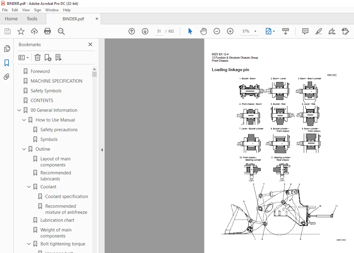
Loading linkage pin 51
Rear Chassis 52
Fuel tank (S/N 0101~0262, 9001~9064) 52
Fuel tank (S/N 0263~, 9065~) 53
Floor board mount 54
Floor board 54
Viscous mount 54
Center Pin 55
Upper center pin 55
Lower center pin 55
Dust seal 56
13 Check & Adjustment Chassis Group 58
Linkage Pin 59
Liner 59
Adjustment 60
Bucket hinge pin section 61
How to assemble 61
Center Pin 62
Adjusting shim 62
Grease nipple installation direction 62
Installing bearing outer ring 63
22 Function & Structure Power Group 64
Power Line 65
Engine / Transmission 66
Engine / transmission mount 66
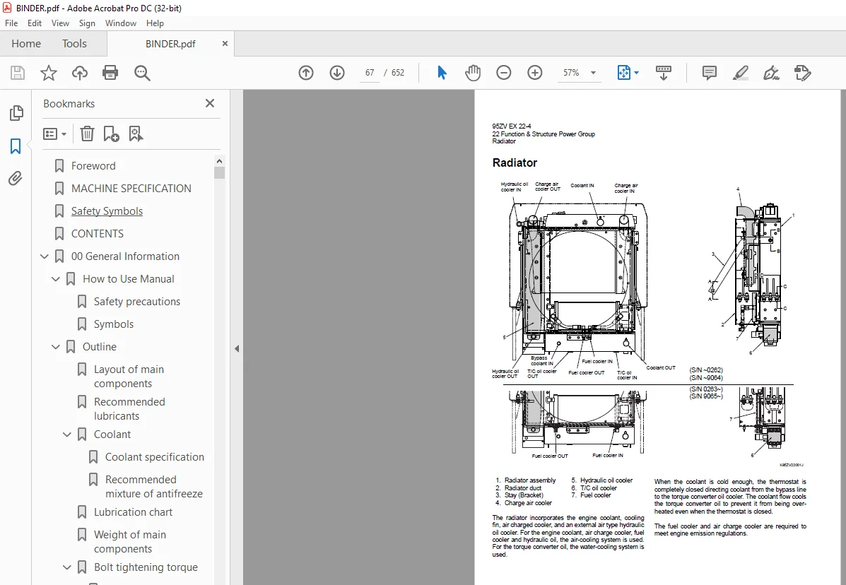
Radiator 67
Radiator mount 68
Propeller Shaft 69
Second propeller shaft assembly 70
Front differential – Transmission 70
Third propeller shaft assembly 71
Transmission – Rear differential 71
Axle Assembly 72
Axle Support 75
Differential Gear 81
Function of T P D 85
Difference in gear shapes 85
Contact between pinion and side gear 85
Operation of T P D 86
23 Check & Adjustment Power Group 88
Engine 89
Measuring engine speed 89
Measuring engine oil pressure 89
Propeller Shaft 90
Propeller shaft phase 90
Second propeller shaft alignment 90
Propeller shaft tightening torque 91
Axle 92
Axle nut tightening procedure 92
Planetary gear oil drain and refill 93
Differential gear adjustment procedure 94
Preload adjustment 95
Bearing installation 96
Oil seal installation 96
Adjusting tooth contact 97
32 Function & Structure Torque Converter and Transmission Group 100
Torque Converter 101
Torque converter structure 101
Power flow path 101
Torque multiplication 101
Torque Converter Gear Pump 102
Gear pump specifications 102
Gear pump specifications 103
Clutch combination 104
Planetary gear 104
Shift lever position 104
QUAD switch operation 104
Gear train and number of teeth 105
Clutch specifications 105
Friction plate 106
Steel plate 107
Clutch Pack 108
Power Flow Path in the Transmission 109
Forward 1st speed flow path 109
Forward 2nd speed flow path 110
Forward 3rd speed flow path 110
Forward 4th speed flow path 111
Reverse 1st speed flow path 112
Reverse 2nd speed flow path 112
Reverse 3rd speed flow path 113
Hydraulic System Diagram 114
Hydraulic Circuit Diagram 115
Oil Flow 116
Oil flow in the torque converter line 116
Oil flow to the clutch 116
T/C and T/M Oil Circulation 117
Modulator Valve Unit 118
Interior schematic (example) 120
Modulation Mechanism 121
Modulator valve function 121
Modulator valve 1 121
Modulator valve 2 122
Pressure difference sensor (S/N ~0556) 122
Clutch oil pressure control at the time of engine starting 122
Modulator valve operation 123
Clutch Solenoid Valve 124
For high/reverse and speed clutches 126
33 Check & Adjustment Torque Converter and Transmission Group 128
Clutch Oil Pressure and Time Lag 129
Measuring clutch oil pressure 129
Clutch oil pressure measurement procedure 130
Possible causes for low clutch oil pressure 130
Measuring clutch time lag 131
Time lag measurement procedure 131
Possible causes for clutch time lag 131
42 Function & Structure Hydraulic Group 132
Flushing Hydraulic Circuit 133
Purpose of flushing 133
Cautions on Hydraulic Parts Replacement 134
Hydraulic Circuit Symbols 135
Hydraulic lines 135
Pumps & motors 135
Cylinders 135
Operation methods 136
Pressure control valve 136
Flow control valve 136
Directional control valve 137
Check valve 137
Miscellaneous hydraulic symbols 138
Hydraulic System Operation 139
Hydraulic system operation outline 139
Loading system 139
Steering system 140
Fan motor system 140
Vibration damper system (OPT) 140
Layout of Hydraulic Units 141
Hydraulic Tank 142
Hydraulic tank specifications 142
Hydraulic oil level check 142
Hydraulic tank (S/N 0101~0450, 9001~) 143
Hydraulic tank breather valve (tank cap) (S/N 0101~0450, 9001~) 144
Hydraulic tank (S/N 0451~) 146
Hydraulic tank breather valve (tank cap) (S/N 0451~) 147
Hydraulic Pump 148
Loading and pilot and brake pump 150
Pump specifications 150
Steering pump (S/N 0101~0258, 9001~9065) 151
Pump specifications 151
Steering pump (S/N 0259~0398, 9066~) 152
Pump specifications 152
Steering pump (S/N 0399~0465) 154
Pump specifications 154
Steering pump (S/N 0466~) 156
Pump specifications 156
Hydraulic pump principle 157
Hydraulic pump wear plate 158
Hydraulic pump bushing lubrication 158
Hydraulic Cylinder 159
Boom cylinder 159
Bucket cylinder 160
Steering cylinder 161
Hydraulic cylinder specifications 162
Loading System 163
Reducing Valve (for Pilot Pressure) 164
Pilot Valve (S/N 0101~0290, 9001~9080) 165
Pilot valve operation 167
Pilot valve detent magnet solenoid 169
Detent adjustment procedure 169
Pilot valve (S/N 0291~0408, 9081~) 170
Pilot valve operation 172
Pre-detent and detent magnet solenoid 174
Pilot valve (S/N 0409~0410) 175
Pilot valve function 177
Pilot valve operation (modulated position) 177
Pre-detent and detent magnet solenoid 179
Pilot valve (S/N 0411~) 180
Pilot valve function 182
Pilot valve operation (modulated position) 182
Pre-detent and detent magnet solenoid 184
Multiple Control Valve (KML35A/2T003B) 185
Multiple control valve specifications 186
Multiple control valve main relief valve 187
Main relief valve operation 187
Adjusting set pressure 188
Multiple control valve overload relief valve 189
Overload relief valve operation 189
Make-up valve operation 190
Adjusting set pressure 190
Multiple control valve make-up valve 191
Make-up valve operation 191
Multiple control valve bucket spool 192
Bucket spool operation 192
Multiple control valve boom spool 194
Boom spool operation 194
Adapter (Orifice) 197
Vibration Damper (OPT) 198
Vibration damper hydraulic circuit 198
Vibration damper function 198
Vibration damper operation 199
Reducing valve 202
Check valve 202
Solenoid valve 203
Shuttle valve 205
Solenoid valve 205
Check valve 206
Vibration damper hydraulic line 208
Steering System 209
Orbitrol® 210
Orbitrol® specification 210
Orbitrol® structure 211
Valve part 211
Rotor part 211
Orbitrol® operation 212
Neutral 212
Turn 213
Orbitrol® feed-back mechanism operation 214
Steering speed and flow rate control 215
Hydraulic pump oil amount and steering force 215
Orbit rotor operation principle 216
Steering Valve (KVS32-A4 0) 217
Steering valve operation 220
Neutral position 220
Left turn position 221
Steering plunger variable throttle 222
Steering valve flow control plunger 223
Steering valve main relief valve 224
When the pressure is at the preset value or less 224
When the pressure exceeds the preset value 225
Steering valve overload relief valve 226
Overload relief valve operation 227
Make-up valve operation 227
Steering pilot circuit and its operation 228
Flow amplifier notch and pilot orifice 229
Stop Valve 230
Stop valve function 232
Stop valve operation 233
Reducing Valve (for Orbitrol®) 234
Steering Line Filter 235
Fan Motor System 237
Fan Motor Line (S/N 0101~0230) 239
Fan motor (GM30C) (S/N 0101~0230) 241
Valve assembly (for fan motor) 242
Relief valve (two-step relief) 243
Relief valve (two-step relief) operation 244
Make-up valve operation 245
Solenoid valve (for fan speed control) 246
Solenoid valve (for fan speed control) operation 246
Fan Motor Line (S/N 0231~) 247
Fan motor (GM30C) (S/N 0231~0313) 250
Fan motor (GM30W) (S/N 0314~0398) 251
Fan motor (FM30) (S/N 0399~0466) 253
Fan motor (S/N 0467~) 255
Fan motor function and the operation principle 257
Thermo sensing valve 258
Thermo sensing valve operation 259
Fan motor relief valve assembly 260
Fan motor relief valve 261
Fan motor check valve (make-up valve) 261
Fan Motor Line (S/N 9001~9010) 262
Fan motor (GM30C) (S/N 9001~9010) 264
Valve assembly (for fan motor) 265
Relief valve (two-step relief) 266
Relief valve (two-step relief) operation 267
Make-up valve operation 268
Solenoid valve (for fan speed control) 269
Solenoid valve (for fan speed control) operation 269
Fan Motor Line (S/N 9011~) 270
Fan motor (GM30C) (S/N 9011~9065) 273
Fan motor specifications 273
Fan motor (GM30W) (S/N 9066~) 274
Thermo sensing valve 276
Thermo sensing valve operation 277
Fan motor relief valve assembly 278
Fan motor relief valve 279
Fan motor check valve (make-up valve) 279
Emergency Steering (for Europe) 280
Emergency steering operation condition 280
Emergency steering line oil flow 280
Emergency steering hydraulic diagram 281
Machine speed signal 282
Emergency steering motor and pump 282
43 Check & Adjustment Hydraulic Group 284
Loading/Steering Circuit Relief Valve 285
Loading circuit relief valve setting pressures 285
Measuring loading circuit main relief pressure 287
Measuring loading circuit overload relief pressure 288
Measuring pilot circuit relief pressure 289
Steering circuit relief valve setting pressures 290
Measuring steering circuit main relief pressure 292
Measuring steering circuit overload relief pressure 293
Measuring pilot circuit relief pressure (reducing pressure) (S/N 0107~, 9004~) 294
Hydraulic Cylinder 295
Cylinder natural drift 295
Cylinder natural drift measurement procedure 295
Stop Valve 297
Stop valve adjustment procedure 297
Fan Revolution (S/N 0101~) 298
Fan maximum revolution measurement (S/N 0101~0230) 298
Fan maximum revolution measurement (S/N 0231~) 300
Fan Revolution (S/N 9001~) 302
Fan maximum revolution measurement (S/N 9001~9010) 302
Fan maximum revolution measurement (S/N 9011~) 304
52 Function & Structure Brake Group 306
Brake System Outline 307
Service brake 307
Parking brake 307
Auto brake 307
Adjustment of axle internal pressure 307
Brake Units Layout 308
Unloader Valve 309
Unloader valve operation 311
Valve Unit 312
Reducing Valve 313
Brake Accumulator Line 314
Accumulator 315
In-line filter 316
Brake circuit check valve 317
Brake Valve 318
Brake main valve (left pedal) 318
Brake pilot valve (right pedal) 320
Brake valve performance chart 322
Brake valve outline 325
Main valve (tandem type) operation 325
Pilot valve operation 326
Stop Lamp Pressure Switch 327
Pressure switch (for stop lamp) 327
Pressure switch (for declutch) 328
Service Brake 329
Service brake operation 329
Service brake friction plate 330
Service brake steel plate 330
Service brake piston 331
Service brake pedal stroke adjusting mechanism (S/N 0101~0311, 9001~9095) 333
Tolerance ring 334
Brake circuit air bleeding procedure 335
Bleeding air from the brake valves 336
Bleeding air from brake pipes and axle housing hubs 336
Parking Brake 337
Parking brake operation chart 337
Parking Brake (Rear) 338
Rear parking brake operation 338
Parking brake solenoid valve (rear) 339
Parking solenoid valve operation (rear) 339
Parking brake manual release procedure (rear) 340
Parking brake spring chamber 342
Parking Brake (Front) (for Europe only) 343
Front parking brake operation 343
Parking brake solenoid valve (front) 344
Parking solenoid valve operation (front) 344
Front parking brake auto adjuster mechanism 345
Parking brake line air bleeding procedure (front parking) 346
Parking brake manual release procedure (front) 347
Auto Brake 348
Auto brake circuit 348
Auto brake operation set value 348
Solenoid valve (for autobrake circuit) 349
Shuttle valve 350
53 Check & Adjustment Brake Group 352
Brake Circuit Oil Pressure 353
Unloader valve setting pressure 353
Measuring unloader valve setting pressure 354
Adjusting unloader valve setting pressure 354
Accumulator circuit pressure 355
Measuring reducing valve setting pressure 355
Adjusting reducing valve setting pressure 356
Brake valve oil pressure 357
Measuring brake valve oil pressure 357
Brake valve performance 358
Service Brake 359
Service brake performance check 359
Method 1 359
Method 2 359
Service brake friction plate wear measurement 360
Cautions when installing brake discs (S/N 0101~0311, 9001~9095 only) 362
Parking Brake 363
Parking brake performance check 363
Method 1 363
Method 2 363
Parking brake clearance adjustment 365
Brake lining abrasion check 366
62 Function & Structure Electrical Group 368
How to Use Electrical Wiring Diagram 369
Utilisation des schémas des câblages électriques (FRANÇAIS) 370
Verwendung des elektrischen Schaltplans (DEUTSCH) 371
Modalità di utilizzo dello schema dei collegamenti elettrici (ITALIANO) 372
Cómo utilizar un Diagrama de Alambrado Eléctrico (ESPAÑOL) 373
Como Utilizar o Diagrama de Ligações Eléctricas (PORTUGUÊS) 374
Electrical Cable Color Codes 375
Electrical Circuit Symbols 376
Sensor Mount 377
Fuse 378
Fuse box location 378
Fuse box 379
Fusible link 380
Engine Start Circuit 382
Engine start circuit diagram (S/N 0101~0358, 9001~) 382
Neutral starter 382
Shift lever neutral (N) position 382
Shift lever forward/reverse (F/R) position 382
Engine start circuit diagram (S/N 0359~) 383
Neutral starter 385
Shift lever neutral (N) position 385
Shift lever forward/reverse (F/R) position 385
Starter switch 386
Battery relay 387
Battery relay operation 387
Alternator I terminal wire 387
Diode unit 388
Neutral relay 388
Magnet switch 389
Voltage relay 390
Power Generating/Charging Circuit 391
Alternator 391
ECM (Engine Controller) 392
Function of ECM 392
Connection diagram 392
Monitor lamp test 393
Failure diagnosis 394
Engine diagnostic switch (option) 394
Engine diagnostic switch (option) 396
Failure diagnostic chart 397
Increment decrement switch (option) 398
Quantum fault code information 399
Accelerator pedal 406
Accelerator pedal installation 407
Accelerator pedal 408
Accelerator pedal installation 409
Transmission Control Circuit and Monitor Circuit (S/N 0101~0358, 9001~) 410
Controller 410
LED inspection windows 411
Controller connection diagram 412
Controller function 413
Forward/reverse (F/R) shifting and speed change 413
Automatic shift 415
Machine speed sensor 417
Switching from automatic to manual 418
QUAD (downshift) switch operation 418
Modulation at clutch switching 419
Transmission cut off (Declutch) 422
Pressure switch for inching (declutch) 423
Back-up alarm 424
Parking brake 425
Auto brake 428
Transmission controller failure warning 431
Emergency steering function (for Europe spec only) 432
Transmission Control Circuit and Monitor Circuit (S/N 0359~) 433
Machine control unit (MCU) 433
Connector 434
Machine control unit (MCU) connection diagram (S/N 0359~0476) 435
Machine control unit (MCU) connection diagram (S/N 0477~) 436
Machine control unit (MCU) failure warning 437
Monitoring System (S/N 0101~0358, 9001~) 438
Monitor controller 438
Monitor controller connection diagram 439
Monitor controller function 440
Items to be monitored and operation condition 440
Operation monitor lamps 441
Instrument Panel and Switch 443
Instrument panel 443
Instrument panel rear surface 445
Gauge circuit 447
Temperature sensor 448
Tachometer circuit 449
Tachometer 449
Fuel gauge circuit 450
Electrical Detent Circuit 452
Bucket leveler 452
Boom kick-out (option) 453
Float 453
Proximity switch 453
Detent solenoid 454
Diode 455
Diode check method 456
Caution for diode check method 456
Continuity check mode 456
Diode check mode 456
Resistance check mode 457
Surge voltage and surge suppression diodes 458
Diagnostic System (S/N 0101~0358, 9001~) 459
Diagnostic system flow 459
Diagnostic system flow 459
Failure code (T/M controller) 460
Diagnostic (T/M controller) failure code detection condition 461
Fault diagnostic result storage condition 462
Monitor controller 463
Diagnostic system flow 463
Alarm monitor actuation and data storage 464
Diagnostic failure history indication and deletion 466
Failure history indication 466
Failure history deletion 467
Diagnostic switch 468
MODM (S/N 97C4-0359~) 469
MODM function 469
Monitor Changeover 469
Changing display from one function to next 469
MODM: Input/output monitor – Input/output signal correspondence table 476
63 Check & Adjustment Electrical Group 480
Cautions Regarding Electric Circuit Check 481
Disconnecting or reinstalling connector 481
How to attach the probes of the circuit tester 483
Electrical Transmission Control System Troubleshooting Flowchart (S/N 0101~0358, 9001~) 484
Standard troubleshooting flowchart 484
Transmission Controller Abnormal Operation Judgment (S/N 0101~0358, 9001~) 485
Transmission controller check 485
When the “controller failure” monitor lamp lights: 485
When the output units (solenoid valve, etc ) do not operate properly: 485
If the input units or circuit are not defective 486
Transmission controller LED indicator 487
Electrical Circuit Check (S/N 0101~0358, 9001~) 489
Shift lever input electrical circuit check 489
Inching (declutch) input electrical circuit check 491
QUAD switch input electrical circuit check 493
Machine speed sensor input electrical circuit check 494
Clutch solenoid valve output electrical circuit check 495
Modulator valve output electrical circuit check 497
Check output circuit wiring 498
Neutral relay electrical circuit check 499
Parking brake electrical circuit check 500
Solenoid valve on the front side 502
Auto brake electrical circuit check 503
Gauge circuit electrical circuit check 505
Fuel level gauge electrical circuit check 507
Shift Lever 509
Operation force measurement 509
Changeover between forward and reverse 509
Transmission gear changeover 509
72 Function & Structure Operator Station Group 510
Cabin 511
Glass 512
1 Part number 32011-21690 513
2 Part number 32011-21700 513
3 Part number 32011-21500 514
Wiper mount 515
Front wiper 515
Rear wiper 515
Wiper motor 516
Operator Seat 518
Steering and Transmission Shift Lever 519
Tilt case 520
Column shaft 521
Shift lever 521
Air Conditioner 522
Air conditioner components 522
Air conditioner specifications (system performance) 522
Air conditioner structure 523
Cooling unit 523
Heater and accessories 525
Air distributor (hood & defroster selection box) 525
Air compressor (with magnetic clutch) 526
Condenser unit 526
Control unit 527
Cooling mechanism 528
Principle of cooling 528
Refrigerant 528
Refrigerant characteristics 529
Cooling circuit 530
Electrical circuit 531
Control schematic drawing 531
Air conditioner functions of components 532
Control panel 532
Air conditioner unit 539
Compressor and magnetic clutch 548
Condenser unit 551
Receiver dryer 553
Sight glass 555
Pressure switches 555
Pressure relief valve 556
Relay A 557
Relay B 557
Refrigerant hose 558
Charge of refrigerant 559
Work procedure 560
Refrigerant charging tools 561
Refrigerant charging procedure 564
Troubleshooting using the gauge manifold 569
Air conditioner troubleshooting 574
Fault diagnosis procedure 574
73 Check & Adjustment Operator Station Group 582
Air Conditioner 583
Adjustment of lubricating oil quantity when components of air conditioner are replaced 583
When the compressor is replaced 584
When the evaporator is replaced 585
When the condenser is replaced 585
Adjustment of air gap (between hub and rotor) in compressor magnetic clutch 586
Parts to be replaced periodically 587
Air filters 587
Receiver dryer 587
INDEX 588
Maintenance Log 595
Notes 599
92 Cross-Section Drawing & Diagrams 603
Axle Assembly 604
Torque Converter and Transmission 605
Loading/Steering Hydraulic Line (S/N 0101~0230) 606
Loading/Steering Hydraulic Line (S/N 0231~) 607
Loading/Steering Hydraulic Circuit (S/N 9001~9010) 608
Loading/Steering Hydraulic Circuit (S/N 9011~) 609
Brake Circuit 610
Electrical Wiring Diagram (1/2) (S/N 0101~0358) 611
Electrical Wiring Diagram (2/2) (S/N 0101~0358) 612
Electrical Wiring Diagram (1/3) (S/N 0359~0476) 613
Electrical Wiring Diagram (2/3) (S/N 0359~0476) 614
Electrical Wiring Diagram (3/3) (S/N 0359~0476) 615
Electrical Wiring Diagram (1/3) (S/N 0477~0560) 616
Electrical Wiring Diagram (2/3) (S/N 0477~0560) 617
Electrical Wiring Diagram (3/3) (S/N 0477~0560) 618
Electrical Wiring Diagram (1/3) (S/N 0561~) 619
Electrical Wiring Diagram (2/3) (S/N 0561~) 620
Electrical Wiring Diagram (3/3) (S/N 0561~) 621
Electrical Wiring Diagram (1/2) (S/N 9001~9080) 622
Electrical Wiring Diagram (2/2) (S/N 9001~9080) 623
Electrical Wiring Diagram (1/2) (S/N 9081~) 624
Electrical Wiring Diagram (2/2) (S/N 9081~) 625
Electrical wiring diagram abbreviation chart (S/N 0101~0358, 9001~) 626
Electrical wiring diagram abbreviation chart (S/N 0359~0476) 627
Electrical wiring diagram abbreviation chart (S/N 0477~) 628
Electrical Wiring Diagram (CAB) 629
Electrical Connection Diagram (S/N 0101~0358) 631
Electrical Connection Diagram (S/N 0359~0476) 632
Electrical Connection Diagram (1/2) (S/N 0477~0560) 633
Electrical Connection Diagram (2/2) (S/N 0477~0560) 634
Electrical Connection Diagram (1/2) (S/N 0561~) 635
Electrical Connection Diagram (2/2) (S/N 0561~) 636
Electrical Connection Diagram (S/N 9001~) 637
Electrical Circuit Diagram (Cabin Air Conditioner) 638
Electrical Wiring Diagram (Cabin Air Conditioner) 639
Equipment Operation Table (Cabin Air Conditioner) 640
Electrical Equipment Layout 641
S.M 7/2/2025