Keithley 6517A Electrometer Service Manual Calibration Repair Guide PDF
Original price was: $95.00.$18.95Current price is: $18.95.
Complete factory service manual for Keithley 6517/6517A Electrometer with detailed calibration procedures, performance verification, troubleshooting guides, and repair information. Includes IEEE-488 bus calibration commands, offset voltage calibration, DC volts/amps verification procedures, voltage source calibration, and complete parts lists. Essential technical documentation for biomedical equipment technicians, calibration labs, and electronics service professionals maintaining precision electrometry instruments.
Description
Keithley 6517A Electrometer Service Manual Calibration Repair Guide PDF DOWNLOAD
DESCRIPTION
Keithley 6517A Electrometer Complete Service & Calibration Manual
This comprehensive Keithley 6517 service manual provides complete technical documentation for servicing, calibrating, and repairing the Model 6517/6517A Electrometer. This precision measurement instrument is used in research laboratories, calibration facilities, and biomedical equipment maintenance for ultra-sensitive electrical measurements.
📋 FILE DETAILS
| Specification | Details |
|---|---|
| Manual Name | Keithley Model 6517A Electrometer Service Manual |
| Models Covered | 6517, 6517A |
| Publication Date | April 1999 (Revision B) |
| Document Number | 6517A-902-01 Rev. B |
| Total Pages | 119 pages |
| PDF Quality | Excellent – Original factory scanned document |
| File Format | PDF (Searchable text) |
| File Size | 2.8 MB |
📖 COMPLETE TABLE OF CONTENTS
SECTION 1: PERFORMANCE VERIFICATION (Pages 1-1 to 1-17)
- Environmental Conditions & Warm-up Requirements
- Recommended Test Equipment Lists
- Meter performance verification equipment
- Voltage source verification equipment
- Temperature verification equipment
- Humidity verification equipment
- Verification Limits & Default Conditions
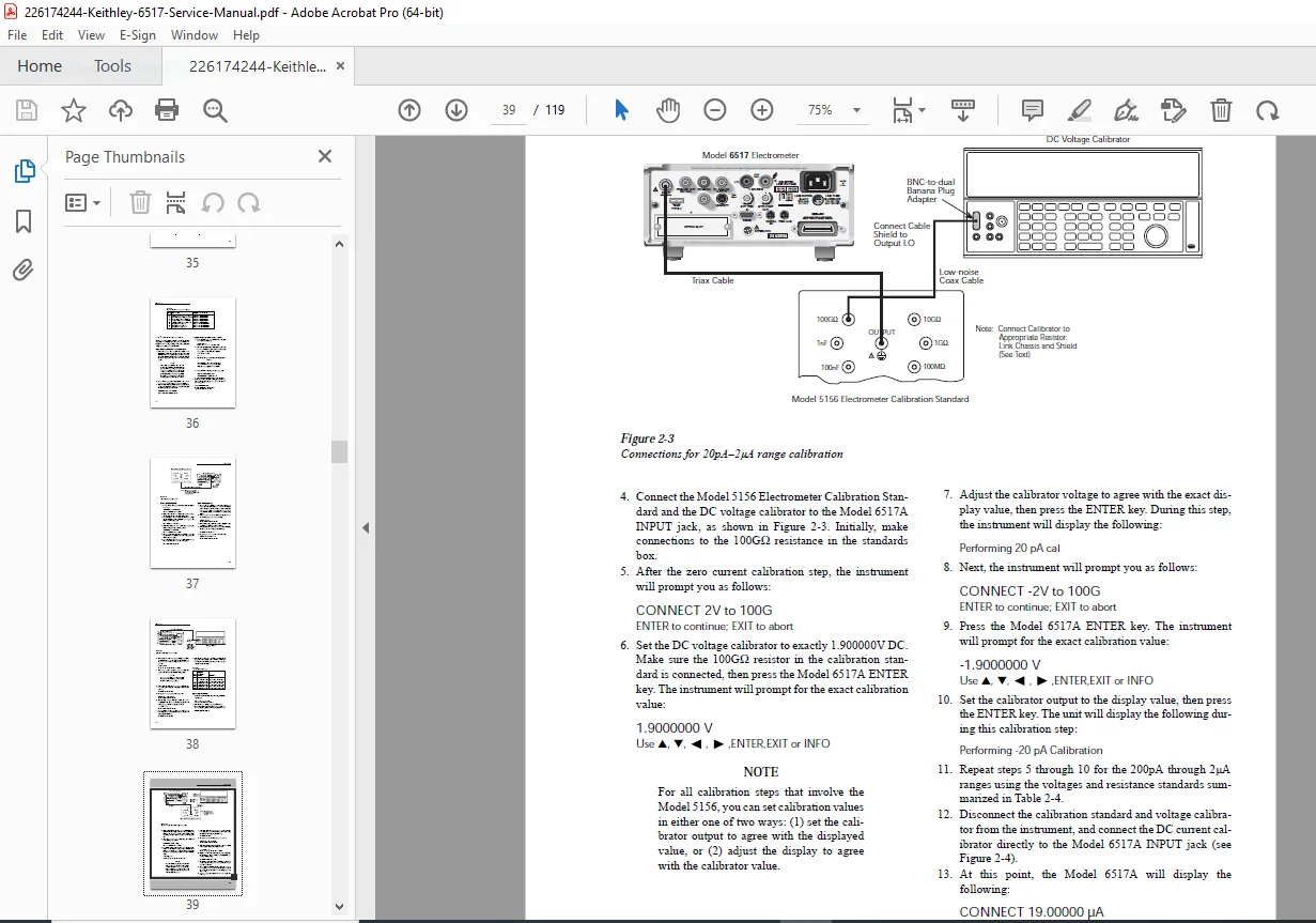
- Offset Voltage and Bias Current Calibration
- Front panel offset calibration
- IEEE-488 bus offset calibration
- Comprehensive Meter Verification Procedures
- DC volts verification (all ranges)
- DC amps verification (20pA to 20mA ranges)
- Coulombs verification procedures
- Ohms verification (2MΩ to 200TΩ ranges)
- Voltage Source Verification
- Temperature Verification Procedures
- Humidity Verification Procedures
SECTION 2: CALIBRATION (Pages 2-1 to 2-23)
- Calibration Introduction & Environmental Requirements
- Line Power Requirements & Warm-up Period
- Recommended Calibration Equipment Specifications
- Calibration Lock/Unlock Procedures
- Front panel calibration lock
- IEEE-488 bus calibration lock status
- Calibration Error Reporting
- Front panel error messages
- IEEE-488 bus error codes
- Front Panel Calibration Procedures
- Step-by-step calibration summary
- Complete front panel calibration procedure
- IEEE-488 Bus Calibration
- Calibration command reference
- Comprehensive IEEE-488 calibration procedure
- Single-Point Calibration
- Front panel single-point calibration
- IEEE-488 bus single-point calibration
- Programming Calibration Dates
SECTION 3: CALIBRATION COMMAND REFERENCE (Pages 3-1 to 3-18)
- Complete Command Summary
- Miscellaneous Commands
- :INIT, :LOCK, :SWITCH?, :SAVE, :DATE, :NDUE, :DATA?, :OPT?, :CALTEMP
- Meter Calibration Commands
- Offset commands
- Volts function calibration commands
- Amps calibration commands
- Coulombs calibration commands
- Voltage Source Calibration Commands
- Temperature Calibration Commands
- Humidity Calibration Commands
- Calibration Error Detection & Handling
- Error query commands
- Detecting calibration errors
- Calibration step completion detection
- Using *OPC? query and *OPC command
- Generating SRQ on calibration complete
SECTION 4: ROUTINE MAINTENANCE (Pages 4-1 to 4-2)
- Line Voltage Selection Procedures
- Line Fuse Replacement Instructions
- INPUT Connector Cleaning Procedures
- Firmware Update Procedures
SECTION 5: TROUBLESHOOTING (Pages 5-1 to 5-13)
- Repair Considerations & Power-On Test
- Front Panel Diagnostic Tests
- KEYS test
- DISPLAY PATTERNS test
- Character set test
- Principles of Operation
- Display board operation
- Power supply circuitry
- Digital board functions
- Analog board operation
- Circuit Board Checks & Diagnostics
- Display board checks
- Power supply checks
- Digital board checks
- Analog board checks
- Complete Block Diagrams
- Overall Model 6517A block diagram
- Display board block diagram
- Power supply block diagram
- Digital board block diagram
- Analog board block diagram
- Preamp configuration diagrams
SECTION 6: DISASSEMBLY (Pages 6-1 to 6-5)
- Handling and Cleaning Precautions
- PC board handling procedures
- Solder repair guidelines
- Static-Sensitive Device Handling
- Case Cover Removal Instructions
- PC Board Removal Procedures
- Digital board removal
- A/D converter board removal
- Analog board removal
- Front Panel Disassembly
- Main CPU Firmware Replacement
- Instrument Re-assembly Procedures
- Assembly Drawings
SECTION 7: REPLACEABLE PARTS (Pages 7-1+)
- Complete Parts Lists
- Ordering Information
- Factory Service Contact Information
- Component Layout Diagrams
APPENDICES
- Appendix A: Complete Specifications
- Appendix B: Calibration Messages Reference
- Appendix C: Calibration Command Summary
🔧 KEY TECHNICAL FEATURES COVERED
Measurement Functions:
- DC Voltage Measurement – Complete calibration for all ranges
- DC Current Measurement – 20pA to 20mA range calibration
- Resistance Measurement – 2MΩ to 200TΩ (Tera-ohms)
- Charge Measurement – Coulombs verification and calibration
- Temperature Measurement – Calibration procedures
- Humidity Measurement – Complete verification procedures
Calibration Capabilities:
- Offset Voltage Calibration – Front panel and IEEE-488 methods
- Bias Current Calibration – Ultra-low current calibration
- Multi-Point Calibration – Comprehensive range calibration
- Single-Point Calibration – Quick recalibration procedures
- Voltage Source Calibration – Internal source verification
Communication & Control:
- IEEE-488 (GPIB) Interface – Complete command reference
- Remote Calibration – Full IEEE-488 bus calibration procedures
- Automated Calibration – Programming calibration sequences
- Error Handling – Comprehensive error detection and reporting
🎯 WHO NEEDS THIS MANUAL?
- Biomedical Equipment Technicians – Servicing medical instrumentation
- Calibration Laboratory Technicians – NIST-traceable calibration services
- Electronics Service Professionals – Precision instrument repair
- Metrology Engineers – Standards laboratory equipment maintenance
- Research Laboratory Technicians – Scientific instrument calibration
- Quality Control Managers – ISO/IEC 17025 compliance documentation
- Field Service Engineers – On-site electrometer repair and calibration
⚡ CRITICAL REPAIR & CALIBRATION INFORMATION
This Keithley electrometer service manual includes:
✓ Performance Verification Limits – Exact specifications for acceptance testing
✓ Calibration Equipment Requirements – Recommended test equipment with specifications
✓ Detailed Connection Diagrams – 11 figures showing proper test connections
✓ Step-by-Step Calibration Procedures – Both manual and automated methods
✓ Troubleshooting Block Diagrams – Complete signal flow and circuit analysis
✓ Component-Level Diagnostics – Board-level troubleshooting procedures
✓ Parts Lists with Part Numbers – OEM replacement component identification
✓ Safety Precautions – High-voltage safety and ESD protection
✓ Firmware Update Procedures – Main CPU firmware replacement instructions
✓ IEEE-488 Programming Reference – Complete SCPI command set for calibration
💡 TECHNICAL HIGHLIGHTS
Precision Measurement Ranges:
- Voltage: Ultra-low voltage measurement capabilities
- Current: From 20 picoamps (20pA) to 20 milliamps (20mA)
- Resistance: Up to 200 Tera-ohms (200TΩ) – extreme high resistance
- Charge: Coulomb measurement for capacitance and charge analysis
Advanced Features:
- Offset Compensation – Eliminate measurement errors from offset voltage and bias current
- Programmable Calibration – IEEE-488 remote calibration capability
- Multi-Range Verification – Complete procedures for all measurement ranges
- Temperature Compensation – Built-in temperature measurement and calibration
🔍 WHAT MAKES THIS MANUAL ESSENTIAL?
The Keithley 6517A electrometer repair manual provides the ONLY official source for:
- Factory Calibration Standards – Exact procedures used by Keithley service centers
- Performance Verification Limits – Official acceptance criteria for all functions
- IEEE-488 Calibration Commands – Complete SCPI command reference
- Circuit Board Diagnostics – Component-level troubleshooting with block diagrams
- OEM Parts Identification – Official Keithley replacement part numbers
- Firmware Update Procedures – Main CPU firmware replacement instructions
📱 PERFECT FOR:
- ISO 17025 Accredited Calibration Labs – Official procedures for accreditation compliance
- Medical Device Service Centers – Maintaining biomedical test equipment
- University Research Facilities – Supporting scientific research instrumentation
- Electronics Manufacturing – Production test equipment calibration
- Military & Defense Contractors – Precision measurement equipment maintenance
- Semiconductor Facilities – Clean room instrumentation calibration
🌟 INSTANT DOWNLOAD – START SERVICING TODAY!
Stop wasting time with incomplete service information! This genuine Keithley factory service manual gives you everything needed to properly calibrate, verify, troubleshoot, and repair the Model 6517/6517A Electrometer. With 119 pages of detailed procedures, calibration commands, parts lists, and circuit diagrams, you’ll have the confidence to tackle any service issue. Download now and restore your electrometer to factory specifications within hours, not days!
Pricing Rationale:
- Specialized precision measurement instrument (electrometer)
- 119 pages of comprehensive technical content
- Essential calibration lab documentation
- Complete IEEE-488 programming reference
- Official factory service procedures
- Niche biomedical/metrology market
- High-value calibration command reference
- Critical for ISO 17025 compliance
- Limited availability of genuine Keithley documentation