Kenwood TK-5710 / TK-5710H P25 VHF Transceiver Service Manual PDF
Original price was: $95.00.$18.95Current price is: $18.95.
Factory Service Manual for Kenwood TK-5710(B) / TK-5710H(B) VHF APCO P25 Mobile Radios. Includes installation, system setup, realignment & tuning, self-programming mode, PC programming, disassembly & repair, circuit description, semiconductor data, PCB layouts, schematics, interconnection diagrams, level & block diagrams, parts list, exploded views, accessories and full alignment procedures. For professional radio technicians.
Description
Kenwood TK-5710 / TK-5710H P25 VHF Transceiver Service Manual PDF DOWNLOAD
Description
This is the official Kenwood TK-5710 / TK-5710H Service Manual (Lead-Free Solder Edition) — the complete factory maintenance, alignment, and repair reference for the TK-5710 50W and TK-5710H 110W VHF APCO P25 transceiver platforms.
Designed for two-way radio service engineers, communications technicians, field depots, and bench repair labs, this manual provides full servicing theory, diagnostics, installation guidance, and board-level maintenance.
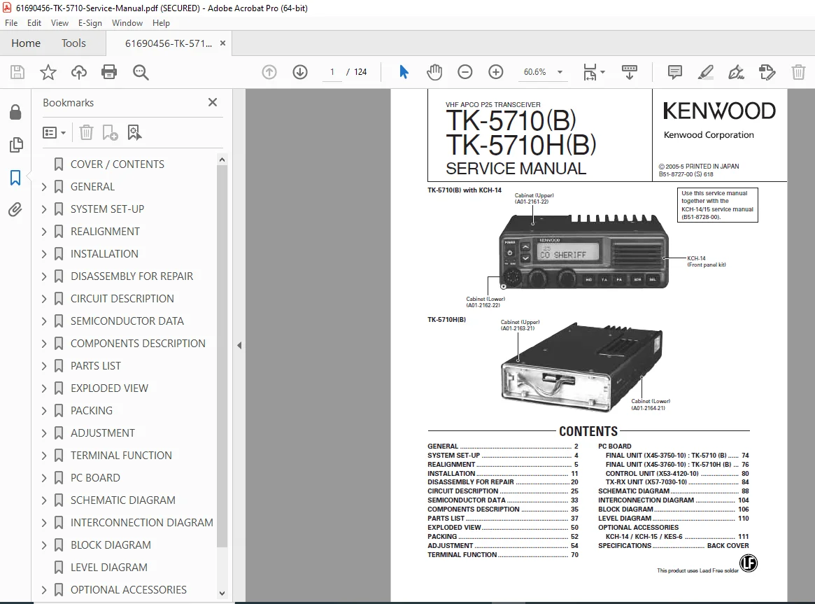
The contents page on p.1 lists all major sections, including General, System Set-Up, Realignment, Installation, Disassembly for Repair, Circuit Description, Semiconductor Data, Component Descriptions, Parts List, Exploded Views, Packing, Adjustment, Terminal Functions, PCB Layouts, Schematics, Interconnection Diagrams, Block & Level Diagrams, and Optional Accessories.
✅ Models Covered
TK-5710(B) – 50W VHF (136–174 MHz)
TK-5710H(B) – 110W VHF (136–174 MHz)
Supports:
Analog FM
APCO Project 25 (P25)
Mixed Mode operation
🧭 Structured Contents
GENERAL (pp.2–3)
Safety precautions & FCC licensing notes
Pre-installation inspection & checkout
Receiver & transmitter verification
Grounding & RF safety
Technician qualification notes
SYSTEM SET-UP (p.4)
Covers controller & remote configurations:
KCH-14 basic front panel kit
KCH-15 full-featured head
KRK-5 single control remote kit
KRK-6DH dual control head kit
Control cables & configuration workflows
Programming requirements using KPG-95D + KPG-43
Flow diagrams show controller pairing & wiring paths.
REALIGNMENT & TUNING (pp.5–10)
Includes:
User / Dealer / PC / Clone / Firmware modes
Panel test & tuning modes
PC tuning workflows
Firmware programming & baud options
Clone mode & password handling
Self-Programming Mode flow chart (diagram on p.10)
Channel personality / NAC / QT-DQT / APCO rules
INSTALLATION (pp.11–19)
Step-by-step illustrated procedures:
Front panel kit installation
Keytop replacement legend table
KRK-5 remote mount assembly
Dual-head KRK-6DH configuration
Ignition sense cable KCT-18
Voice Guide & Storage Unit VGS-1
Voice scrambler board (connector & solder type)
ANI board installation
External speaker wiring (KES-5 / KES-6)
13W audio upgrade jumper instructions
PA speaker operation
Horn alert relay lines HR1 / HR2
Images show connector pinouts, routing & gasket sealing.
DISASSEMBLY FOR REPAIR (pp.20–24)
Exploded & procedural teardown:
Upper / lower case removal
Shielding & packing removal
TX-RX Unit (X57-7030) removal
Final Unit (X45-3750 / X45-3760) removal
Control Unit (X53-4120) removal
Power terminal & accessory cable removal
Waterproof sheet & lubricant placement
Case screw tightening sequence
Great reference for bench servicing & field repair.
CIRCUIT & COMPONENT SECTIONS
Includes:
Circuit Description (functional theory)
Semiconductor Data tables
Component Descriptions
Terminal Functions
PARTS & DIAGRAM SECTIONS
Complete Parts List
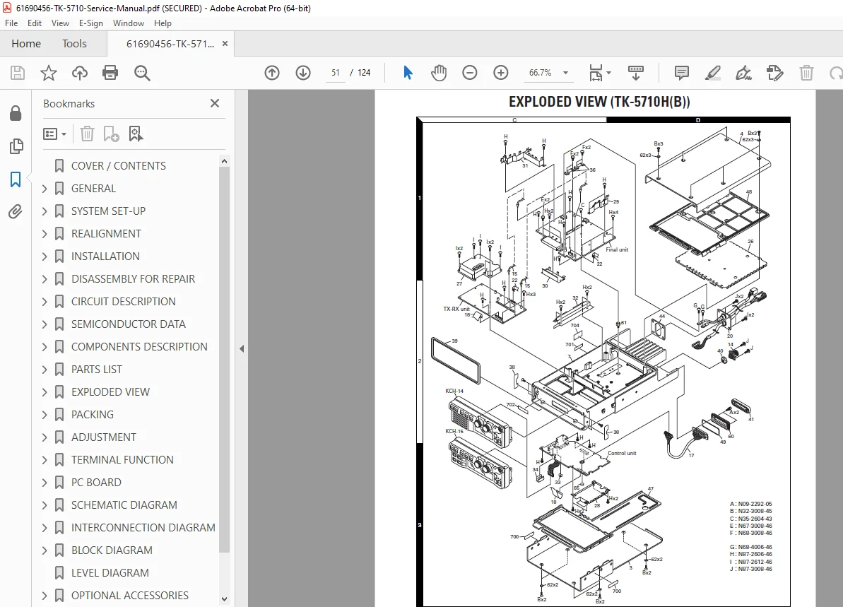
Exploded View Drawings
Packing list
PCB Layouts for:
Final Unit
Control Unit
TX-RX Unit
Schematic Diagrams
Interconnection Diagrams
Block Diagrams
Level Diagrams
Perfect for board-level diagnostics and radio restoration.
📄 File Details
| Field | Details |
|---|---|
| Manual Name | Kenwood TK-5710(B) / TK-5710H(B) Service Manual |
| Models Covered | TK-5710 50W • TK-5710H 110W • VHF APCO P25 |
| Frequency Range | 136–174 MHz |
| Year / Print Code | © 2005 — B51-8727-00 |
| Manual PDF Quality | OEM factory PDF — searchable, bookmarked, diagrams & schematics |
| Number of Pages | ~124 pages |
Owning this manual means you’re working with factory-approved alignment data, wiring maps, and PCB layouts — not guess-work or generic repair notes. It’s an essential reference for anyone servicing, programming, or restoring TK-5710 series radios.