Kenworth Truck T170 T270 T370 & Hybrid 2011 Body Builders Manual PDF
$27.95
Kenworth Truck T170 T270 T370 & Hybrid 2011 Body Builders Manual – PDF DOWNLOAD
Description
Kenworth Truck T170 T270 T370 & Hybrid 2011 Body Builders Manual – PDF DOWNLOAD
FILE DETAILS:
Kenworth Truck T170 T270 T370 & Hybrid 2011 Body Builders Manual – PDF DOWNLOAD
Language : English
Pages : 179
Downloadable : Yes
File Type : PDF
IMAGES PREVIEW OF THE MANUAL:
TABLE OF CONTENTS:
Kenworth Truck T170 T270 T370 & Hybrid 2011 Body Builders Manual – PDF DOWNLOAD
SECTION 1 — INTRODUCTION
SCOPE 1-1
SECTION 2 — SAFETY AND COMPLIANCE
SAFETY SIGNALS 2-1
Warnings, Cautions, and Notes 2-1
FEDERAL MOTOR VEHICLE SAFETYSTANDARDS COMPLIANCE 2-2
Incomplete Vehicle Certification 2-2
Noise and Emissions Requirements 2-3
Fuel System 2-4
Compressed Air System 2-4
Exhaust and Exhaust After-treatment System 2-4
Cooling System 2-5
Electrical System 2-6
Air Intake System 2-8
Charge Air Cooler System 2-8
SECTION 3 — DIMENSIONS
ABBREVIATIONS AND DEFINITIONS 3-1
overall dimensions 3-3
Detail Views 3-5
Detail Views 3-6
Back of Cab: Flush Mounted Flood Lamps – T270/370 3-6
Detail Views 3-7
Crossmember Locations – T170 3-7
Detail Views 3-8
Crossmember Locations – T170 3-8
COMPONENTS 3-9
Frame Rail Configurations – T170/270/370 3-9
Battery Box – T270/370 3-10
Battery/Tool Box – T270/370 3-10
22-inch Fuel Tanks — T270/370 3-11
245-inch Fuel Tanks — T270/370 3-11
Rectangular Fuel Tank 3-12
Battery Box – T270/370 3-13
Battery/Access Step – T170 3-13
Horizontal Exhaust/Muffler 3-14
Step/DPF Box Assembly RH Under Cab – T270/370 3-15
Horizontal Muffler-Vertical Tailpipe on Cab 3-15
RH Back of Cab Independent Muffler — T270/T370 3-16
RIDE HEIGHTS 3-17
REAR SUSPENSION LAYOUTS 3-19
Kenworth AG210L Single Rear Axle 3-19
Kenworth AG400L tandem Rear Axle 3-20
Reyco 79KB Single Rear Axle 3-21
Optional Reyco 79KB Suspensions 3-21
Reyco 102 Tandem Rear Axle 3-22
Optional Reyco 102 Suspension 3-22
HENDRICKSON HAS Single Rear Axle 3-23
Optional Hendrickson HAS Single Suspensions 3-23
HENDRICKSON Primaax Single Rear Axle 3-24
Optional Hendrickson Promaax Single Suspensions 3-24
Hendrickson HAS Tandem Suspension 3-25
Optional Hendrickson HAS Tandem Suspensions 3-25
Hendrickson RT Tandem Suspension 3-26
Optional Hendrickson RT Tandem Suspensions 3-26
Chalmers 854-40 Tandem Suspension 3-27
Optional Chalmers Tandem Suspensions 3-27
TIRE DATA 3-28
FRAME AND CAB RELATED HEIGHTS 3-28
GROUND CLEARANCES 3-28
PTO Clearances 3-33
SECTION 4 — exhaust & aftertreatment
Exhaust and After-treatment Information 4-1
General Guidelines for DEF System 4-3
Installation Requirements and Dimensions for DEF System 4-3
Measurement Reference Points 4-4
General Exhaust Information 4-9
EXHAUST INFORMATION 4-18
SECTION 5 — frame layouts
FRAME LAYOUTS 5-1
Common Optional Components 5-2
FRAME LAYOUT INDEX 5-4
SECTION 6 — BODY MOUNTING
FRAME INFORMATION 6-1
CRITICAL CLEARANCES 6-1
Rear Wheels and Cab 6-1
Body Mounting Using Brackets 6-2
Frame Sill 6-2
Brackets 6-2
Mounting Holes 6-3
Frame Drilling 6-3
Hole Location Guidelines 6-4
BODY MOUNTING USING U–BOLTS 6-4
Spacers 6-4
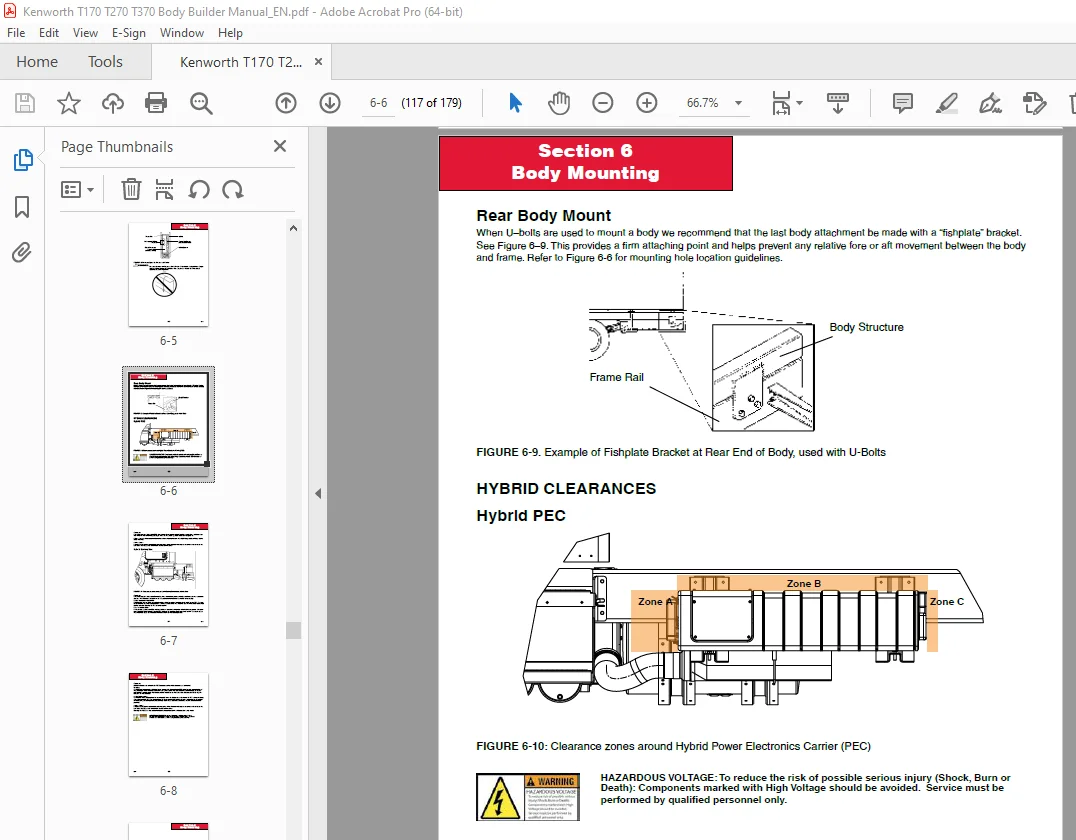
Rear Body Mount 6-6
Hybrid Clearances 6-6
Hybrid PEC 6-6
Hybrid Battery Box 6-7
SECTION 7 — FRAME MODIFICATIONS
FRAME MODIFICATIONS 7-1
Introduction 7-1
DRILLING RAILS 7-1
Location and Hole Pattern 7-1
MODIFYING FRAME LENGTH 7-2
Frame Insert 7-2
Changing Wheelbase 7-3
Crossmembers 7-4
WELDING 7-5
TORQUE REQUIREMENTS 7-7
SECTION 8 – ELECTRICAL
ELECTRICAL 8-1
ACCESSING GAUGES AND SWITCHES 8-10
OPTIONAL SWITCHES, AIR VALVES AND GAUGES 8-20
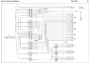
ADDITIONAL SPARE CIRCUITS 8-23
Additional Spare Circuits for Wiring 8-23
optional body builder harness 8-24
Circuits Wired Through the Ignition 8-26
Connecting Ignition Circuits 8-26
Circuits Wired to Battery 8-26
body builder power distribution center 8-29
INSTALLING A THIRD BATTERY (Not available on hybrid) 8-30
Body Builder’s Manual
Contents
III
WIRING FOR A LIFTGATE 8-31
Liftgate Power Source 8-31
Connecting the Liftgate Power 8-32
270 Amp Alternator (Recommended Hookup) 8-33
Engine Connections 8-33
REMOTE PTO/THROTTLE HARNESS 8-34
TRAILER CABLE CONNECTIONS 8-40
SECTION 9 – ROUTING
ROUTING 9-1
ROUTING REQUIREMENTS 9-2
Routing of Wires and Hoses near Exhaust System 9-4
APPENDIX A – VEHICLE IDENTIFICATION
VIN Location A-1
Chassis Number Locations A-1
vehicle identification labels A-2
Tire/Rim and Weight Rating Data Label A-2
Incomplete Vehicle Certification Label A-2
Components and Weights Label A-2
Noise Emission Label A-3
Paint Identification Label A-3
COMPONENT IDENTIFICATION A-3
Engine Identification A-3
Transmission Identification A-4
Front Axle Identification A-4
Rear Axle Identification A-4
S.V 22/02/2025