Kia Optima 2001 2.4L DOHC Engine Service Repair Workshop Manual PDF
Original price was: $120.00.$16.95Current price is: $16.95.
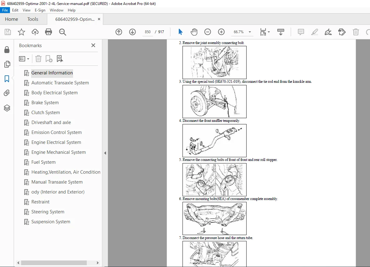
Complete official factory service manual for 2001 Kia Optima (Magentis/MS) with 2.4L DOHC gasoline engine. This comprehensive 917-page workshop manual covers all systems across 21 detailed sections including engine mechanical, fuel injection, automatic and manual transaxles, electrical systems, suspension, brakes, body, heating/AC, and more. Includes troubleshooting charts, wiring diagrams, torque specifications, special tools, maintenance schedules, and step-by-step repair procedures with detailed illustrations.
Description
Kia Optima 2001 2.4L DOHC Engine Complete Service Repair Workshop Manual PDF DOWNLOAD
DESCRIPTION
Official Kia Optima 2001 Factory Service Repair Manual
This is the complete official factory service manual for the 2001 Kia Optima (also known as Magentis/MS) equipped with the 2.4L DOHC gasoline engine (Engine Code: G 2.4 DOHC). Published by Kia Motors Corporation, this comprehensive workshop manual provides complete technical documentation for professional technicians, mechanics, and serious automotive enthusiasts performing maintenance, diagnosis, and repair on these vehicles.
Vehicle Coverage:
Model: Kia Optima (Magentis/MS) – Model Year 2001
Chassis Code: GD (sedan body type)
Engine: G 2.4 DOHC (2.4-liter, inline 4-cylinder, DOHC)
Transaxles:
- M5G Series 5-speed Manual Transaxle
- F4A42/F4A33 4-speed Automatic Transaxle
- KM 175-5/KM 175-6 Automatic Transaxles
Engine Specifications:
- Type: Inline 4-cylinder, 4-stroke gasoline
- Configuration: SIRIUS II DOHC Engine
- Displacement: 2.4 liters (2,351cc – 2,493cc variants)
- Valvetrain: Double Overhead Camshaft (DOHC)
- Fuel System: Multi-Point Fuel Injection (MFI)
- Emission Control: Catalytic converter equipped
Complete Manual Organization – 21 Comprehensive Sections:
SECTION 1: GENERAL INFORMATION
How to Use This Manual:
- Section organization and navigation system
- Index usage for quick component location
- Troubleshooting table explanation
- Definition of terms (Standard Value, Service Limit)
- Warning, Caution, and Note symbols
- Abbreviation key
Vehicle Identification:
- VIN Location and Decoding:
- 17-digit VIN structure explained
- World manufacturer identifier (KNE/KNA)
- Vehicle type, body type, engine type codes
- Transaxle and model year identification
- Plant location codes
- Sequential number system
- Engine Identification Number:
- 11-digit engine ID structure
- Engine fuel type codes (G=Gasoline, L=LPG, D=Diesel)
- Engine range and development codes
- Capacity codes and production year
- Serial number format
- Transaxle Identification:
- Manual transaxle code structure
- Automatic transaxle code system
- Final gear ratio identification
- Production year and classification
Protection and Safety:
- Vehicle protection procedures (fender, seat, floor covers)
- Hood support safety
- Basic safety warnings when working on vehicle
- Proper jacking procedures and positions
- Wheel blocking requirements
- Jack stand placement
Tool Preparation:
- Special tools listing and requirements
- Measuring equipment specifications
- Standard tool requirements
Service Procedures:
- Part removal best practices
- Disassembly procedures
- Parts inspection guidelines
- Parts arrangement and identification
- Cleaning methods for reusable parts
- Genuine parts requirements
- Reassembly torque specifications
- One-time use parts (seals, gaskets, O-rings, lock washers, cotter pins)
- Sealant and lubrication application
Electrical System Precautions:
- Battery disconnect procedures
- Connector handling (locking connectors)
- Sensor and relay handling
- Rubber parts and fuel protection
Body Dimension Measurement:
- Tracking gauge usage
- Projected dimensions vs. actual-measurement dimensions
- Measurement point identification
- Probe adjustment procedures
Cable and Wire Checking:
- Terminal tightness inspection
- Corrosion checking
- Open circuit testing
- Insulation damage inspection
- Grounding verification
- Wiring routing inspection
- Wire gauge and current capacity chart
Fuse Checking:
- Blade-type fuse test tap usage
- Test lamp procedures
Electrical System Service:
- MFI and ELC system diagnostic code preservation
- Wiring harness routing and securing
- Connector installation procedures
- Heat sensitivity precautions (80°C/176°F limit)
- Wire sizing for electrical loads
Catalytic Converter Precautions
SRS (Airbag) System Components Information
Vehicle Lift and Support Locations
Standard Parts Tightening Torque Tables:
- Complete torque specifications for all standard fasteners
- Metric and SAE torque charts
Recommended Lubricants and Capacities:
- Engine oil specifications (API SG or SG/CD)
- SAE grade numbers for different temperatures
- Transaxle fluid specifications (ATF SP-II M)
- Power steering fluid (PSF-3)
- Brake fluid specifications
- Grease specifications (NLGI No.2)
- Complete capacity charts
Maintenance Service Procedures:
- Engine oil checking and replacement
- Oil filter replacement
- Belt tension checking and adjustment
- Cooling system service
- Ignition cable replacement
- Oxygen sensor replacement
- Fuel system inspection
- Manual transaxle oil service
- Automatic transaxle fluid service
- Steering linkage inspection
- Power steering fluid service
- Ball joint and boot inspection
- Brake system service (lines, pads, linings, fluid)
- Tire pressure and rotation
- Road test procedures
SECTION 2: ENGINE MECHANICAL SYSTEM
Engine Specifications:
- Complete dimensional data
- Compression ratio specifications
- Torque and horsepower curves
- Oil pressure specifications
- Valve clearances
- Timing specifications
Engine Removal and Installation:
- Complete engine removal procedures
- Engine mount locations and replacement
- Installation procedures with alignment
Cylinder Head Service:
- Cylinder head removal and installation
- Torque sequence and specifications
- Head resurfacing specifications
- Valve guide service
- Valve seat machining
- Valve spring testing
- Camshaft removal and installation
- Timing chain/belt service
Cylinder Block Service:
- Piston and connecting rod removal
- Cylinder bore measurement
- Piston ring installation
- Connecting rod bearing service
- Crankshaft service
- Main bearing replacement
- Oil pump service
Timing System:
- Timing chain/belt replacement
- Tensioner adjustment
- Timing mark alignment
- Camshaft timing verification
Lubrication System:
- Oil pump disassembly and inspection
- Oil pan service
- Oil filter housing
- Pressure relief valve testing
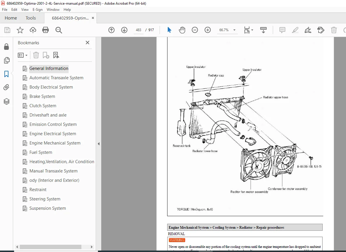
Cooling System:
- Water pump service
- Thermostat replacement
- Radiator service
- Cooling fan operation
SECTION 3: FUEL SYSTEM
Multi-Point Fuel Injection (MFI):
- System overview and operation
- Electronic control system
- Fuel pressure specifications
- Injector testing and replacement
- Fuel pump testing
- Fuel filter replacement
- Throttle body service
- Idle speed control
- Air intake system
Fuel Tank and Lines:
- Fuel tank removal and installation
- Fuel line service
- Evaporative emission control system (EVAP)
- Fuel cap testing
SECTION 4: EMISSION CONTROL SYSTEM
Emission Components:
- Catalytic converter service
- Oxygen sensor testing and replacement
- EGR system (if equipped)
- PCV system
- Evaporative emission controls
- Air injection system (if equipped)
- Emission system diagnostics
SECTION 5: AUTOMATIC TRANSAXLE SYSTEM
F4A42/F4A33 Automatic Transaxle:
- Special service tools
- Complete troubleshooting charts
- Service specifications
- Tightening torques
- Snap ring and spacer adjustments
- Removal and installation procedures
- Overhaul procedures
- Valve body service
- Torque converter service
- Clutch pack service
- Planetary gear service
- Oil pump service
- Governor and solenoid testing
- Hydraulic pressure testing
- Shift cable adjustment
- Inhibitor switch adjustment
KM 175 Series Transaxle:
- Model-specific procedures
- Final gear ratio specifications
- Component identification
SECTION 6: MANUAL TRANSAXLE SYSTEM
M5G Series 5-Speed Manual:
- Transaxle removal and installation
- Clutch system service
- Shift linkage adjustment
- Synchronizer service
- Bearing replacement
- Gear inspection
- Case and housing service
- Oil seal replacement
- Shift mechanism service
Clutch System:
- Clutch disc replacement
- Pressure plate service
- Release bearing replacement
- Clutch hydraulic system
- Master cylinder service
- Slave cylinder service
- Clutch pedal adjustment
SECTION 7: DRIVE AXLES AND DRIVESHAFTS
Constant Velocity (CV) Joints:
- Front axle shaft removal and installation
- CV joint boot replacement
- Inner and outer CV joint service
- Intermediate shaft service
- Hub and bearing service
SECTION 8: SUSPENSION SYSTEM
Front Suspension:
- MacPherson strut removal and installation
- Strut mount and bearing service
- Spring replacement
- Lower control arm service
- Ball joint replacement
- Stabilizer bar service
- Front wheel alignment specifications
Rear Suspension:
- Rear strut/shock absorber service
- Coil spring replacement
- Trailing arm service
- Lateral link service
- Stabilizer bar service
- Rear wheel alignment specifications
Wheel Alignment:
- Camber adjustment
- Caster specifications
- Toe adjustment
- Thrust angle specifications
SECTION 9: STEERING SYSTEM
Power Steering:
- Power steering pump removal and installation
- Pump pressure testing
- Steering gear removal and installation
- Rack and pinion service
- Tie rod replacement
- Steering column service
- Steering wheel removal
- Power steering hose service
- Fluid specifications and bleeding
SECTION 10: BRAKE SYSTEM
Hydraulic Brake System:
- Master cylinder service
- Brake booster testing and replacement
- Proportioning valve
- Brake line replacement
- Brake fluid specifications
Front Disc Brakes:
- Caliper removal and installation
- Brake pad replacement
- Rotor service and specifications
- Caliper overhaul
Rear Drum Brakes:
- Drum removal
- Shoe replacement
- Wheel cylinder service
- Adjusting mechanism
- Parking brake adjustment
Anti-lock Brake System (ABS) – if equipped:
- ABS component location
- Wheel speed sensor service
- ABS module testing
- Hydraulic unit service
- System bleeding procedures
SECTION 11: WHEELS AND TIRES
Tire and Wheel Service:
- Tire specifications
- Wheel specifications
- Tire pressure recommendations
- Tire rotation patterns
- Wheel balance procedures
- Tire chains and snow tires
SECTION 12: ELECTRICAL SYSTEM
Battery and Charging System:
- Battery specifications and testing
- Alternator testing procedures
- Voltage regulator testing
- Charging system diagnosis
Starting System:
- Starter motor removal and installation
- Starter testing procedures
- Solenoid testing
- Starting circuit diagnosis
Ignition System:
- Distributor service (if equipped)
- Ignition coil testing
- Spark plug specifications
- Ignition cable testing
- Ignition timing procedures
- Electronic ignition control
Lighting System:
- Headlight adjustment
- Bulb specifications
- Switch testing
- Relay locations
Wiring Diagrams:
- Complete vehicle wiring schematics
- Power distribution
- Ground locations
- Connector pin assignments
- Wire color codes
- Circuit descriptions
SECTION 13: HEATING AND AIR CONDITIONING
HVAC System:
- A/C compressor service
- Condenser and evaporator service
- Expansion valve service
- Refrigerant specifications (R-134a)
- Pressure testing procedures
- Leak detection
- System evacuation and charging
- Heater core replacement
- Blower motor service
- Control panel service
SECTION 14: BODY ELECTRICAL
Instruments and Gauges:
- Speedometer and tachometer
- Fuel gauge
- Temperature gauge
- Warning light system
- Instrument cluster removal
Wiper and Washer System:
- Wiper motor testing
- Washer pump service
- Linkage adjustment
Power Windows and Locks:
- Window motor replacement
- Door lock actuator service
- Switch testing
Audio System:
- Radio removal and installation
- Speaker service
- Antenna service
SECTION 15: SUPPLEMENTAL RESTRAINT SYSTEM (SRS/AIRBAG)
SRS Components:
- Safety precautions for airbag service
- SRS system disabling procedures
- Clock spring removal
- Airbag module replacement
- Seat belt pretensioner service
- SRS diagnostic procedures
- System reset procedures
SECTION 16: BODY
Exterior Components:
- Hood adjustment
- Fender removal and installation
- Door adjustment and alignment
- Trunk lid adjustment
- Bumper service
- Grille replacement
- Mirror replacement
Interior Components:
- Seat removal and installation
- Door panel removal
- Dashboard removal
- Center console service
- Trim panel removal
Glass and Window Service:
- Windshield replacement
- Door glass replacement
- Window regulator service
- Glass run channel service
SECTION 17: RESTRAINT SYSTEM
Seat Belts:
- Seat belt removal and installation
- Buckle testing
- Retractor service
- Anchor point specifications
SECTIONS 18-21: ADDITIONAL SYSTEMS
- Climate control system details
- Immobilizer system (if equipped)
- Diagnostic trouble codes
- Special service tools catalog
- Technical service bulletins
- Maintenance schedules
Special Features Throughout Manual:
Comprehensive Troubleshooting Charts:
- Symptom-based diagnostic trees
- Cause and remedy columns with cross-references
- Step-by-step diagnostic procedures
- Component testing specifications
Detailed Wiring Diagrams:
- Complete vehicle electrical schematics
- Power and ground distribution
- Connector locations and pin assignments
- Wire color code identification
- Circuit tracing procedures
Special Service Tools:
- Complete special tool listing with part numbers
- Tool descriptions and applications
- Alternative tool recommendations where applicable
- Measurement equipment specifications
Torque Specifications:
- Component-specific torque values
- Bolt torque sequences (cylinder head, main bearings, etc.)
- Standard fastener torque charts
- One-time use fastener identification
Fluid Specifications and Capacities:
- Engine oil type and capacity
- Transaxle fluid type and capacity
- Brake fluid specifications
- Power steering fluid type
- Coolant capacity and mixture ratio
- A/C refrigerant type and quantity
Maintenance Intervals:
- Scheduled maintenance procedures
- Service interval charts
- Inspection procedures
- Replacement intervals for filters, fluids, belts
Step-by-Step Procedures with Illustrations:
- Detailed photographs showing component locations
- Exploded view diagrams
- Assembly sequence illustrations
- Connector identification photos
- Measurement procedures with tools
File Details:
- Manual Title: Kia Optima (Magentis/MS) Service Manual
- Model Year: 2001
- Engine: G 2.4 DOHC (2.4L gasoline)
- Chassis Code: GD (sedan)
- Manual Organization: 21 comprehensive sections
- PDF Quality: High-resolution factory documentation
- Total Pages: 917 pages
- Language: English
- File Format: Searchable PDF with detailed photographs, diagrams, and technical illustrations
- Publisher: Kia Motors Corporation
- Document Type: Official Factory Service and Repair Manual
Why This Manual is Essential for Kia Optima Service:
This service manual is the complete factory-authorized resource for anyone maintaining or repairing the 2001 Kia Optima with 2.4L DOHC engine. Whether you’re a professional Kia technician at a dealership, an independent import specialist, a fleet maintenance manager, or a dedicated Kia owner performing your own service, this manual provides the authoritative technical documentation required for proper diagnostics, maintenance, and repair.
Download immediately and gain instant access to 917 pages of factory-approved service procedures, complete wiring diagrams, troubleshooting charts, torque specifications, fluid capacities, special tool identification, and step-by-step repair instructions with detailed photographs that will ensure your Kia Optima receives proper service according to manufacturer engineering standards. Master the 2.4L DOHC engine, F4A42 automatic transaxle, M5G manual transaxle, suspension systems, brake systems, electrical systems, and all vehicle systems with this comprehensive factory workshop manual!