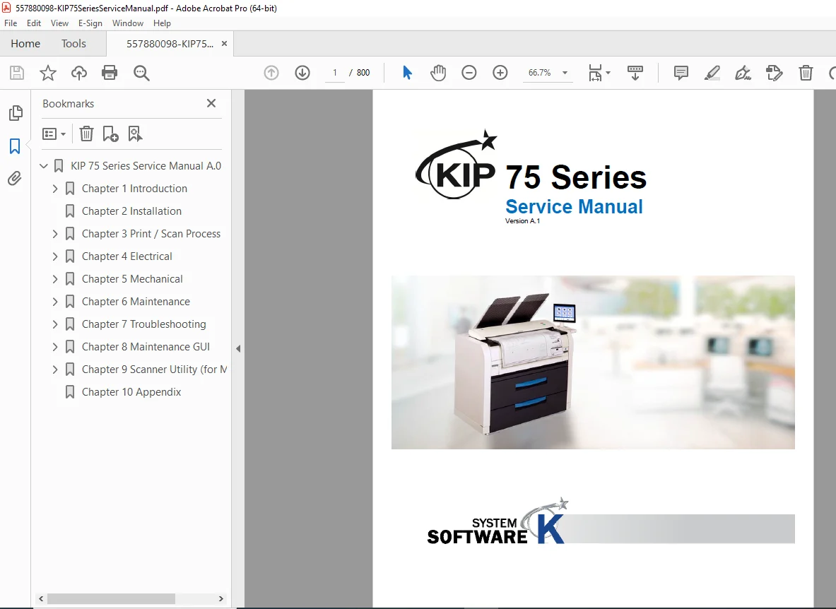
KIP 7570 Series Wide Format LED Printer MFP Service Repair Manual PDF
Original price was: $120.00.$35.95Current price is: $35.95.
Complete factory service manual for KIP 7570 Series wide format LED printer and multifunction systems. This massive 800-page technical manual covers installation, operation, maintenance, troubleshooting, and repair of KIP 7570M (MFP) and KIP 7570P (Printer) models with 2-roll and 4-roll configurations. Includes detailed electrophotographic process diagrams, electrical schematics, mechanical disassembly, calibration procedures, error code diagnostics, and comprehensive parts information. Essential for service technicians and facilities managing large format printing systems.
Description
KIP 7570 Series Wide Format LED Printer MFP Service Repair Manual PDF DOWNLOAD
DESCRIPTION
KIP 7570 Series Wide Format LED Printer/MFP – Complete Factory Service Manual
This is the official factory service manual for the KIP 7570 Series Wide Format LED Printer and Multifunction Systems – professional-grade electrophotographic imaging equipment designed for architectural, engineering, construction (AEC), and graphics industries. Published by Katsuragawa Electric Co., Ltd., this comprehensive technical manual is essential for service technicians, field engineers, and facility managers responsible for maintaining these sophisticated large format printing systems.
With an impressive 800 pages of detailed technical documentation (Version A.1, 2016), this manual provides complete coverage of system architecture, installation procedures, operational theory, maintenance protocols, and advanced troubleshooting methodologies required to keep these systems operating at peak performance.
© 2016 Katsuragawa Electric Co., Ltd.
For KIP Authorized Dealers Only
Manual Reference: K144sm
🖨️ ABOUT THE KIP 7570 SERIES
The KIP 7570 Series represents advanced wide format imaging technology utilizing LED array electrophotography with KIP HDP Plus imaging system for high-definition technical document reproduction. These systems are engineered for demanding commercial environments requiring consistent, high-quality large format output.
Key System Capabilities:
- LED Electrophotographic Technology – Precision LED array imaging
- Print Speed: 100mm per second (5.2 ppm E-size / 9.5 ppm A1 landscape)
- Maximum Print Width: 36″ (914mm)
- Maximum Print Length: 6 meters standard / up to 20 feet with options
- Resolution: 600 dpi x 2400 dpi
- Scanning Resolution: 600 dpi optical (MFP models)
- KIP HDP Technology: Zero waste toner system
- 12-inch Multi-Touch Panel: Tablet-like operation and control
Available Models:
- KIP 7570M – Wide Format MFP (Multifunction) with 2-Roll or 4-Roll configuration
- KIP 7570P – Wide Format Printer with 2-Roll or 4-Roll configuration
Print Media Capabilities:
- Bond paper, Vellum, Film
- Plain paper, Tracing paper
- Cut sheets and roll media
- Front or rear print delivery
📋 COMPREHENSIVE MANUAL CONTENTS (800 PAGES)
CHAPTER 1 – INTRODUCTION (Pages 1-1 to 1-18)
- Features
- LED Array Electrophotographic System
- Four Model Configurations (2-roll/4-roll, MFP/Printer)
- KIP HDP Technology – Zero waste toner generation
- KIP HDP Plus Imaging System
- High definition line reproduction
- Distinctive grayscale rendering
- Consistent black density
- Density Compensation Process – Consistent output across environments
- High-Speed Performance – 100mm/sec printing
- Wide Media Range – 11″ to 36″ widths
- Flange-Type Loading – Easy media handling
- 600dpi Print Resolution with enhanced scanning
- Advanced KIP Image Process System
- File to Print / Scan to USB capabilities
- 2-Way Print Delivery – Front stacking or rear output
- Optional Finishing Devices – Auto Stacker, Online Folder
- Contactless IC Card Reader – Efficient accounting (option)
- 12″ Multi-Touch Panel – Tablet-like interface
- Specifications – General
- Model configurations and nomenclature
- Power Consumption:
- Maximum: 3120W or less (scanner/controller included)
- Low power mode: Energy Star compliant
- Acoustic Noise:
- Ready: Max 50dB
- Printing: Max 57dB
- Ozone Emission: Max 0.05ppm (UL Standard)
- Dimensions:
- MFP Model: 1356mm (W) x 720mm (D) x 1185mm (H)
- Printer Model: 1356mm (W) x 720mm (D) x 1105mm (H)
- Weight:
- MFP Model: Approx. 283kg (624 lbs) for 4-roll
- Printer Model: Approx. 266kg (587 lbs) for 4-roll
- Environmental Conditions:
- Temperature: 10°C to 32°C (50°F to 89.6°F)
- Humidity: 15% to 85% RH
- Interface: Network (10/100/1000 BASE-T), USB 2.0
- Power Rating: 220-240V ±6%/-10%, 50/60Hz, 13A
- Specifications – Printer Part
- Printing Method: LED Array Electrophotography
- Photoreceptor: Organic Photoconductive Drum
- Print Speed: 100mm per second
- 5.2 ppm E-size / 10 ppm D Landscape (Inch)
- 4.9 ppm A0 / 9.5 ppm A1 Landscape (Metric)
- Print Head: LED Array
- Resolution: 600 dpi x 2400 dpi
- Print Width:
- Maximum: 914mm (36″)
- Minimum: 297mm (11″) roll / 210mm (8.5″) cut sheet
- Print Length:
- Standard Maximum: 6,000mm (19.7 ft) for 36″/A0 wide
- Option: Up to 200,000mm with extended length capability
- Minimum: 210mm (8.5″)
- Paper Feeding: 2-Roll or 4-Roll Decks + Manual Bypass Feeder
- Warm-up Time: Less than 4 minutes
- First Print Time: 24 seconds (D/A1 Landscape, Front Stacking)
- Fusing Method: Heat and Pressure Rollers
- Development: Dry type non-magnetic mono-component toner
- Supported Media: Bond, Vellum, Film, Plain Paper, Tracing Paper
- Consumables Storage: 0°C to 35°C, 35% to 85% RH
- Specifications – Scanner Part (MFP Models)
- Scanning Method: Contact Image Sensor (CIS)
- Light Source: LED (R/G/B) – 5 pieces of A4-sized CIS
- Scanning Speed at 600dpi:
- Monochrome: 65mm/s
- Grayscale: 65mm/s
- Color: 22mm/s
- Original Setting: Face up, center alignment
- Scan Width:
- Maximum: 914.4mm (36″)
- Minimum: 210mm
- Scan Length:
- Maximum: 6,000mm (19.7 ft) including margins
- Minimum: 210mm (8.5″) including margins
- Optical Resolution: 600 dpi
- Digital Resolution: 200 / 300 / 400 / 600 dpi
- Original Transport: Sheet-through type
- Original Thickness:
- Maximum: 1.60mm
- Minimum: 0.05mm
- Appearance and Component Identification
Front View Components:
- Main Switch
- Original Guides
- User Interface (12″ Touch Screen)
- Scan Abort Button
- Start Button
- Scanner Unit (MFP models)
- Toner Hatch / Original Table
- Engine Unit Open Lever
- Bypass Feeder
- Roll Deck
- Print Tray
- LED Indicator
- USB Port (USB 2.0, 5VDC max)
Rear View Components:
- Paper Exit Door
- LAN Port
- Dehumidify Heater Switch (optional kit)
- Breaker
- Inlet Socket
- USB Port for service/options
- Specifications for Scan Originals (MFP Models)
- Acceptable original dimensions
- Standard documents
- Special documents handling
- “Do Not Scan” originals list
- Specifications for Printing Media
- Papers not available to use
- Proper storage conditions
- Environmental condition handling
- Curl management
- Media conditioning requirements
CHAPTER 2 – INSTALLATION (Pages 2-1 to 2-XX)
- Installation Location Requirements
- Space requirements
- Environmental specifications
- Power supply verification
- Network infrastructure
- Ventilation considerations
- Unpacking Procedures
- Safe handling instructions
- Packing material removal
- Component inventory
- Transport damage inspection
- Setup of the Machine
- Step-by-step installation procedures
- Leveling and positioning
- Roll deck installation (2-roll or 4-roll configuration)
- Toner cartridge installation
- Developer unit installation
- Drum cartridge installation
- Waste toner container installation
- Initial Power-Up
- Pre-power checks
- System initialization
- Date/time configuration
- Network Configuration
- LAN connection setup
- IP address assignment
- Network protocols
- Print server configuration
- Media Loading
- Roll media installation on roll decks
- Flange-type loading mechanism
- Media threading
- Cut sheet loading
- Scanner Setup (MFP Models)
- Scanner unit installation
- Calibration requirements
- Original guide adjustment
- Optional Device Installation
- Auto Stacker setup
- Online Folder installation
- Dehumidify Kit
- IC Card Reader
CHAPTER 3 – PRINT/SCAN PROCESS (Pages 3-1 to 3-XX)
- Electrophotographic Process Overview
- LED exposure system operation
- Organic photoconductive drum characteristics
- Electrostatic imaging principles
- Image Formation Process
Charging Process
- Primary charging principles
- Charge roller operation
- Voltage control
Exposure Process
- LED array operation
- 600 dpi LED head technology
- Image data processing
- Dot formation on photoreceptor
Development Process
- Dry mono-component toner
- Development roller operation
- Toner supply mechanism
- Magnetic brush development
- KIP HDP technology – Zero waste toner
Transfer Process
- Transfer roller operation
- Paper transport timing
- Transfer voltage control
- Transfer efficiency optimization
Fusing Process
- Heat and pressure roller fusing
- Temperature control
- Fusing roller specifications
- Pressure adjustment
- Separation mechanisms
Cleaning Process
- Drum cleaning blade
- Waste toner collection
- Cleaning efficiency
- KIP HDP Plus Imaging System
- High definition line reproduction
- Grayscale rendering technology
- Density compensation
- Image quality optimization
- Scan Process (MFP Models)
CIS (Contact Image Sensor) Operation
- LED illumination (R/G/B)
- Five A4-sized CIS sensors
- Original transport mechanism
- Image capture timing
Image Processing
- A/D conversion
- Image enhancement
- Shading correction
- Resolution conversion
Data Flow
- Scanner to controller communication
- Image compression
- File format conversion
CHAPTER 4 – ELECTRICAL SYSTEM (Pages 4-1 to 4-XX)
- Power Supply System
- AC input specifications
- Power distribution
- Multiple voltage generation
- Power supply board architecture
- Voltage regulation
- Power consumption monitoring
- Control System Architecture
- Main controller board
- Print controller
- Scanner controller (MFP models)
- UI controller
- Communication between boards
- LED Print Head System
- LED array driver circuits
- 600 dpi LED head control
- Timing signals
- Image data transfer
- Head temperature monitoring
- Motor Control Systems
- Main drive motor
- Drum motor
- Development motor
- Fuser motor
- Paper feed motors
- Scanner transport motor (MFP)
- Motor driver circuits
- Position sensors
- High Voltage Power Supply
- Charging voltage generation
- Transfer voltage control
- Development bias
- Voltage monitoring circuits
- Temperature Control
- Fuser temperature control
- Thermistor monitoring
- Heater control circuits
- Safety cutoffs
- Sensor Systems
- Paper detection sensors
- Original detection sensors (MFP)
- Toner level sensors
- Drum rotation sensors
- Position detection sensors
- Environmental sensors
- Communication Interfaces
- Network interface circuits
- USB interface
- Serial communication
- I²C bus
- SPI bus
- Safety Circuits
- Door interlock switches
- Emergency stop circuits
- Thermal protection
- Overcurrent protection
CHAPTER 5 – MECHANICAL (Pages 5-1 to 5-XX)
- Mechanical Structure Overview
- Frame and chassis construction
- Access panels and covers
- Safety interlocks
- Paper Feed System
Roll Deck Mechanisms
- 2-roll and 4-roll deck configurations
- Flange-type roll holders
- Roll rotation mechanisms
- Paper width detection
- Feed roller systems
Bypass Feeder
- Cut sheet feeding mechanism
- Guide positioning
- Feed roller operation
Paper Transport System
- Registration rollers
- Transport belts
- Guide mechanisms
- Timing control
- Print Engine Components
Drum Cartridge Assembly
- Organic photoconductive drum
- Charging roller
- Cleaning blade
- Waste toner auger
- Installation and removal procedures
Developer Unit
- Development roller
- Toner supply roller
- Toner cartridge interface
- Agitator mechanisms
Toner Cartridge
- Toner storage
- Toner supply mechanism
- Installation procedures
Transfer Unit
- Transfer roller assembly
- Roller cleaning mechanisms
- Pressure adjustment
Fuser Unit
- Upper and lower fuser rollers
- Heater lamp assemblies
- Pressure mechanisms
- Separation fingers
- Temperature sensors
- Oil application system
- Scanner Mechanism (MFP Models)
- Original table
- Original feed rollers
- CIS sensor mounting
- Transport belt system
- Original guides
- Eject roller system
- Print Delivery Systems
- Front print tray
- Rear exit path
- Stacker interface (optional)
- Folder interface (optional)
- Disassembly Procedures
- Cover and panel removal
- Component access
- Subassembly removal sequences
- Special tool requirements
- Assembly Procedures
- Reverse disassembly with notes
- Critical alignment points
- Fastener torque specifications
- Adjustment Methods
- Registration adjustment
- Paper feed timing
- Fuser pressure
- Scanner transport calibration
- Density adjustments
CHAPTER 6 – MAINTENANCE (Pages 6-1 to 6-XX)
- Preventive Maintenance Schedule
- Daily maintenance tasks
- Weekly inspections
- Monthly service requirements
- Quarterly procedures
- Annual comprehensive service
- Consumable Replacement
Toner Cartridge Replacement
- Removal procedure
- Installation procedure
- Yield information
Drum Cartridge Replacement
- Service life indicators
- Replacement procedure
- Disposal guidelines
Developer Unit Replacement
- Service intervals
- Replacement procedure
Waste Toner Container
- Emptying procedures
- Replacement intervals
- Cleaning Procedures
- LED head cleaning
- Drum surface cleaning
- Transfer roller cleaning
- Fuser roller cleaning
- Paper path cleaning
- Scanner glass cleaning (MFP)
- CIS sensor cleaning
- Exterior cleaning
- Lubrication
- Lubrication points
- Lubricant specifications
- Application procedures
- Lubrication intervals
- Calibration Procedures
- Density calibration
- Color balance (if applicable)
- Scanner calibration (MFP)
- Media feed calibration
- Parts Replacement Life
- Consumable life expectancy
- Maintenance parts intervals
- Component replacement schedules
- Field Maintenance Information
- Common service tasks
- Quick reference procedures
- Service access points
CHAPTER 7 – TROUBLESHOOTING (Pages 7-1 to 7-XX)
- Systematic Troubleshooting Approach
- Problem identification
- Isolation techniques
- Diagnostic procedures
- Verification methods
- Malfunction Troubleshooting
Power Issues
- Unit does not power on
- Breaker trips
- Intermittent power
- Diagnostic procedures
Paper Feed Problems
- No paper feed
- Skewed feeding
- Multiple sheet feeding
- Paper jams
- Feed roller issues
Print Quality Issues
- Light prints
- Dark prints
- Background contamination
- White lines or streaks
- Black lines or streaks
- Uneven density
- Image defects
- Ghosting
- Toner scatter
Scanner Problems (MFP Models)
- Scan quality issues
- Feed errors
- Scanner jam
- CIS sensor problems
- Light/dark scans
- Streaks in scanned images
Communication Errors
- Network communication failure
- USB communication issues
- Controller communication problems
Error Code Troubleshooting
- Complete error code list
- Error descriptions
- Cause analysis
- Corrective actions
- Reset procedures
- Image Quality Troubleshooting
- Symptom-based diagnostics
- Sample defect images
- Cause identification
- Corrective procedures
- Mechanical Troubleshooting
- Abnormal noise diagnosis
- Vibration issues
- Component wear assessment
- Electrical Troubleshooting
- Voltage measurements
- Signal tracing
- Board-level diagnostics
- Component testing
CHAPTER 8 – MAINTENANCE GUI (Pages 8-1 to 8-XX)
- Accessing Maintenance Mode
- Service menu entry procedures
- Password protection
- Security considerations
- Auto Adjustment Functions
- Automatic density adjustment
- Automatic registration
- LED head calibration
- Scanner calibration (MFP)
- Backup Settings
- Configuration backup procedures
- Settings export
- Restore procedures
- Factory reset options
- Diagnostic Displays
- Real-time monitoring
- Sensor status displays
- Motor operation verification
- Temperature monitoring
- Voltage monitoring
- Counter Management
- Total print counter
- Component life counters
- Consumable counters
- Counter reset procedures
- Test Prints
- Diagnostic test patterns
- Calibration sheets
- Density patches
- Registration patterns
- Service Mode Functions
- Component testing
- Forced operations
- Sensor checks
- Motor tests
CHAPTER 9 – SCANNER UTILITY (Pages 9-1 to 9-XX)
- K129 Diag Tool
- Software installation
- Connection procedures
- Interface overview
- Scanner Adjustments Using K129 Diag
- CIS sensor calibration
- Shading correction
- Scanner timing adjustment
- Original detection settings
- Transport speed calibration
- Scanner Diagnostics
- Sensor testing
- LED operation verification
- Transport mechanism testing
- Image quality assessment
- Advanced Scanner Settings
- Resolution optimization
- Color balance
- Gain adjustment
- Offset correction
CHAPTER 10 – APPENDIX (Pages 10-1 to 10-800)
- Overall Circuit Diagrams
- Complete electrical schematics
- Power supply circuits
- Control circuits
- Motor driver circuits
- Sensor circuits
- Communication circuits
- Block Diagrams
- System architecture
- Signal flow
- Data paths
- Control hierarchy
- Wiring Diagrams
- Harness routing
- Connector pin-outs
- Wire color codes
- Terminal blocks
- Parts Explosion Diagrams
- Mechanical assemblies
- Component locations
- Part numbering
- Parts Lists
- Complete component inventory
- Part numbers
- Descriptions
- Quantities
- Connector Reference
- All connector locations
- Pin assignments
- Signal descriptions
- Voltage specifications
- Timing Charts
- Process timing diagrams
- Motor timing
- Sensor timing
- Communication protocols
- Adjustment Specifications
- Critical dimensions
- Clearance specifications
- Torque values
- Voltage specifications
- Temperature specifications
🔧 CRITICAL SERVICE FEATURES
✅ LED Electrophotographic Technology – Unique LED array exposure system
✅ KIP HDP Zero Waste Toner – Environmental and economical operation
✅ 800 Pages Comprehensive Coverage – Most detailed technical documentation
✅ Complete Electrical Schematics – Board-level repair capability
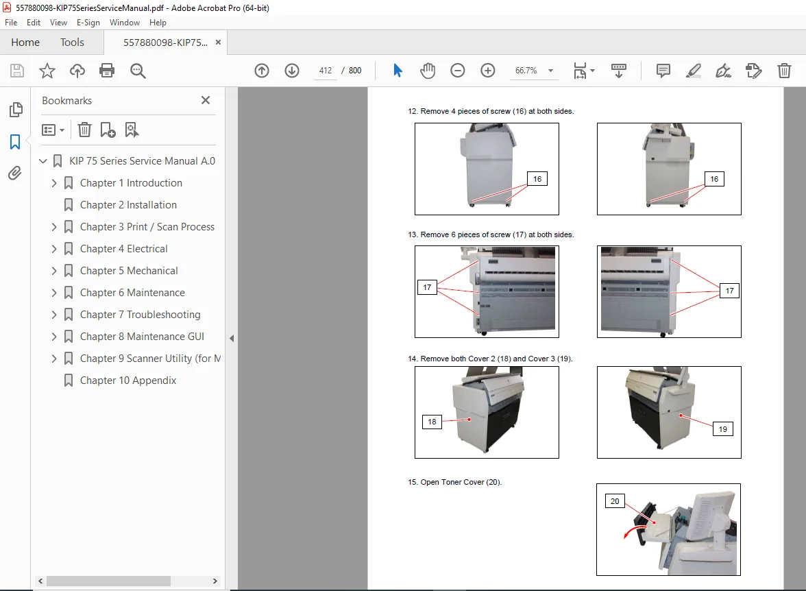
✅ Mechanical Disassembly Guides – Step-by-step procedures
✅ Image Quality Troubleshooting – Defect analysis and correction
✅ Scanner Service Documentation – Complete CIS system coverage (MFP)
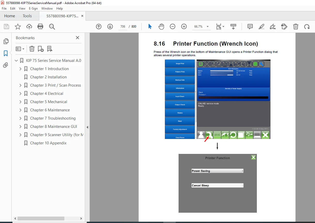
✅ Maintenance GUI Reference – Advanced service mode operations
✅ K129 Diag Tool Guide – Scanner calibration and adjustment
✅ Error Code Database – Complete diagnostic procedures
📄 FILE DETAILS
| Specification | Details |
|---|---|
| Manual Name | KIP 7570 Series Service Manual |
| Equipment Type | Wide Format LED Printer / Multifunction System |
| Models Covered | KIP 7570M (MFP), KIP 7570P (Printer) – 2 Roll & 4 Roll |
| Version | A.1 (2016) |
| Total Pages | 800 pages |
| File Format | PDF (searchable and printable) |
| PDF Quality | ⭐⭐⭐⭐⭐ Excellent – Factory service manual quality |
| Language | English |
| Manufacturer | Katsuragawa Electric Co., Ltd. (KIP) |
| Copyright | © 2016 Katsuragawa Electric Co., Ltd. |
| Authorization | For KIP Authorized Dealers Only |
| Reference Code | K144sm |
🖨️ COMPATIBLE EQUIPMENT
KIP 7570M – Wide Format MFP Models:
- 2-Roll MFP configuration
- 4-Roll MFP configuration
- Print, Copy, and Scan capabilities
- CIS scanner system included
KIP 7570P – Wide Format Printer Models:
- 2-Roll Printer configuration
- 4-Roll Printer configuration
- Print-only functionality
Print Specifications:
- Maximum width: 36″ (914mm)
- Maximum length: 6 meters standard / 20 feet optional
- Speed: 100mm/sec (5.2 ppm E-size)
- Resolution: 600 x 2400 dpi
Applications:
- Architectural drawings
- Engineering blueprints
- Construction documents
- CAD plots
- GIS maps
- Posters and signage
- Technical documentation
💡 WHO NEEDS THIS MANUAL?
- Wide Format Service Technicians – Complete repair and maintenance procedures
- KIP Authorized Dealers – Official service documentation
- In-House Technical Staff – Large corporations with KIP equipment
- Facilities Management – AEC firms, print shops, service bureaus
- Reprographics Departments – Government, education, corporate
- Print Shop Owners – Independent commercial printing businesses
- Field Service Engineers – Mobile service support
- Technical Training – Service technician education and certification
🎯 WHY THIS MANUAL IS ESSENTIAL
Authorized KIP Documentation: This is official factory service documentation for authorized dealers – the definitive technical reference for KIP 7570 Series systems.
LED Technology Expertise: KIP’s LED array electrophotographic technology requires specialized knowledge. This manual provides complete understanding of the unique imaging system.
800-Page Comprehensive Coverage: One of the most detailed service manuals available for wide format equipment, covering every aspect from basic operation to advanced board-level repair.
Minimize Downtime: In production environments, printer downtime costs money. This manual enables rapid diagnosis and repair, keeping equipment productive.
Cost Savings: Avoid expensive manufacturer service calls with complete technical documentation enabling in-house service capabilities.
Zero Waste Toner System: Understanding and servicing the unique KIP HDP technology requires proper documentation – this manual provides complete technical details.
Scanner Service Support: For MFP models, comprehensive CIS scanner coverage including K129 Diag tool procedures for calibration and adjustment.
⚙️ TECHNICAL HIGHLIGHTS
Imaging Technology:
- LED array electrophotographic system
- 600 dpi LED print head
- Organic photoconductive drum
- Dry mono-component toner
- Heat and pressure fusing
KIP HDP Technology:
- Zero waste toner generation
- High definition lines
- Distinctive grayscale
- Consistent black density
Performance:
- 100mm/sec print speed
- Less than 4-minute warm-up
- 24-second first print
- Energy Star compliant
Capacity:
- 2-roll or 4-roll configurations
- 36″ maximum width
- 6-meter standard length
- Multiple media types
⚡ INSTANT DOWNLOAD – SERVICE SUPPORT IMMEDIATELY!
Stop searching for incomplete technical information when servicing KIP 7570 wide format systems! This massive 800-page factory service manual gives you complete technical documentation for LED electrophotographic printer and MFP models. From understanding the unique KIP HDP zero-waste toner system to troubleshooting image quality defects, from mechanical disassembly to electrical schematics, from scanner calibration with K129 Diag tool to maintenance GUI operations – everything you need is here. Whether you’re a KIP authorized dealer, in-house service technician, or facility manager, this manual provides factory-level expertise for installation, maintenance, troubleshooting, and repair. Download instantly and have professional service capabilities for this sophisticated wide format imaging system!
Pricing Rationale:
- Massive 800-page comprehensive service manual
- Professional wide format equipment ($30,000-$60,000+ systems)
- Covers multiple models (7570M MFP and 7570P Printer variants)
- Unique LED electrophotographic technology documentation
- Complete electrical schematics and mechanical diagrams
- Scanner service coverage with K129 Diag tool procedures
- Authorized dealer documentation with restricted access
- Essential for commercial printing operations
- Saves thousands in manufacturer service call costs
- Specialized wide format imaging system expertise
- High-value professional equipment reference