Trusted Business
Verified & Licensed
Virus Free Files
100% Safe Downloads
Secure Payment
SSL Protected
Instant Delivery
Available Immediately
Kobelco CRAWLER CRANE CK2500-II CKE2500-II SHOP MANUAL S5JD00002ZE06 – PDF DOWNLOAD
$32.95
Kobelco CRAWLER CRANE CK2500-II CKE2500-II SHOP MANUAL S5JD00002ZE06 – PDF DOWNLOAD
Instant PDF Download
Available immediately
Save to Your Device
Download & keep forever
Antivirus Scanned
100% virus-free
Trusted Worldwide
175,000+ customers
Description
Kobelco CRAWLER CRANE CK2500-II CKE2500-II SHOP MANUAL S5JD00002ZE06 – PDF DOWNLOAD
FILE DETAILS:
Kobelco CRAWLER CRANE CK2500-II CKE2500-II SHOP MANUAL S5JD00002ZE06 – PDF DOWNLOAD
Language : English
Pages : 614
Downloadable : Yes
File Type : PDF
DESCRIPTION:
Kobelco CRAWLER CRANE CK2500-II CKE2500-II SHOP MANUAL S5JD00002ZE06 – PDF DOWNLOAD
SAFETY
PRECAUTIONS FOR INSPECTION AND MAINTENANCE
1. Service and maintenance must be performed only by authorized personnel who are qualified in compliance with a relevant law or regulation.
2. Regular maintenance or inspection should be quickly performed after shutting down the machine and ensuring safety to personnel and equipment. Post an “INSPECTION IN PROGRESS. DO NOT START.” warning sign on a readily visible location
GENERAL SAFETY PRECAUTIONS
1. Wear safety shoes, helmets and clothing suitable for the job. Also use protective goggles, mask, gloves, etc.,
as required.
2. To ensure safe and correct maintenance, carefully study this SHOP MANUAL and get fully familiar with the instructions
in it.
3. Place the machine in a safe place. Always maintain safe clearance around the machine.
4. Before starting crane operation, hold a safety meeting. Also, make agreement on standardized hand signals.
5. When inspecting or handling the battery or oil, do not use exposed flame nearby.
To avoid fire accident, only use explosion-proof lighting equipment.
6. Start an inspection or maintenance work only after shutting down the engine.
7. Certain machine components remain hot immediately after the engine is shut down. Do not touch them.
8. Before removing the radiator cap, wait until the coolant water gets sufficiently cool. Next, carefully loosen the
cap and release radiator pressure, and them remove the cap.
9. Before inspecting or maintaining an electrical system on the machine, power off the machine by, for example,
disconnecting the battery cables.
10. When working at a high lift area, always wear a safety belt.
11. When leaving the operator’s cab for an inspection or maintenance work, post an “INSPECTION IN PROGRESS.
DO NOT START.” warning sign on a readily visible location. Also, lock the cab for security.
12. Before starting a cleaning or lubrication work on the machine, always shut down the engine.
13. While adjusting tire pressure, be absolutely careful about rupture of a tire, flying of wheel part.
14. Use genuine KOBELCO replacement parts and oils only.
15. Always keep the oil containers clean. Protect them against ingress of dust or moisture. Also, fill clean, fresh
oils only.
16. Once a maintenance work is complete, clean the machine.
Protect grease nipples, breathers, and oil level gages against ingress of dust.
17. Always keep the subjects of regular inspection clean to allow problems such as oil leakage, crack, looseness,
etc., to be readily detected.
18. During car washing, do not allow high pressure steam to be directly applied to electrical components and connectors.
19. After removing O-rings, oil seals, gaskets, etc., clean the mounting seats. Then, install fresh O-rings, oil seals,
gaskets, etc. Also, remember to thinly apply oil to the seal faces of these parts before installation.
20. Before disconnecting pressurized piping, release the inside pressure.
21. CAUTIONs for repair work with welding: Turn OFF the key switch, disconnect the negative terminal on battery
to power off the electrical circuit; provide grounding within 1 meter from a weld area; in advance, remove electronic
components (for example, controller) to prevent possible damage.
22. Dispose industrial wastes according to a relevant law or regulation.
23. Extremely careful during an inspection or maintenance work under the carrier. Remember the possibility of being
crashed.
When jacking up the machine for an inspection or maintenance work, place blocks below it to prevent accidental
falling.
24. Provide positive ventilation when refilling oils or fuel, rinsing parts, or starting the engine.
SAFETY
0-29 CK2500-II, CKE2500-II
25. To remove a heavy component (20 kg or heavier), use a crane, etc. Always keep safety in mind.
26. I llegal or unauthorized, or otherwise nonconforming modification is strictly inhibited.
27. Do not allow oil or dust to deposit around the engine. Otherwise, fire accident can result.
28. Store removed attachments and components safely so that they do not drop or fall down.
29. Always use correct tools that have been well maintained.
30. To prevent personnel from being caught by a running fan, belt, shaft or the like, shut down the engine before
starting an inspection or maintenance work.
31. Battery liquid and oils are harmful to human health. If touching any of these materials, immediately wash it away.
32. Make sure to use the light oil for fuel.
IMAGES PREVIEW OF THE MANUAL:
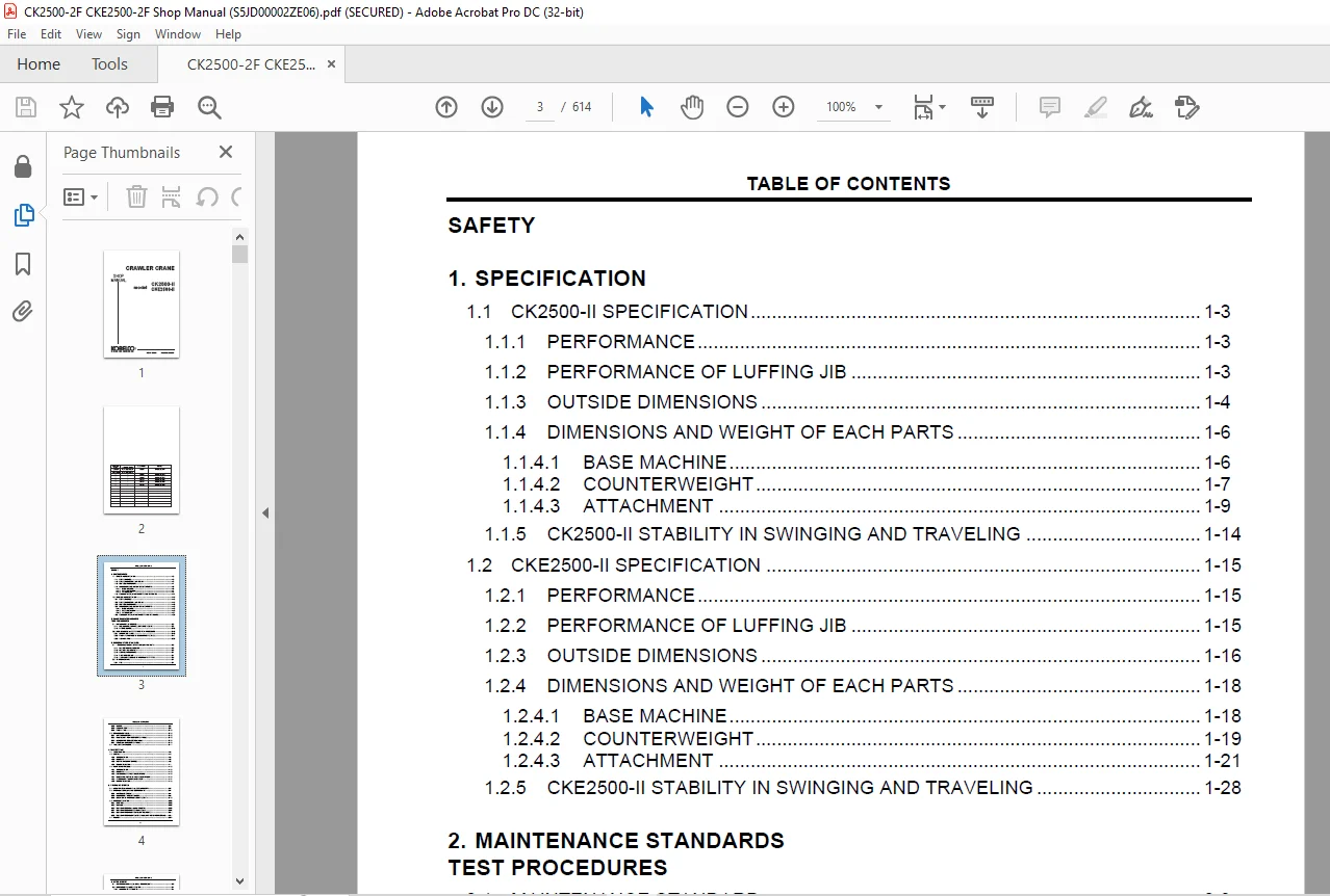
TABLE OF CONTENTS:
Kobelco CRAWLER CRANE CK2500-II CKE2500-II SHOP MANUAL S5JD00002ZE06 – PDF DOWNLOAD
COVER......................................................................................  1
TABLE OF CONTENTS..........................................................................  3
SAFETY..................................................................................... 11
1. SPECIFICATION........................................................................... 41
	1.1 CK2500-II SPECIFICATION............................................................ 43
		1.1.1 PERFORMANCE.................................................................. 43
		1.1.2 PERFORMANCE OF LUFFING JIB................................................... 43
		1.1.3 OUTSIDE DIMENSIONS........................................................... 44
		1.1.4 DIMENSIONS AND WEIGHT OF EACH PARTS.......................................... 46
		1.1.5 CK2500-II STABILITY IN SWINGING AND TRAVELING................................ 54
	1.2 CKE2500-II SPECIFICATION........................................................... 55
		1.2.1 PERFORMANCE.................................................................. 55
		1.2.2 PERFORMANCE OF LUFFING JIB................................................... 55
		1.2.3 OUTSIDE DIMENSIONS........................................................... 56
		1.2.4 DIMENSIONS AND WEIGHT OF EACH PARTS.......................................... 58
		1.2.5 CKE2500-II STABILITY IN SWINGING AND TRAVELING............................... 68
2. MAINTENANCE STANDARDS
TEST PROCEDURES................................................... 69
	2.1 MAINTENANCE STANDARD............................................................... 71
		2.1.1 PIN, BUSHING, SPRING, LINING AND SHEAVE...................................... 71
		2.1.2 PROPEL DEVICE................................................................ 78
	2.2 PERFORMANCE STANDARD AND TEST PROCEDURE............................................ 84
		2.2.1 OPERATING SPEED.............................................................. 84
		2.2.2 POINT AND METHOD OF MEASURING PRESSURE....................................... 85
		2.2.3 SLEWING RING................................................................. 91
3. GENERAL WORK STANDARD................................................................... 93
	3.1 TIGHTENING TORQUE OF CAPSCREWS AND NUTS............................................ 95
		3.1.1 METRIC COARSE THREADS........................................................ 95
		3.1.2 METRIC FINE THREADS.......................................................... 95
		3.1.3 COARSE THREDS UNC............................................................ 96
		3.1.4 FINE THREADS UNF............................................................. 96
		3.1.5 TIGHTENING TORQUE OF HYDRAULIC FITTINGS...................................... 97
	3.2 STANDARD PARTS..................................................................... 99
		3.2.1 BOLT......................................................................... 99
		3.2.2 O-RING.......................................................................100
		3.2.3 BACK-UP RING.................................................................101
		3.2.4 BITE FITTING.................................................................102
	3.3 CONVERSION TABLE...................................................................104
		3.3.1 UNIT CONVERSION..............................................................104
		3.3.2 MILLIMETER : INCH CONVERSION TABLE...........................................105
		3.3.3 METER-FOOT CONVERSION TABLE..................................................107
		3.3.4 GRADIENT CONVERSION TABLE....................................................108
	3.4 TABLE OF UNIT WEIGHT...............................................................109
4. POWER TRAIN.............................................................................111
	4.1 INTRODUCTION.......................................................................113
	4.2 ENGINE.............................................................................115
		4.2.1 INTRODUCTION.................................................................115
		4.2.2 REMOVAL......................................................................115
		4.2.3 REPAIR AND MAINTENANCE.......................................................116
		4.2.4 RE-INSTALLATION..............................................................117
	4.3 PUMP DRIVE ASSEMBLY................................................................120
		4.3.1 INTRODUCTION.................................................................120
		4.3.2 REMOVAL......................................................................120
		4.3.3 DISASSEMBLING THE POWER DIVIDER..............................................122
		4.3.4 CHECK AND REPAIR OF THE POWER DIVIDER........................................123
		4.3.5 ASSEMBLING THE POWER DIVIDER.................................................124
		4.3.6 RE-INSTALLATION..............................................................125
5. HYDRAULIC SYSTEM........................................................................131
	5.1 LOCATION OF MAIN HYDRAULIC COMPONENTS..............................................133
	5.2 HYDRAULIC CIRCUITS AND COMPONENTS..................................................134
		5.2.1 HYDRAULIC CIRCUIT............................................................134
		5.2.2 COMPONENT SPECIFICATIONS.....................................................138
		5.2.3 LOCATION OF HYDRAULIC COMPONENTS.............................................142
	5.3 HYDRAULIC SYSTEM...................................................................150
		5.3.1 PREFACE......................................................................150
		5.3.2 OUTLINE......................................................................150
		5.3.3 OIL FLOW FROM No.1 and No. 2 PUMPS...........................................152
		5.3.4 OIL FLOW FROM No.3 AND No.4 PUMPS............................................154
		5.3.5 OIL FLOW FROM No.5 PUMP (CONTROL PUMP).......................................157
		5.3.6 OIL FLOW FROM No.6 PUMP (FOR AUXILIARY ACTUATOR CIRCUIT).....................161
	5.4 VALVES.............................................................................164
6. HOIST SYSTEM............................................................................171
	6.1 APPARATUS AND LOCATION OF COMPONENTS...............................................173
	6.2 CONSTRUCTION AND FUNCTION..........................................................174
		6.2.1 HYDRAULIC SCHEMATIC..........................................................174
		6.2.2 LIFTING A LOAD...............................................................176
		6.2.3 HOLDING A RAISED LOAD........................................................178
		6.2.4 LOWERING A LOAD (POWERED LOWERING)...........................................180
		6.2.5 FREE FALL OPERATION..........................................................183
		6.2.6 FREE FALL ACCELERATION.......................................................186
	6.3 DRUM LOCK..........................................................................188
		6.3.1 ASEEMBLY DRAWING.............................................................188
		6.3.2 ADJUSTMENT OF DRUM LOCK......................................................189
	6.4 WINCH ASSEMBLY.....................................................................190
		6.4.1 WINCH INSTAL.................................................................190
		6.4.2 WINCH ASSEMBLY / REDUCTION UNIT WITHOUT FREE FALL (STD.).....................191
		6.4.3 WINCH ASSEMBLY WITH FREE FALL (OPT.).........................................193
	6.5 BRAKE PEDAL........................................................................194
		6.5.1 ASSEMBLY DRAWING.............................................................194
		6.5.2 ADJUSTING THE BRAKE PEDAL....................................................196
	6.6 BLEEDING AIR FROM BRAKE CIRCUIT....................................................197
7. BOOM HOIST SYSTEM.......................................................................199
	7.1 APPARATUS AND LOCATION OF COMPONENTS...............................................201
	7.2 CONSTRUCTION AND FUNCTION..........................................................203
		7.2.1 HYDRAULIC SCHEMATIC..........................................................203
		7.2.2 RAISING THE BOOM.............................................................204
		7.2.3 NEUTRAL
(MAINTAINING THE BOOM POSITION)......................................206
		7.2.4 LOWERING THE BOOM............................................................208
	7.3 BOOM DRUM LOCK.....................................................................210
		7.3.1 ASSEMBLY DRAWING.............................................................210
		7.3.2 ADJUSTING THE BOOM DRUM LOCK.................................................211
	7.4 DRUM AND REDUCTION UNIT............................................................212
		7.4.1 BOOM WINCH ASSEMBLY..........................................................212
		7.4.2 BOOM DRUM AND REDUCTION UNIT ASSEMBLY........................................213
8. SWING SYSTEM............................................................................215
	8.1 APPARATUS AND LOCATION OF COMPONENTS...............................................217
	8.2 CONSTRUCTION AND FUNCTION..........................................................218
		8.2.1 HYDRAULIC SCHEMATIC..........................................................218
		8.2.2 SWING........................................................................219
		8.2.3 STOPPING.....................................................................223
	8.3 SWING REDUCTION UNIT...............................................................226
	8.4 SWING BEARING......................................................................228
	8.5 SWING LOCK.........................................................................230
9. PROPEL SYSTEM...........................................................................231
	9.1 LOCATION OF THE MAJOR COMPONENTS...................................................233
	9.2 CONSTRUCTION AND FUNCTION..........................................................234
		9.2.1 HYDRAULIC SCHEMATIC..........................................................234
		9.2.2 PROPELLING (RIGHT SIDE FORWARD)..............................................236
		9.2.3 STOPPING.....................................................................238
	9.3 PROPEL REDUCTION UNIT..............................................................240
		9.3.1 REDUCTION UNIT...............................................................242
		9.3.2 MOTOR........................................................................244
	9.4 ADJUSTMENT.........................................................................246
10. ELECTRIC SYSTEM........................................................................247
	10.1 ELECTRICAL WIRING SCHEMATIC.......................................................249
	10.2 CONNECTOR LIST....................................................................263
	10.3 ARRANGEMENT OF ELECTRICAL PART....................................................315
		10.3.1 ELECTRICAL PART OF CAB......................................................315
		10.3.2 ELECTRICAL PART OF RIGHT DECK...............................................319
		10.3.3 ELECTRICAL PART OF FLOOR PLATE & LEFT SIDE STAND PANEL......................323
		10.3.4 ELECTRICAL PART OF REVOLVING FRAME..........................................328
		10.3.5 ELECTRICAL PART OF LEFT DECK................................................330
		10.3.6 ELECTRICAL PART OF LEFT GUARD...............................................336
		10.3.7 HARNESS PART NUMBER LIST (ALL MODELS).......................................337
	10.4 ELECTRICAL PART...................................................................339
		10.4.1 LOCATION AND USE OF FUSE....................................................339
		10.4.2 FUSE BOX (GG73E00004F1).....................................................341
		10.4.3 WIPER CONTROL RELAY(2480U1366)..............................................343
		10.4.4 SWING FLASHER UNIT (2480U306)...............................................344
	10.5 PRESSURE SWITCH...................................................................345
	10.6 PRESSURE SENSOR...................................................................347
	10.7 RELAY BOX (GG24E00024F1)..........................................................349
		10.7.1 ARRANGEMENT OF CONNECTOR....................................................349
		10.7.2 RELAY BOX SCHEMATIC.........................................................351
	10.8 LEFT SIDE STAND PANEL (WITH FREE FALL)............................................354
	10.9 BYPASS SWITCH PANEL...............................................................358
	10.10 TROUBLESHOOTING OF EXHAUST GAS THIRD REGULATION ENGINE...........................359
		10.10.1 FAILURE DIAGNOSIS FUNCTION.................................................359
		10.10.2 HOW TO CHECK THE FAILURE CONTENTS..........................................360
		10.10.3 CHECKING OF DIAGNOSIS LAMP FUNCTION........................................365
		10.10.4 ENGINE ECU.................................................................366
11. LOAD SAFETY DEVICE.....................................................................369
	11.1 PART NAMES AND FUNCTIONS..........................................................371
		11.1.1 FRONT VIEW..................................................................371
		11.1.2 CONFIGURATION OF SCREENS....................................................376
		11.1.3 DATA TRANSMISSION BETWEEN CONTROLLER AND CARDS..............................381
		11.1.4 DETAILS OF INDICATORS ON MAIN DISPLAY SCREEN................................383
		11.1.5 REAR VIEW...................................................................387
		11.1.6 ITEMS REQUIRED TO BE EXECUTED FOR REPLACEMENT OF CONTROLLER OR DATA CARD....392
	11.2 PREPARATION FOR USE...............................................................393
	11.3 TURN THE POWER ON.................................................................394
	11.4 UPGRADING PROGRAMS................................................................395
		11.4.1 PROCEDURES..................................................................395
		11.4.2 UPGRADING OF INDICATION PROGRAMS............................................397
		11.4.3 UPGRADING OF CONTROL PROGRAMS...............................................400
	11.5 STATUS CHECK......................................................................402
		11.5.1 SIGNAL CHECK................................................................403
		11.5.2 OPERATION PROGRESS..........................................................405
		11.5.3 COMMUNICATION DATA..........................................................408
		11.5.4 INDICATION OF ADJUSTMENT VALUE..............................................409
			11.5.4.1 ANGLE SENSOR ADJUSTMENT VALUE.........................................410
			11.5.4.2 LOAD CELL ZERO POINT ADJUSTMENT VALUE.................................411
			11.5.4.3 ADJUSTMENT VALUE OF LOAD CELL FOR LINE-PULL...........................412
			11.5.4.4 RESULT OF MANUFACTURE ADJUSTMENTS "NO LOAD" AND "SOME LOAD"...........413
			11.5.4.5 RESULT OF LOAD ADJUSTMENTS "NO LOAD" AND "SOME LOAD"..................414
			11.5.4.6 ADJUSTMENT VALUE OF WORKING RADIUS....................................415
			11.5.4.7 ALTERATION OF ADJUSTED VALUE..........................................416
			11.5.4.8 DELETION OF ADJUSTED VALUE............................................417
		11.5.5 TROUBLE RECORD..............................................................418
		11.5.6 CHOICE OF LANGUAGE (CKE SERIES ONLY)........................................420
		11.5.7 LOAD RECORD (LOAD RECORD IN THE MAIN MENU)..................................421
	11.6 ADJUSTMENTS.......................................................................422
		11.6.1 REMOVING THE INNER PANEL....................................................422
		11.6.2 ADJUSTMENT..................................................................423
			11.6.2.1 ANGLE SENSOR ADJUSTMENT...............................................426
			11.6.2.2 LOAD CELL ZERO POINT ADJUSTMENT.......................................430
			11.6.2.3 LOAD-LESS ADJUSTMENT & SOME LOAD ADJUSTMENT...........................432
			11.6.2.4 LVL ADJUSTMENT (LVL SETTING)..........................................439
			11.6.2.5 RADIUS ADJUSTMENT.....................................................442
		11.6.3 LOAD ADJUSTMENT.............................................................444
		11.6.4 ADJUSTMENT DATA COPY (INITIALIZATION).......................................447
			11.6.4.1 READING OF THE ADJUSTMENT DATA........................................449
			11.6.4.2 WRITING OF ADJUSTMENT DATA............................................451
			11.6.4.3 INITIALIZATION OF ADJUSTMENT DATA.....................................452
		11.6.5 VERSION CHECK...............................................................453
	11.7 ERROR CODE (ABNORMALITY DETECTION) AND COUNTERMEASURES............................454
	11.8 CONTROL OUTPUT....................................................................458
	11.9 RELEASES..........................................................................470
		11.9.1 RELEASE FUNCTION............................................................470
			11.9.1.1 CRANE RELEASE CHART...................................................470
			11.9.1.2 ALARM SOUND...........................................................476
			11.9.1.3 EXTERNAL INDICATOR LAMPS IN RELEASE CONDITION.........................477
	11.10 MECHANICAL SPECIFICATION.........................................................478
		11.10.1 ENVIRONMENTAL PERFORMANCE PARAMETERS.......................................478
		11.10.2 LOAD CELL (CRANE)..........................................................479
		11.10.3 ANGLE SENSOR...............................................................480
		11.10.4 CONTROLLER.................................................................481
	11.11 EXTERNAL DIMENSIONS..............................................................485
	11.12 ELECTRIC SCHEMATIC DIAGRAM.......................................................486
		11.12.1 CRANE TYPE.................................................................486
		11.12.2 LUFFING TYPE...............................................................487
	11.13 CONTROLLER MALFUNCTION EMERGENCY MEASURES........................................488
	11.14 LOAD SAFETY DEVICE CHECK PROCEDURES..............................................489
12. GAUGE CLUSTER..........................................................................491
	12.1 CONFIGURATION OF DISPLAY..........................................................493
	12.2 PRIORITY..........................................................................494
	12.3 STATUS DISPLAY....................................................................496
	12.4 FAULT LOG DISPLAY.................................................................506
13. TOTAL CONTROLLER.......................................................................511
	13.1 ARRANGEMENT OF TOTAL CONTROLLER...................................................513
	13.2 COMPOSITION OF SYSTEM.............................................................514
		13.2.1 OUTPUT RELATION TO CONTROLLER...............................................515
	13.3 FUNCTION OF TOTAL CONTROLLER......................................................516
	13.4 TOTAL CONTROLLER (HARDWARE).......................................................541
		13.4.1 OUTLINE.....................................................................541
		13.4.2 SPECIFICATIONS OF TOTAL CONTROLLER OUTPUT...................................542
		13.4.3 DETAILS OF TOTAL CONTROLLER CONNECTOR.......................................546
		13.4.4 ARRANGEMENT OF TOTAL CONTROLLER CONNECTOR PIN...............................547
		13.4.5 PROPORTIONAL SOLENOID VALVE MEASURING POSITION (VOLTAGE)....................554
	13.5 ADJUSTMENT OF TOTAL CONTROLLER....................................................556
		13.5.1 NECESSITY OF ADJUSTMENT.....................................................556
		13.5.2 ADJUSTMENT PROCEDURES OF TOTAL CONTROLLER...................................556
	13.6 CONTROLLER MALFUNCTION EMERGENCY MEASURES.........................................563
14. AIR CONDITIONER........................................................................565
	14.1 OPERATION ITEMS...................................................................567
	14.2 SAFETY MONITOR FUNCTIONS..........................................................568
	14.3 DISASSEMBLY AND ASSEMBLY PROCEDURE................................................571
		14.3.1 SPECIAL CONSIDERATIONS DURING REPLACEMENT...................................571
		14.3.2 INTERIOR UNIT...............................................................573
	14.4 OPERATIONAL PRECAUTIONS...........................................................582
	14.5 INSPECTION AND MAINTENANCE........................................................583
		14.5.1 INSPECTION/MAINTENANCE LIST.................................................583
		14.5.2 INSPECTION/MAINTENANCE PROCEDURES...........................................583
	14.6 ELECTRIC SYSTEM SCHEMATIC.........................................................587
15. TRANSLIFTER SYSTEM.....................................................................589
	15.1 LOCATION OF MAIN COMPONENTS.......................................................591
	15.2 CONSTRUCTION AND WORKING PRINCIPLE................................................594
		15.2.1 OUTLINE.....................................................................594
	15.3 WORKING PRINCIPLE.................................................................596
		15.3.1 RAISING THE TRANSLIFTER.....................................................596
		15.3.2 LOWERING THE TRANSLIFTER....................................................598
	15.4 REMOTE CONTROL SWITCH.............................................................600
16. JIB HOIST SYSTEM.......................................................................601
	16.1 APPARATUS AND LOCATION OF COMPONENTS..............................................603
	16.2 CONSTRUCTION AND FUNCTION.........................................................604
		16.2.1 HYDRAULIC SCHEMATIC.........................................................605
		16.2.2 RAISING THE JIB.............................................................606
		16.2.3 NEUTRAL (MAINTAINING THE JIB POSITION)......................................608
		16.2.4 LOWERING THE JIB............................................................610
	16.3 JIB DRUM LOCK.....................................................................612
		16.3.1 ASSEMBLY DRAWING............................................................612
		16.3.2 ADJUSTING THE JIB DRUM LOCK.................................................613
Customer Support: [email protected]
PLEASE NOTE:
- This is the SAME exact manual used by your dealers to fix your vehicle.
- The same can be yours in the next 2-3 mins as you will be directed to the download page immediately after paying for the manual.
- Any queries / doubts regarding your purchase, please feel free to contact [email protected]
S.M