
Koden CVS-841 & CVS-851 Color Sounder Service Manual – PDF Download
Original price was: $65.00.$20.95Current price is: $20.95.
This is the official factory service manual for the Koden CVS-841 & CVS-851 Color Sounder series (CVS-841C/P, CVS-851C/P). It provides complete repair information for qualified technicians, including troubleshooting flowcharts, internal circuit explanations, PCB adjustments, and the full CVS-841/CVS-851 System Test self-diagnosis menu. Essential for service, repair, calibration, and configuration.
Description
Koden CVS-841 & CVS-851 Color Sounder Service Manual – PDF Download
Description
This comprehensive Koden CVS-841 & CVS-851 Color Sounder Service Manual covers the complete service, repair, adjustment, and troubleshooting procedures for the 1 kW (CVS-841C / CVS-851C) and 3 kW (CVS-841P / CVS-851P) fish finder models. Designed for professional marine electronics technicians, this official Koden factory manual provides full circuit-level explanations, diagnostics, adjustments, schematics, and PCB layouts.
Both the C27-700 Main Logic PCB and C29-160 TX/RX Power PCB are documented in depth, with full functional descriptions, test point data, adjustment procedures, and connector pinouts.
🔧 Key Procedures Included
✔ Troubleshooting
Complete CVS-841/CVS-851 troubleshooting flowcharts
“No power,” “No fish finder image,” and “Low sensitivity” diagnostic guides
Fault diagnosis methodology and symptom-based repair routes
✔ Adjustments & Measurements
C29-160 Power PCB: +12V and switching frequency adjustment
TX/RX output power tuning
Noise level & gain calibration
Measuring transmission output
✔ Configuration
S1 DIP switch settings for CVS-841/851
Jumper settings (J1, J2)
Transducer matching table for:
TD-401D
TD-282
TD-504T
Other Koden compatible transducers
Frequency link selection
✔ Diagnostics
Complete System Test Menu:
LCD Test
Key Test
RAM Test
ROM/F-ROM Test
COM Port Test
System configuration data
✔ Schematics & Technical Drawings
Full block diagrams
Interconnection diagrams
Detailed connector pinouts (J2, J3, J5, J6, etc.)
Main Logic PCB (C27-700) schematic
TX/RX PCB (C29-160) schematic
PCB parts layout
Mechanical exploded views
Parts Lists for all sub-assemblies
🗂️ Table of Contents
Chapter 1: General Descriptions
Equipment Outline
Specifications
System Configurations
Transducer Types & Compatibility
Chapter 2: Functional Explanation
Functional Overview
TX/RX Power Circuit (C29-160)
Main Logic Circuit (C27-700)
F-ROM Circuit (C27-720)
Connector Circuit (C29-910)
Front Panel Circuit
Chapter 3: Adjustments and Measurements
Power Supply Adjustments
TX/RX Frequency & Output Settings
Power Output Measurement Procedures
Noise Level Adjustment
System Test Instructions
Chapter 4: Connection to External Devices
External Navigation Equipment
NMEA 0183 Interface
External Sounder Input
Water Temperature & Speed Sensor
Chapter 5: Maintenance
Cleaning
Fuse Replacement
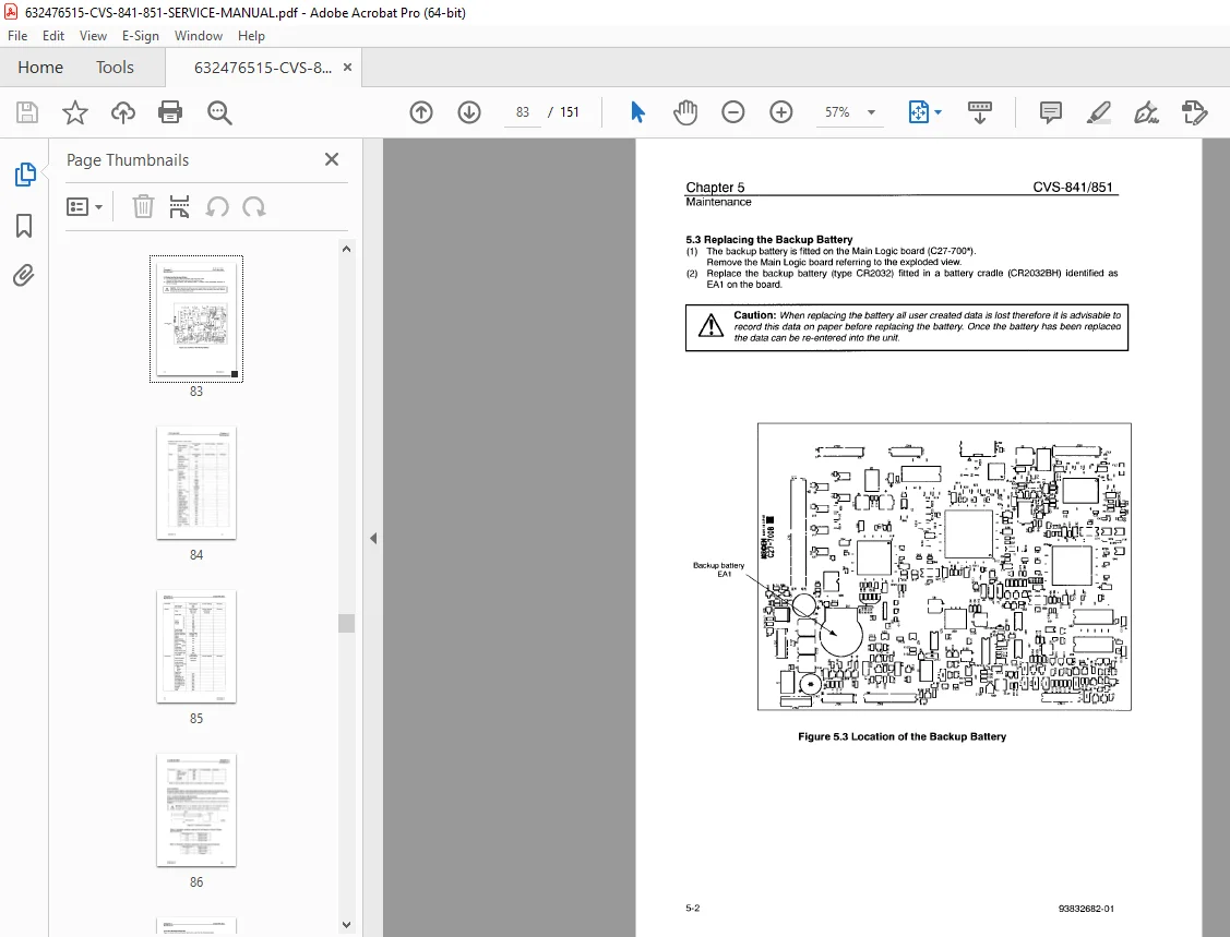
Backup Battery Replacement
Transducer Inspection
Speed/Temperature Sensor Inspection
Chapter 6: Troubleshooting
Fault Diagnosis Method
Complete Troubleshooting Flowcharts
Chapter 7: Technical References
Parts Lists
Circuit Diagrams
PCB Parts Mount Layout
Exploded Assembly Views
📑 File Details
| Field | Details |
|---|---|
| Manual Name | SERVICE MANUAL COLOR SOUNDER CVS-841/851 |
| Models Covered | CVS-841C (1 kW), CVS-841P (3 kW), CVS-851C (1 kW), CVS-851P (3 kW) |
| Year | 2007 (Revision 04 – 07/05/28) |
| Manual PDF Quality | Excellent OEM – Clear, High-Resolution, Searchable |
| Number of Pages | 151 Pages |