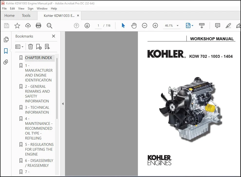
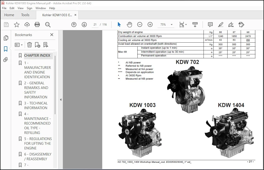
Kohler KDW 702 KDW 1003 KDW 1404 Workshop Manual – PDF DOWNLOAD
Original price was: $75.95.$26.95Current price is: $26.95.
Kohler KDW 702-1003-1404 Workshop Manual – PDF DOWNLOAD
Description
Kohler KDW 702 KDW 1003 KDW 1404 Workshop Manual – PDF DOWNLOAD
FILE DETAILS:
Kohler KDW 702-1003-1404 Workshop Service Repair Manual – PDF DOWNLOAD
Language : English
Pages : 116
Downloadable : Yes
File Type : PDF
Size: 4.58 MB
IMAGES PREVIEW OF THE MANUAL:
Need help? Contact: [email protected]
https://vimeo.com/773719625
DESCRIPTION:
Kohler KDW 702-1003-1404 Workshop Manual – PDF DOWNLOAD
PREFACE:
– Every attempt has been made to present within this service manual, accurate and up to date technical information.
However, development on the KOHLER series is continuous.
Therefore, the information within this manual is subject to change without notice and without obligation.
The materials used by KOHLER to construct the engine’s components undergo strict quality controls and the engine’s
assembly guarantees reliability and long life.
The engine has been built to the machine manufacturer’s specifications, and it was its responsibility to adopt all the measures
needed to meet the essential health and safety requirements as provided for by the laws in force; use of the engine for uses
other than the one defined shall not be considered as compliant with the use intended by KOHLER, who therefore refuses all
responsibility for any injury arising from such an operation.
– The information contained within this service manual is the sole property of KOHLER.
As such, no reproduction or replication in whole or part is allowed without the express written permission of KOHLER.
Information presented within this manual assumes the following:
1 – The person or people performing service work on KOHLER series engines is properly trained and equipped to safely and
professionally perform the subject operation;
2 – The person or people performing service work on KOHLER series engines possesses adequate hand and KOHLER special
tools to safely and professionally perform the subject service operation;
3 – The person or people performing service work on KOHLER series engines has read the pertinent information regarding the
subject service operations and fully understands the operation at hand.
– This manual was written by the manufacturer to provide technical and operating information to authorised KOHLER after-sales
service centres to carry out assembly, disassembly, overhauling, replacement and tuning operations.
– As well as employing good operating techniques and observing the right timing for operations, operators must read the
information very carefully and comply with it scrupulously.
– Time spent reading this information will help to prevent health and safety risks and financial damage.
Written information is accompanied by illustrations in order to facilitate your understanding of every step of the operating phases
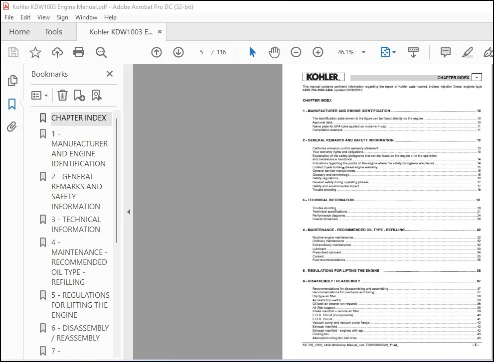
TABLE OF CONTENTS:
Kohler KDW 702-1003-1404 Workshop Manual – PDF DOWNLOAD
1 – MANUFACTURER AND ENGINE IDENTIFICATION…………………………………………………………………………….. 10
The identification plate shown in the figure can be found directly on the engine……………………………………………………..10
Approval data………………………………………………………………………………………………………………………………………………….10
Name plate for EPA rules applied on rocker-arm cap…………………………………………………………………………………………..11
Compilation example……………………………………………………………………………………………………………………………………….11
2 – GENERAL REMARKS AND SAFETY INFORMATION…………………………………………………………………………. 12
California emission control warranty statement…………………………………………………………………………………………………..13
Your warranty rights and obligations………………………………………………………………………………………………………………….13
Explanation of the safety pictograms that can be found on the engine or in the operation
and maintenance handbook……………………………………………………………………………………………………………………………..14
Indications regarding the points on the engine where the safety pictograms are placed…………………………………………..14
Limited 3 year kohler® diesel engine warranty……………………………………………………………………………………………………15
General service manual notes………………………………………………………………………………………………………………………….15
Glossary and terminology………………………………………………………………………………………………………………………………..15
Safety regulations……………………………………………………………………………………………………………………………………………16
General safety during operating phases…………………………………………………………………………………………………………….17
Safety and environmental impact ……………………………………………………………………………………………………………………..17
Trouble shooting……………………………………………………………………………………………………………………………………………..18
3 – TECHNICAL INFORMATION………………………………………………………………………………………………………………18
Trouble shooting……………………………………………………………………………………………………………………………………………..18
Techinical specifications…………………………………………………………………………………………………………………………………..21
Performance diagrams…………………………………………………………………………………………………………………………………… 24
Overall dimension………………………………………………………………………………………………………………………………………….. 28
4 – MAINTENANCE – RECOMMENDED OIL TYPE – REFILLING……………………………………………………………….. 32
Routine engine maintenance…………………………………………………………………………………………………………………………… 32
Ordinary maintenance …………………………………………………………………………………………………………………………………… 32
Extraordinary maintenance ……………………………………………………………………………………………………………………………. 32
Lubricant………………………………………………………………………………………………………………………………………………………. 33
Prescribed lubricant……………………………………………………………………………………………………………………………………….. 34
Coolant………………………………………………………………………………………………………………………………………………………… 35
Fuel recommendations…………………………………………………………………………………………………………………………………… 35
5 – REGULATIONS FOR LIFTING THE ENGINE …………………………………………………………………………………… 36
6 – DISASSEMBLY / REASSEMBLY……………………………………………………………………………………………………….. 37
Recommendations for disassembling and assembling……………………………………………………………………………………….. 37
Recommendations for overhauls and tuning……………………………………………………………………………………………………… 37
Dry type air filter……………………………………………………………………………………………………………………………………………. 38
Air restriction switch………………………………………………………………………………………………………………………………………. 38
Oil bath air cleaner (on request)………………………………………………………………………………………………………………………. 38
Air filter support…………………………………………………………………………………………………………………………………………….. 39
Intake manifold – remote air filter…………………………………………………………………………………………………………………….. 39
E.G.R. Circuit (Components)…………………………………………………………………………………………………………………………… 40
E.G.R. Circuit………………………………………………………………………………………………………………………………………………….41
Vacuum pump and vacuum pump flange……………………………………………………………………………………………………………42
Exhaust manifold…………………………………………………………………………………………………………………………………………….42
Exhaust manifold – engines with egr………………………………………………………………………………………………………………….42
Cooling fan……………………………………………………………………………………………………………………………………………………. 43
Alternator/cooling fan belt drive……………………………………………………………………………………………………………………….. 43
– 6 – KD 702_1003_1404 Workshop Manual_cod. ED0053029340_1° ed_ rev. 00
– Chapter index
Fuel tank (optional)………………………………………………………………………………………………………………………………………… 43
Flywheel………………………………………………………………………………………………………………………………………………………. 44
Return pulley…………………………………………………………………………………………………………………………………………………. 44
Driving pulley………………………………………………………………………………………………………………………………………………… 44
Ringfeder-type rings on kdw 1404……………………………………………………………………………………………………………………. 45
Ringfeder-type rings on kdw 1404 – assembly…………………………………………………………………………………………………… 45
Timing belt cover…………………………………………………………………………………………………………………………………………… 45
Timing belt / timing pulley arrangement……………………………………………………………………………………………………………. 46
Timing belt removal……………………………………………………………………………………………………………………………………….. 46
Tightening pulley……………………………………………………………………………………………………………………………………………. 46
Crankshaft timing pulley…………………………………………………………………………………………………………………………………. 46
Camshaft timing pulley…………………………………………………………………………………………………………………………………….47
Camshaft timing pulley – disassembly/assembly………………………………………………………………………………………………….47
Camshaft timing pulley – reference marks…………………………………………………………………………………………………………..47
Camshaft timing………………………………………………………………………………………………………………………………………………47
Camshaft timing – belt reassembly ……………………………………………………………………………………………………………………47
Camshaft timing – belt tightening tool……………………………………………………………………………………………………………….. 48
Camshaft timing – belt tightening and fastening…………………………………………………………………………………………………. 48
Valve timing check…………………………………………………………………………………………………………………………………………. 48
Valve timing – angles……………………………………………………………………………………………………………………………………… 49
Speed governor…………………………………………………………………………………………………………………………………………….. 50
Speed governor components………………………………………………………………………………………………………………………….. 50
Governor springs…………………………………………………………………………………………………………………………………………… 50
Governor springs for gensets………………………………………………………………………………………………………………………….. 50
Speed governor – limiting speed governor………………………………………………………………………………………………………….51
Speed governor – reassembly…………………………………………………………………………………………………………………………..51
Oil pump………………………………………………………………………………………………………………………………………………………. 52
Oil pump – disassembly………………………………………………………………………………………………………………………………….. 52
Oil pump – reassembly……………………………………………………………………………………………………………………………………. 52
Rocker arm cover………………………………………………………………………………………………………………………………………….. 52
Rocker arm cover gasket………………………………………………………………………………………………………………………………… 53
Crankcase vacuum regulator valve………………………………………………………………………………………………………………….. 53
Crankcase breather……………………………………………………………………………………………………………………………………….. 54
Valve / rocker arm clearance…………………………………………………………………………………………………………………………… 54
Injection pump control rod………………………………………………………………………………………………………………………………. 54
Fuel rail………………………………………………………………………………………………………………………………………………………… 54
Pump/injector unit – non-return valve……………………………………………………………………………………………………………….. 55
Pump/injector unit – disassembly……………………………………………………………………………………………………………………… 55
Rocker arm pivot, dismounting and remounting…………………………………………………………………………………………………. 56
Camshaft, disassembly………………………………………………………………………………………………………………………………….. 56
Camshaft, journal and housing measurement…………………………………………………………………………………………………… 56
Camshaft journals and housings – dimensions (mm)………………………………………………………………………………………….. 57
Camshaft lobe measurement………………………………………………………………………………………………………………………….. 57
Intake / exhaust / injection camshaft lobe height……………………………………………………………………………………………….. 57
Cylinder head, removal…………………………………………………………………………………………………………………………………… 58
Valves………………………………………………………………………………………………………………………………………………………….. 58
Valve stem sealing rings – reassembly……………………………………………………………………………………………………………… 58
Valve springs………………………………………………………………………………………………………………………………………………… 58
Valve, specifications………………………………………………………………………………………………………………………………………. 59
Valve guides and valve guide housings……………………………………………………………………………………………………………. 59
Valve guide insertion……………………………………………………………………………………………………………………………………… 59
Valve seats and housings – dimensions……………………………………………………………………………………………………………. 60
Valve recess and seat sealing width………………………………………………………………………………………………………………… 60
Pre-combustion chamber ………………………………………………………………………………………………………………………………..61
Pre-combustion chamber ring nut removal…………………………………………………………………………………………………………61
Pre-combustion chamber, removal……………………………………………………………………………………………………………………61
Pre-combustion chamber, installation………………………………………………………………………………………………………………..61
Oil pan, removal…………………………………………………………………………………………………………………………………………….. 62
Piston…………………………………………………………………………………………………………………………………………………………… 62
Stop pin rings, dismounting and remounting……………………………………………………………………………………………………… 62
Piston, disassembly and inspection…………………………………………………………………………………………………………………. 63
Piston, class………………………………………………………………………………………………………………………………………………….. 63
Piston, weight……………………………………………………………………………………………………………………………………………….. 64
Piston rings – end gaps (mm)…………………………………………………………………………………………………………………………… 64
Piston ring, clearance between grooves (mm)…………………………………………………………………………………………………… 64
Piston ring, mounting order…………………………………………………………………………………………………………………………….. 65
Piston, assembly……………………………………………………………………………………………………………………………………………. 65
KD 702_1003_1404 Workshop Manual_cod. ED0053029340_1° ed_ – 7 –
Chapter index –
Piston clearance……………………………………………………………………………………………………………………………………………. 65
Head gasket………………………………………………………………………………………………………………………………………………….. 66
Cylinder head assembly…………………………………………………………………………………………………………………………………. 67
Cylinder head tightening procedure KDW 1003…………………………………………………………………………………………………. 67
Cylinder head tightening procedure KDW 1404…………………………………………………………………………………………………. 67
Connecting rod……………………………………………………………………………………………………………………………………………… 68
Big end bearing…………………………………………………………………………………………………………………………………………….. 68
Connecting tod, weight…………………………………………………………………………………………………………………………………… 68
Connecting rod with bearings and pin………………………………………………………………………………………………………………. 68
Connecting rod alignment………………………………………………………………………………………………………………………………. 69
Cylinders………………………………………………………………………………………………………………………………………………………. 69
Cylinder, class………………………………………………………………………………………………………………………………………………. 69
Cylinder roughness………………………………………………………………………………………………………………………………………… 69
Central main bearing caps……………………………………………………………………………………………………………………………… 70
Rear and forward main bearing caps……………………………………………………………………………………………………………….. 70
Check the clearances between the bearings and the journal………………………………………………………………………………. 70
Piston coolant nozzles……………………………………………………………………………………………………………………………………..71
Shoulder half rings…………………………………………………………………………………………………………………………………………..71
Crankshaft axial clearance……………………………………………………………………………………………………………………………….71
Shoulder half rings, oversized elements…………………………………………………………………………………………………………… 72
Crankshaft front and back oil seal rings……………………………………………………………………………………………………………. 72
Crankshaft, lubrication lines……………………………………………………………………………………………………………………………. 73
Crankshaft, check journals and crank………………………………………………………………………………………………………………. 73
Journal and connecting rod pins diameters………………………………………………………………………………………………………. 73
Main bearings and connecting rod big ends diameters………………………………………………………………………………………..74
Clearances between the bearings and corresponding pins…………………………………………………………………………………..74
Hydraulic pump drive……………………………………………………………………………………………………………………………………….75
Third drive, components…………………………………………………………………………………………………………………………………..75
7 – TURBOCHARGER……………………………………………………………………………………………………………………………. 76
Turbo charger…………………………………………………………………………………………………………………………………………………76
Turbocharger components……………………………………………………………………………………………………………………………….76
Turbocharger pressure testing………………………………………………………………………………………………………………………….76
Turbocharger west gate adjustment – regolazione corsa asta comando valvola ” waste gate “………………………………… 77
8 – LUBRIFICATION CIRCUIT………………………………………………………………………………………………………………….78
Lubrification circuit…………………………………………………………………………………………………………………………………………. 78
Internal oil filter and oil sump return pipe………………………………………………………………………………………………………….. 79
Oil pump ……………………………………………………………………………………………………………………………………………………… 79
Oil pump, clearance between rotors………………………………………………………………………………………………………………… 79
Oil pressure regulating valve…………………………………………………………………………………………………………………………… 80
Oil filter cartridge…………………………………………………………………………………………………………………………………………… 80
Oil pressure check…………………………………………………………………………………………………………………………………………. 80
9 – COOLANT CIRCUIT…………………………………………………………………………………………………………………………..82
Coolant circuit……………………………………………………………………………………………………………………………………………….. 82
Radiator and compensation, check and seal tank cap……………………………………………………………………………………….. 83
Coolant circulation pump, components…………………………………………………………………………………………………………….. 83
Thermostatic valve………………………………………………………………………………………………………………………………………… 83
10 – FUEL SYSTEM……………………………………………………………………………………………………………………………….. 84
Fuel feeding / injection circuit …………………………………………………………………………………………………………………………. 84
Fuel filter detached from the tank (on request)………………………………………………………………………………………………….. 84
Fuel lift pump………………………………………………………………………………………………………………………………………………… 84
Fuel pump drive rod projection………………………………………………………………………………………………………………………… 84
Pump/injector unit………………………………………………………………………………………………………………………………………….. 85
Pump/injector unit, components………………………………………………………………………………………………………………………. 85
Plunger barrel ring nut assembly/disassembly…………………………………………………………………………………………………… 86
Injection pump assembly/disassembly……………………………………………………………………………………………………………… 86
Plunger injection pump reassembly…………………………………………………………………………………………………………………. 86
– 8 – KD 702_1003_1404 Workshop Manual_cod. ED0053029340_1° ed_ rev. 00
– Chapter index
Pumping element (old-type injection pump)………………………………………………………………………………………………………. 87
Pumping element…………………………………………………………………………………………………………………………………………… 87
Pump/injector unit se.No. 6590.285 Control data………………………………………………………………………………………………. 87
Injector, setting (old type)……………………………………………………………………………………………………………………………….. 89
Setting of injector according to current pump/injector unit…………………………………………………………………………………… 89
Injector, nozzle projection……………………………………………………………………………………………………………………………….. 89
Injector, spark arrester……………………………………………………………………………………………………………………………………. 89
Injection advance control and regulation………………………………………………………………………………………………………….. 90
Injection advance for currently used pump/injector unit………………………………………………………………………………………. 90
Static injection advance tuning………………………………………………………………………………………………………………………….91
Injection advance references on timing belt protector………………………………………………………………………………………….91
Tdc (top dead center) references………………………………………………………………………………………………………………………91
Tester and special coupling for injection advance control (old-type injection pump)…………………………………………………91
Static injection advance regulation ………………………………………………………………………………………………………………….. 92
Preliminary steps to pump/injector unit delivery balancing test……………………………………………………………………………. 92
Closing the oilhole…………………………………………………………………………………………………………………………………………. 92
Test head b assembly…………………………………………………………………………………………………………………………………….. 92
Instrument connection……………………………………………………………………………………………………………………………………. 93
Injection pumps delivery balancing………………………………………………………………………………………………………………….. 93
Electric control panel with automatic engine stop (Upon request)………………………………………………………………………… 94
11 – ELECTRIC SYSTEM……………………………………………………………………………………………………………………….. 94
Alternator, 14v 33a………………………………………………………………………………………………………………………………………… 95
Alternator, 14v 33a – performance curve………………………………………………………………………………………………………….. 95
Electric starting layout (12v) with alternator 14v 33a………………………………………………………………………………………….. 96
Alternator 14v 45a – 65a………………………………………………………………………………………………………………………………… 97
Alternator, 14v 45a – performance curve………………………………………………………………………………………………………….. 97
Alternator, 14v 65a – performance curve………………………………………………………………………………………………………….. 97
Electric starting layout 12v 33a – 45a – 65a……………………………………………………………………………………………………….. 98
Flywheel alternator………………………………………………………………………………………………………………………………………… 98
Alternator battery charger curve 12v 30a………………………………………………………………………………………………………….. 99
(Two cables at output)……………………………………………………………………………………………………………………………………. 99
Electric starting layout (12v) with flywheel alternator………………………………………………………………………………………… 100
Voltage regulator connections……………………………………………………………………………………………………………………….. 100
Starter motor – bosch dw 12v 1,1 kw……………………………………………………………………………………………………………….101
Starter motor, bosch dw 12v 1,1 kw – performance curve…………………………………………………………………………………..101
Starter motor, bosch 12v 1,6 kw………………………………………………………………………………………………………………………101
Starter motor, bosch dw 12v 1,6 kw – performance curve………………………………………………………………………………….102
Pre-heating glow plug…………………………………………………………………………………………………………………………………….102
Pre-heating plug control unit with coolant temperature sensor……………………………………………………………………………102
Temperature sensor for control unit…………………………………………………………………………………………………………………103
Oil pressure switch (fig. 215)…………………………………………………………………………………………………………………………..103
Pre-heating water temperature thermistor and water temperature indicator thermal contact…………………………………..103
12 – SETTINGS……………………………………………………………………………………………………………………………………. 104
Speed settings…………………………………………………………………………………………………………………………………………….. 104
Setting the idle minimum (standard)……………………………………………………………………………………………………………….. 104
Setting the idle maximum (standard)………………………………………………………………………………………………………………. 104
Pump injection delivery standard setting without dynamometric brake……………………………………………………………….. 104
Injection pump flow limiter and engine torque gearing device……………………………………………………………………………. 105
Pump/injector unit timing with speed governor………………………………………………………………………………………………… 105
Pump/injector unit delivery setting with braked engine……………………………………………………………………………………… 106
E.G.R. Calibration………………………………………………………………………………………………………………………………………….107
13 – STORAGE……………………………………………………………………………………………………………………………………. 108
Engine storage ……………………………………………………………………………………………………………………………………………. 108
Protective treatment…………………………………………………………………………………………………………………………………….. 108
Preparing the engine for operation after protective treatment……………………………………………………………………………. 109
KD 702_1003_1404 Workshop Manual_cod. ED0053029340_1° ed_ – 9 –
Chapter index –
14 – TORQUE SPECIFICATIONS AND USE OF SEALANT………………………………………………………………………110
Table of tightening torques for the main components…………………………………………………………………………………………110
Table of tightening torques for standard screws (coarse thread)…………………………………………………………………………. 111
Table of tightening torques for standard screws (fine thread)……………………………………………………………………………… 111
15 – SPECIAL TOOLS……………………………………………………………………………………………………………………………112
PLEASE NOTE:
- This is not a physical manual but a digital manual – meaning no physical copy will be couriered to you. The manual can be yours in the next 2 mins as once you make the payment, you will be directed to the download page IMMEDIATELY.
- This is the same manual used by the dealers inorder to diagnose your vehicle of its faults.
- Require some other service manual or have any queries: please WRITE to us at [email protected]
S.V