
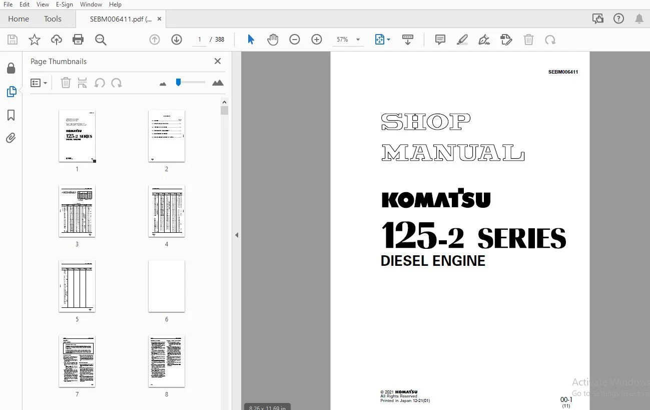
KOMATSU 125-2 SERIES DIESEL ENGINE SHOP MANUAL SEBM006411 – PDF DOWNLOA
$27.95
KOMATSU 125-2 SERIES DIESEL ENGINE SHOP MANUAL SEBM006411 – PDF DOWNLOAD
Description
KOMATSU 125-2 SERIES DIESEL ENGINE SHOP MANUAL SEBM006411 – PDF DOWNLOAD
FILE DETAILS:
KOMATSU 125-2 SERIES DIESEL ENGINE SHOP MANUAL SEBM006411 – PDF DOWNLOAD
Language : English
Pages : 388
Downloadable : Yes
File Type : PDF
IMAGES PREVIEW OF THE MANUAL:
TABLE OF CONTENTS:
KOMATSU 125-2 SERIES DIESEL ENGINE SHOP MANUAL SEBM006411 – PDF DOWNLOAD
COVER.......................................................................................  1
CONTENTS....................................................................................  2
LIST OF REVISED PAGE........................................................................  3
SAFETY......................................................................................  7
	SAFETY NOTICE...........................................................................  7
FOREWORD....................................................................................  9
	GENERAL.................................................................................  9
	HOW TO READ THE SHOP MANUAL............................................................. 10
	HOISTING INSTRUCTIONS................................................................... 11
	METHOD OF DISASSEMBLING, CONNECTING PUSH-PULL TYPE COUPLER.............................. 12
	COATING MATERIALS....................................................................... 14
	STANDARD TIGHTENING TORQUE.............................................................. 16
	ELECTRIC WIRE CODE...................................................................... 19
	CONVERSION TABLE........................................................................ 20
	UNITS................................................................................... 26
01 General.................................................................................. 27
	APPLICABLE MACHINE...................................................................... 28
	SPECIFICATIONS.......................................................................... 30
	GENERAL ASSEMBLY DRAWING................................................................ 40
	ENGINE PERFORMANCE CURVE................................................................ 60
	WEIGHT TABLE............................................................................ 78
11 STRUCTURE AND FUNCTION................................................................... 79
	GENERAL STRUCTURE....................................................................... 80
	INTAKE AND EXHAUST SYSTEM............................................................... 82
		INTAKE AND EXHAUST SYSTEM........................................................... 82
		AIR CLEANER.........................................................................100
		TURBOCHARGER........................................................................102
		AFTERCOOLER.........................................................................105
	ENGINE BODY.............................................................................108
		CYLINDER HEAD.......................................................................108
		CYLINDER BLOCK......................................................................110
		MAIN CIRCULATION PART...............................................................112
		TIMING GEAR.........................................................................114
		VALVE SYSTEM........................................................................116
		FLYWHEEL AND FLYWHEEL HOUSING.......................................................118
	LUBRICATION SYSTEM......................................................................122
		LUBRICATION SYSTEM CHART............................................................122
		OIL PUMP............................................................................124
		REGULATOR VALVE.....................................................................126
		OIL FILTER..........................................................................127
		BYPASS FILTER.......................................................................128
		OIL COOLER..........................................................................129
	FUEL SYSTEM.............................................................................131
		FUEL SYSTEM CHART...................................................................131
		FUEL INJECTION PUMP.................................................................132
		FUEL 2-STAGE SET CONTROL MOTOR MOUNT................................................138
		ENGINE STOP MOTOR, 2-STAGE SET CONTROL MOTOR........................................139
		MAGNETIC SWITCH AND FUEL SOLENOID...................................................144
		BOOST COMPENSATOR...................................................................147
		FUEL INJECTION NOZZLE...............................................................148
		FUEL FILTER.........................................................................149
	COOLING SYSTEM..........................................................................151
		COOLING SYSTEM CHART................................................................151
		WATER PUMP..........................................................................152
		THERMOSTAT..........................................................................154
		CORROSION RESISTOR..................................................................155
		FAN DRIVE...........................................................................156
	ELECTRICAL SYSTEM.......................................................................160
		ALTERNATOR..........................................................................160
		STARTING MOTOR......................................................................165
		ELECTRICAL INTAKE AIR HEATER........................................................168
	ACCESSORY...............................................................................170
		AIR COMPRESSOR......................................................................170
12 TESTING AND ADJUSTING....................................................................173
	ADJUSTING ENGINE SPEED SENSOR...........................................................175
	ENGINE BODY.............................................................................176
		ADJUSTING VALVE CLEARANCE...........................................................176
		MEASURING COMPRESSION PRESSURE......................................................177
	FUEL SYSTEM.............................................................................178
		TESTING AND ADJUSTING FUEL INJECTION TIMING.........................................178
		TESTING AND ADJUSTING FUEL CUT SOLENOID.............................................184
		ADJUSTING ENGINE STOP MOTOR LEVER...................................................185
		FUEL INJECTION PUMP CALIBRATION DATA................................................187
	PERFORMANCE TEST........................................................................218
		RUN-IN STANDARD.....................................................................218
		PERFORMANCE TEST CRITERIA...........................................................222
	TROUBLESHOOTING.........................................................................231
		POINTS TO REMEMBER WHEN TROUBLESHOOTING.............................................233
		METHOD OF USING TROUBLESHOOTING CHART...............................................234
		S-1 Starting performance is poor (Starting always takes time).......................238
		S-2 Engine does not start...........................................................239
			(1) Engine does not turn........................................................239
			(2) Engine turns but no exhaust comes out (Fuel is not being injected)..........240
			(3) Exhaust gas comes out but engine does not start (Fuel is being injected)....241
		S-3 Engine does not pick up smoothly (Follow-up is poor)............................242
		S-4 Engine stops during operations..................................................243
		S-5 Engine does not rotate smoothly (hunting).......................................244
		S-6 Engine lacks output (no power)..................................................245
		S-7 Exhaust smoke is black (incomplete combustion)..................................246
		S-8 Oil consumption is excessive (or exhaust smoke is blue).........................247
		S-9 Oil becomes contaminated quickly................................................248
		S-10 Fuel consumption is excessive..................................................249
		S-11 Oil is in cooling water, or water spurts back, or water level goes down........250
		S-12 Oil pressure caution lamp lights up (drop in oil pressure).....................251
		S-13 Oil level rises................................................................252
		S-14 Water temperature becomes too high (overheating)...............................253
		S-15 Abnormal noise is made.........................................................254
		S-16 Vibration is excessive.........................................................255
	TESTING AND ADJUSTING TOOL LIST.........................................................256
	TESTING AND ADJUSTING DATA..............................................................258
13 DISASSEMBLY AND ASSEMBLY.................................................................271
	DISASSEMBLY.............................................................................271
		SPECIAL TOOL LIST...................................................................272
		1. Starting motor assembly..........................................................273
		2. Engine oil cooler assembly.......................................................273
		3. Setting to tool A1 (overhaul stand)..............................................273
		4. Fan..............................................................................274
		5. Engine mounts....................................................................274
		6. Air cleaner, bracket assembly....................................................274
		7. Turbocharger, exhaust manifold assembly..........................................275
		8. Corrosion resistor and piping, wiring............................................275
		9. Engine oil filter................................................................275
		10. Lubrication valve...............................................................276
		11. Fuel filter.....................................................................276
		12. Fuel injection pipes............................................................276
		13. Aftercooler assembly............................................................276
		14. Fuel injection pump assembly....................................................277
		15. Alternator assembly.............................................................277
		16. Thermostat housing, water pump..................................................278
		17. Fan pulley, drive assembly......................................................278
		18. Front support...................................................................278
		19. Crankshaft pulley, vibration damper.............................................279
		20. Air vent tube, spill pipe.......................................................279
		21. Head covers.....................................................................279
		22. Nozzle holders..................................................................279
		23. Rocker arms.....................................................................280
		24. Crossheads......................................................................280
		25. Push rods.......................................................................280
		26. Rocker arm housings.............................................................280
		27. Cylinder head assemblies........................................................281
		28. Oil pan.........................................................................281
		29. Flywheel........................................................................282
		30. Rear seal.......................................................................282
		31. Flywheel housing................................................................283
		32. Front cover.....................................................................283
		33. Fuel injection pump drive gear..................................................283
		34. Cam follower covers.............................................................284
		35. Cam followers...................................................................284
		36. Camshaft........................................................................284
		37. Oil pump........................................................................285
		38. Idler gear......................................................................285
		39. Oil suction pipe................................................................285
		40. Piston and connecting rod assembly..............................................286
		41. Crankshaft......................................................................287
		42. Piston cooling nozzle...........................................................288
		43. Cylinder liner..................................................................289
	ASSEMBLY................................................................................291
		1. Cylinder liner...................................................................293
		2. Piston cooling nozzle............................................................295
		3. Crankshaft.......................................................................295
		4. Piston and connecting rod assembly...............................................298
		5. Oil suction pipe.................................................................303
		6. Idler gear.......................................................................303
		7. Oil pump.........................................................................303
		8. Camshaft.........................................................................304
		9. Cam followers....................................................................304
		10. Cam follower covers.............................................................304
		11. Drive gear of fuel injection pump...............................................305
		12. Fuel injection pump assembly....................................................306
		13. Adjusting fuel injection timing.................................................307
		14. Front cover.....................................................................308
		15. Crankshaft pulley, vibration damper.............................................308
		16. Flywheel housing................................................................308
		17. Rear seal.......................................................................310
		18. Flywheel........................................................................312
		19. Oil pan.........................................................................314
		20. Cylinder head assemblies........................................................314
		21. Rocker arm housings.............................................................316
		22. Push rods.......................................................................316
		23. Crossheads......................................................................317
		24. Rocker arms.....................................................................317
		25. Adjusting valve clearance.......................................................318
		26. Nozzle holders..................................................................318
		27. Head covers.....................................................................319
		28. Spill pipe, air vent tube.......................................................319
		29. Pulley, front support...........................................................319
		30. Drive sensor, tubes, bracket....................................................320
		31. Water pump, thermostat housing..................................................320
		32. Alternator assembly.............................................................321
		33. Adjusting V-belts...............................................................321
		34. Aftercooler assembly............................................................321
		35. Fuel injection pump pipes.......................................................322
		36. Lubrication valve...............................................................322
		37. Engine oil filter...............................................................323
		38. Corrosion resistor..............................................................323
		39. Turbocharger, exhaust manifold assembly.........................................323
		40. Air cleaner.....................................................................324
		41. Engine mounts...................................................................324
		42. Fan.............................................................................325
		43. Resetting engine in engine stand................................................325
		44. Engine oil cooler assembly......................................................325
		45. Starting motor assembly.........................................................325
		Filling with oil....................................................................325
14 MAINTENANCE STANDARD.....................................................................327
	INTAKE AND EXHAUST SYSTEM...............................................................328
		TURBOCHARGER........................................................................328
	ENGINE BODY.............................................................................330
		CYLINDER HEAD.......................................................................330
		VALVE AND VALVE GUIDE...............................................................332
		ROCKER ARM SHAFT....................................................................334
		CROSSHEAD...........................................................................335
		CYLINDER BLOCK......................................................................336
		CYLINDER LINER......................................................................338
		CRANKSHAFT..........................................................................339
		CAMSHAFT............................................................................340
		CAM FOLLOWER AND PUSH ROD...........................................................341
		TIMING GEAR.........................................................................342
		PISTON, PISTON RING AND PISTON PIN..................................................344
		CONNECTING ROD......................................................................348
		VIBRATION DAMPER....................................................................349
		FLYWHEEL AND FLYWHEEL HOUSING.......................................................350
	COOLING SYSTEM..........................................................................351
		WATER PUMP AND THERMOSTAT...........................................................351
		OIL COOLER..........................................................................352
	LUBRICATION SYSTEM......................................................................353
		OIL PUMP............................................................................353
		MAIN RELIEF VALVE...................................................................354
		REGULATOR VALVE AND SAFETY VALVE....................................................355
	ACCESSORY...............................................................................356
		AIR COMPRESSOR......................................................................356
15 REPAIR AND REPLACEMENTOF PARTS...........................................................357
	REPLACING VALVE SEAT INSERTS............................................................358
	REPLACING NOZZLE HOLDER SLEEVE..........................................................362
	REPLACING VALVE GUIDE...................................................................364
	REPLACING CROSS HEAD GUIDE..............................................................364
	GRINDING THE VALVE......................................................................365
	GRINDING THE FITTING FACE OF CYLINDER HEAD..............................................365
	REPLACING CAM BUSHING...................................................................366
	REPLACING CAM GEAR......................................................................368
	REPLACING FLYWHEEL RING GEAR............................................................368
	PRESSURE TEST...........................................................................369
	REPLACING ENGINE REAR SEAL..............................................................370
	REPLACING CONNECTING ROD SMALL END BUSHING..............................................375
	REPLACING MAIN BEARING CAP..............................................................376
	GRINDING CRANKSHAFT.....................................................................379
	REPLACING WEAR SLEEVE (When equipped with sleeve).......................................388
DESCRIPTION:
KOMATSU 125-2 SERIES DIESEL ENGINE SHOP MANUAL SEBM006411 – PDF DOWNLOAD
1. Before carrying out any greasing or repairs, read all the precautions given on the decals which are fixed to the machine.
2. When carrying out any operation, always wear safety shoes and helmet. Do not wear loose work clothes, or clothes with buttons missing.
• Always wear safety glasses when hitting parts with a hammer.
• Always wear safety glasses when grinding parts with a grinder, etc.
3. If welding repairs are needed, always have a trained, experienced welder carry out the work. When carrying out welding work, always wear welding gloves, apron, hand shield, cap and other clothes suited for welding work.
4. When carrying out any operation with two or more workers, always agree on the operating procedure before starting. Always inform your fellow workers before starting any step of the operation. Before starting work, hang UNDER REPAIR signs on the controls in the operator’s compartment.
5. Keep all tools in good condition and learn the correct way to use them.
6. Decide a place in the repair workshop to keep tools and removed parts. Always keep the tools and parts in their correct places. Always keep the work area clean and make sure that there is no dirt or oil on the floor. Smoke only in the areas provided for smoking. Never smoke while working.
S.S 19/12/24



