Komatsu 12V140E-3 Series Engine Service Manual SEN00291-16 PDF
Original price was: $86.95.$31.95Current price is: $31.95.
Komatsu 12V140E-3 Series Engine Shop Manual SEN00291-16 – PDF DOWNLOAD
Description
Komatsu 12V140E-3 Series Engine Shop Manual SEN00291-16 – PDF DOWNLOAD
FILE DETAILS:
Komatsu 12V140E-3 Series Engine Shop Manual SEN00291-16 – PDF DOWNLOAD
Language : English
Pages : 604
Downloadable : Yes
File Type : PDF
Size: 36.6 MB
IMAGES PREVIEW OF THE MANUAL:
DESCRIPTION:
Komatsu 12V140E-3 Series Engine Shop Manual SEN00291-16 – PDF DOWNLOAD
How to read the shop manual
1. Composition of shop manual
This shop manual contains the necessary technical information for services performed in a workshop.
For ease of understanding, the manual is divided into the following sections.
00. Index and foreword
This section explains the shop manuals list, table of contents, safety, and basic information.
01. Specification
This section explains the specifications of the machine.
10. Structure, function and maintenance standard
This section explains the structure, function, and maintenance standard values of each component.
The structure and function sub-section explains the structure and function of each component. It
serves not only to give an understanding of the structure, but also serves as reference material for
troubleshooting. The maintenance standard sub-section explains the criteria and remedies for disassembly
and service.
20. Standard value table
This section explains the standard values for new machine and judgement criteria for testing,
adjusting, and troubleshooting. This standard value table is used to check the standard values in
testing and adjusting and to judge parts in troubleshooting.
30. Testing and adjusting
This section explains measuring instruments and measuring methods for testing and adjusting, and
method of adjusting each part. The standard values and judgement criteria for testing and adjusting
are explained in Testing and adjusting.
40. Troubleshooting
This section explains how to find out failed parts and how to repair them. The troubleshooting is
divided by failure modes. The S mode of the troubleshooting related to the engine may be also
explained in the Chassis volume and Engine volume. In this case, see the Chassis volume.
50. Disassembly and assembly
This section explains the special tools and procedures for removing, installing, disassembling, and
assembling each component, as well as precautions for them. In addition, tightening torque and
quantity and weight of coating material, oil, grease, and coolant necessary for the work are also
explained.
90. Diagrams and drawings (chassis volume)/Repair and replacement of parts (engine volume)
q Chassis volume
This section gives hydraulic circuit diagrams and electrical circuit diagrams.
q Engine volume
This section explains the method of reproducing, repairing, and replacing parts.
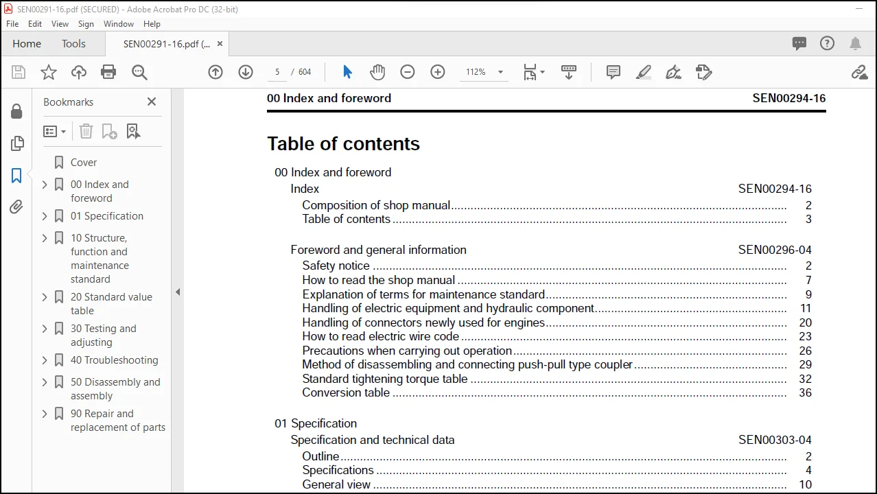
TABLE OF CONTENTS:
Komatsu 12V140E-3 Series Engine Shop Manual SEN00291-16 – PDF DOWNLOAD
Cover………………………………………………………………………….. 1
00 Index and foreword……………………………………………………………. 0
Index………………………………………………………………………. 3
Composition of shop manual………………………………………………… 4
Table of contents………………………………………………………… 5
Foreword and general information………………………………………………. 13
Safety notice……………………………………………………………. 14
How to read the shop manual……………………………………………….. 19
Explanation of terms for maintenance standard……………………………….. 21
Handling of electric equipment and hydraulic component……………………….. 23
Handling of connectors newly used for engines……………………………….. 32
How to read electric wire code…………………………………………….. 35
Precautions when carrying out operation…………………………………….. 38
Method of disassembling and connecting push-pull type coupler…………………. 41
Standard tightening torque table…………………………………………… 44
Conversion table…………………………………………………………. 48
01 Specification………………………………………………………………… 0
Specification and technical data………………………………………………. 55
Outline…………………………………………………………………. 56
Specifications…………………………………………………………… 58
General view…………………………………………………………….. 64
Weight table…………………………………………………………….. 75
Engine performance curves…………………………………………………. 76
10 Structure, function and maintenance standard…………………………………….. 0
Structure, function and maintenance standard, Part 1…………………………….. 83
Air intake and exhaust unit……………………………………………….. 85
Air cleaner……………………………………………………………… 86
Turbocharger…………………………………………………………….. 88
Aftercooler……………………………………………………………… 93
Muffler…………………………………………………………………. 94
Cylinder head……………………………………………………………. 96
Cylinder block……………………………………………………………100
Cylinder liner……………………………………………………………104
Main moving parts…………………………………………………………106
Crankshaft……………………………………………………………….108
Camshaft…………………………………………………………………110
Cam follower and push rod………………………………………………….111
Piston, piston ring, and piston pin…………………………………………112
Connecting rod……………………………………………………………114
Flywheel and flywheel housing………………………………………………116
Vibration damper………………………………………………………….117
Timing gear………………………………………………………………118
Valve system……………………………………………………………..120
Valve and valve guide……………………………………………………..122
Rocker arm and shaft………………………………………………………124
Crosshead and guide……………………………………………………….125
Structure, function and maintenance standard, Part 2……………………………..127
Lubrication system………………………………………………………..130
Lubrication system diagram……………………………………………..130
Oil pump……………………………………………………………..132
Oil cooler……………………………………………………………133
Oil filter……………………………………………………………134
Main relief valve……………………………………………………..135
Oil cooler bypass valve and regulator valve………………………………136
Fuel system………………………………………………………………138
CRI system diagram…………………………………………………….138
CRI system diagram (Poor fuel spec.)…………………………………….140
Outline of CRI system………………………………………………….142
Fuel piping…………………………………………………………..160
Fuel piping (Poor fuel spec.)…………………………………………..165
Fuel filter…………………………………………………………..170
Water separator……………………………………………………….172
Priming pump………………………………………………………….173
Electric priming pump………………………………………………….174
Cooling system……………………………………………………………176
Cooling system diagram…………………………………………………176
Water pump……………………………………………………………178
Thermostat……………………………………………………………180
Corrosion resistor…………………………………………………….181
Cooling fan drive……………………………………………………..183
Electrical equipment………………………………………………………186
Alternator……………………………………………………………186
Starting motor………………………………………………………..189
Starting aid………………………………………………………….191
Engine controller……………………………………………………..194
Engine controller cooler……………………………………………….195
20 Standard value table………………………………………………………….. 0
Standard service value table…………………………………………………..197
Standard service value table……………………………………………….198
Standard service value table for testing, adjusting, and troubleshooting…….198
Running-in standard and performance test standard…………………………203
30 Testing and adjusting…………………………………………………………. 0
Testing and adjusting…………………………………………………………209
Testing and adjusting tools list……………………………………………211
Testing air boost pressure…………………………………………………213
Testing exhaust temperature………………………………………………..214
Adjusting valve clearance………………………………………………….215
Testing compression pressure……………………………………………….217
Testing blow-by pressure…………………………………………………..219
Testing oil pressure………………………………………………………220
Handling fuel system parts…………………………………………………221
Releasing residual pressure in fuel system…………………………………..221
Testing fuel pressure……………………………………………………..222
Reduced cylinder mode operation…………………………………………….223
No-injection cranking……………………………………………………..223
Testing leakage-from pressure limiter and return rate from injector…………….224
Bleeding air from fuel circuit (for D475A-5)…………………………………227
Bleeding air from fuel circuit (for PC2000)………………………………….230
Bleeding air from fuel circuit (Poor fuel spec.)……………………………..232
Testing fuel system for leakage…………………………………………….234
Adjusting speed sensor…………………………………………………….235
Testing and adjusting alternator belt tension………………………………..235
Handling controller high-voltage circuit…………………………………….236
40 Troubleshooting………………………………………………………………. 0
General Information on troubleshooting………………………………………….239
Points to remember when troubleshooting……………………………………..240
Error codes and failure codes list………………………………………….241
Information in troubleshooting table………………………………………..245
Connection table for connector pin numbers…………………………………..247
T- branch box and T- branch adapter table……………………………………283
Troubleshooting of mechanical system (S-mode)……………………………………287
Method of using troubleshooting charts………………………………………289
S-1 Starting performance is poor……………………………………………292
S-2 Engine does not start………………………………………………….293
S-3 Engine does not pick up smoothly………………………………………..296
S-4 Engine stops during operations………………………………………….297
S-5 Engine does not rotate smoothly…………………………………………298
S-6 Engine lacks output (or lacks power)…………………………………….299
S-7 Exhaust smoke is black (incomplete combustion)……………………………301
S-8 Oil consumption is excessive (or exhaust smoke is blue)……………………302
S-9 Oil becomes contaminated quickly………………………………………..303
S-10 Fuel consumption is excessive………………………………………….304
S-11 Oil is in coolant (or coolant spurts back or coolant level goes down)………305
S-12 Oil pressure drops……………………………………………………306
S-13 Oil level rises (Entry of coolant or fuel)………………………………307
S-14 Coolant temperature becomes too high (overheating)……………………….308
S-15 Abnormal noise is made………………………………………………..309
S-16 Vibration is excessive………………………………………………..310
Troubleshooting of electrical system (E-mode), Part 1…………………………….313
E-1 Code [111/CA111] ECM Critical Internal Failure (LH bank)…………………..316
E-2 Code [111/CB111] ECM Critical Internal Failure (RH bank)…………………..318
E-3 Code [115/CA115] Eng. Ne and G (Bkup) Speed Sensor Error (LH bank)………….320
E-4 Code [115/CB115] Eng. Ne and G (Bkup) Speed Sensor Error (RH bank)………….321
E-5 Code [122/CA122] Charge Air Press. Sensor High Error (LH bank only)…………322
E-6 Code [123/CA123] Charge Air Press. Sensor Low Error (LH bank only)………….324
E-7 Code [131/CA131] Throttle Sensor High Error (LH bank only)…………………326
E-8 Code [132/CA132] Throttle Sensor Low Error (LH bank only)………………….327
E-9 Code [135/CA135] Oil Press. Sensor High Error (LH bank only)……………….328
E-10 Code [141/CA141] Oil Press. Sensor Low Error (LH bank only)……………….330
E-11 Code [144/CA144] Coolant Temp. Sensor High Error (LH bank only)……………332
E-12 Code [145/CA145] Coolant Temp. Sensor Low Error (LH bank only)…………….334
E-13 Code [153/CA153] Charge Air Temp. Sensor High Error (LH bank only)…………336
E-14 Code [154/CA154] Charge Air Temp. Sensor Low Error (LH bank only)………….338
E-15 Code [187/CA187] Sensor Sup. 2 Volt. Low Error (LH bank)………………….339
E-16 Code [187/CB187] Sensor Sup. 2 Volt. Low Error (RH bank)………………….339
E-17 Code [212/CA212] Eng. Oil Temp.Sensor High Error (LH bank only)……………340
E-18 Code [213/CA213] Eng. Oil Temp.Sensor Low Error (LH bank only)…………….342
E-19 Code [221/CA221] Ambient Air Press. Sensor High Error (LH bank only)……….344
E-20 Code [222/CA222] Ambient Air Press. Sensor Low Error (LH bank only)………..346
E-21 Code [227/CA227] Sensor Sup. 2 Volt. High Error (LH bank)…………………348
E-22 Code [227/CB227] Sensor Sup. 2 Volt. High Error (RH bank)…………………350
E-23 Code [234/CA234] Eng. Overspeed (LH bank only)…………………………..352
E-24 Code [238/CA238] Ne Speed Sensor Sup. Volt. Error (LH bank)……………….354
E-25 Code [238/CB238] Ne Speed Sensor Sup. Volt. Error (RH bank)……………….356
E-26 Code [263/CA263] Fuel Temp. Sensor High Error (LH bank)…………………..358
E-27 Code [263/CB263] Fuel Temp. Sensor High Error (RH bank)…………………..360
E-28 Code [265/CA265] Fuel Temp. Sensor Low Error (LH bank)……………………362
E-29 Code [265/CB265] Fuel Temp. Sensor Low Error (RH bank)……………………362
E-30 Code [271/CA271] PCV1 Short Error (LH bank)……………………………..364
E-31 Code [271/CB271] PCV1 Short Error (RH bank)……………………………..366
E-32 Code [272/CA272] PCV1 Open Error (LH bank)………………………………368
E-33 Code [272/CB272] PCV1 Open Error (RH bank)………………………………369
E-34 Code [273/CA273] PCV2 Short Error (LH bank)……………………………..370
E-35 Code [273/CB273] PCV2 Short Error (RH bank)……………………………..372
E-36 Code [274/CA274] PCV2 Open Error (LH bank)………………………………374
E-37 Code [274/CB274] PCV2 Open Error (RH bank)………………………………375
E-38 Code [322/CA322] Injector #1 (L/B #1) System Open/Short Error (LH bank)…….376
E-39 Code [323/CA323] Injector #5 (L/B #5) System Open/Short Error (LH bank)…….378
E-40 Code [324/CA324] Injector #3 (L/B #3) System Open/Short Error (LH bank)…….380
E-41 Code [325/CA325] Injector #6 (L/B #6) System Open/Short Error (LH bank)…….382
E-42 Code [331/CA331] Injector #2 (L/B #2) System Open/Short Error (LH bank)…….384
E-43 Code [332/CA332] Injector #4 (L/B #4) System Open/Short Error (LH bank)…….386
E-44 Code [342/CA342] Caribration Code Incompatibility (LH bank)……………….388
E-45 Code [342/CB342] Caribration Code Incompatibility (RH bank)……………….388
E-46 Code [351/CA351] INJ. Drive Circuit Error (LH bank)………………………390
E-47 Code [351/CB351] INJ. Drive Circuit Error (RH bank)………………………392
E-48 Code [352/CA352] Sensor Sup. 1 Volt. Low Error (LH bank)………………….394
E-49 Code [352/CB352] Sensor Sup. 1 Volt. Low Error (RH bank)………………….394
E-50 Code [386/CA386] Sensor Sup. 1 Volt. High Error (LH bank)…………………396
E-51 Code [386/CB386] Sensor Sup. 1 Volt. High Error (RH bank)…………………398
E-52 Code [441/CA441] Battery Voltage Low Error (LH bank)……………………..400
E-53 Code [441/CB441] Battery Voltage Low Error (RH bank)……………………..400
E-54 Code [442/CA442] Battery Voltage High Error (LH bank)…………………….401
E-55 Code [442/CB442] Battery Voltage High Error (RH bank)…………………….401
Troubleshooting of electrical system (E-mode), Part 2…………………………….403
E-56 Code [449/CA449] Rail Press. Very High Error (LH bank)……………………405
E-57 Code [449/CB449] Rail Press. Very High Error (RH bank)……………………405
E-58 Code [451/CA451] Rail Press. Sensor High Error (LH bank)………………….406
E-59 Code [451/CB451] Rail Press. Sensor High Error (RH bank)………………….408
E-60 Code [452/CA452] Rail Press. Sensor Low Error (LH bank)…………………..410
E-61 Code [452/CB452] Rail Press. Sensor Low Error (RH bank)…………………..410
E-62 Code [553/CA553] Rail Press. High Error 1 (LH bank)………………………411
E-63 Code [553/CB553] Rail Press. High Error 1 (RH bank)………………………412
E-64 Code [554/CA554] Rail Press. Sensor In Range Error (LH bank)………………413
E-65 Code [554/CB554] Rail Press. Sensor In Range Error (RH bank)………………413
E-66 Code [559/CA559] Rail Press. Low Error 1 (LH bank)……………………….414
E-67 Code [559/CB559] Rail Press. Low Error 1 (RH bank)……………………….418
E-68 Code [689/CA689] Eng. Ne Speed Sensor Error (LH bank)…………………….422
E-69 Code [689/CB689] Eng. Ne Speed Sensor Error (RH bank)…………………….424
E-70 Code [691/CA691] Intake Air Temp Sensor High Error (LH bank only)………….426
E-71 Code [692/CA692] Intake Air Temp Sensor Low Error (LH bank only)…………..428
E-72 Code [731/CA731] Eng. G (Bkup) Speed Sensor Phase Error (LH bank)………….429
E-73 Code [731/CB731] Eng. G (Bkup) Speed Sensor Phase Error (RH bank)………….429
E-74 Code [757/CA757] All Continuous Data Lost Error (LH bank)…………………430
E-75 Code [757/CB757] All Continuous Data Lost Error (RH bank)…………………430
E-76 Code [778/CA778] Eng. G (Bkup) Speed Sensor Error (LH bank)……………….432
E-77 Code [778/CB778] Eng. G (Bkup) Speed Sensor Error (RH bank)……………….434
E-78 Code [781/CA781] Inter Multi-controller Communication Error (LH bank)………436
E-79 Code [781/CB781] Inter Multi-controller Communication Error (RH bank)………438
E-80 Code [1117/CA1117] Persistent Data Lost Error (LH bank)…………………..439
E-81 Code [1117/CB1117] Persistent Data Lost Error (RH bank)…………………..439
E-82 Code [1257/CA1257] Harness Key error (LH bank)…………………………..440
E-83 Code [1257/CB1257] Harness Key error (RH bank)…………………………..441
E-84 Code [1548/CB1548] Injector #7 (R/B #1) System Open/Short Error (RH bank)…..442
E-85 Code [1549/CB1549] Injector #8 (R/B #2) System Open/Short Error (RH bank)…..444
E-86 Code [1551/CB1551] Injector #10 (R/B #4) System Open/Short Error (RH bank)….446
E-87 Code [1552/CB1552] Injector #11 (R/B #5) System Open/Short Error (RH bank)….448
E-88 Code [1553/CB1553] Injector #12 (R/B #6) System Open/Short Error (RH bank)….450
E-89 Code [1622/CB1622] Injector #9 (R/B #3) System Open/Short Error (RH bank)…..452
E-90 Code [1633/CA1633] KOMNET Datalink Timeout Error (LH bank)………………..454
E-91 Code [2185/CA2185] Throttle Sens. Sup. Volt. High Error (LH bank only)……..456
E-92 Code [2186/CA2186] Throttle Sens. Sup. Volt. Low Error (LH bank only)………458
E-93 Code [2249/CA2249] Rail Press. Very Low Error (LH bank)…………………..459
E-94 Code [2249/CB2249] Rail Press. Very Low Error (RH bank)…………………..459
E-95 Code [- -*1/-] Eng. Overheat (LH bank only)……………………………..460
E-96 Code [- -*2/-] Eng. Oil Press. Low Speed Derate (LH bank only)…………….460
E-97 Code [- -*3/-] Press. Low Torque Derate (LH bank only)……………………461
50 Disassembly and assembly………………………………………………………. 0
General information on disassembly and assembly………………………………….463
How to read this manual……………………………………………………464
Coating materials list…………………………………………………….466
Special tool list…………………………………………………………469
Sketches of special tools………………………………………………….471
Disassembly and assembly, Part 1……………………………………………….475
Disassembly and assembly, Part 1……………………………………………476
General disassembly of engine…………………………………………..476
Disassembly and assembly, Part 2……………………………………………….495
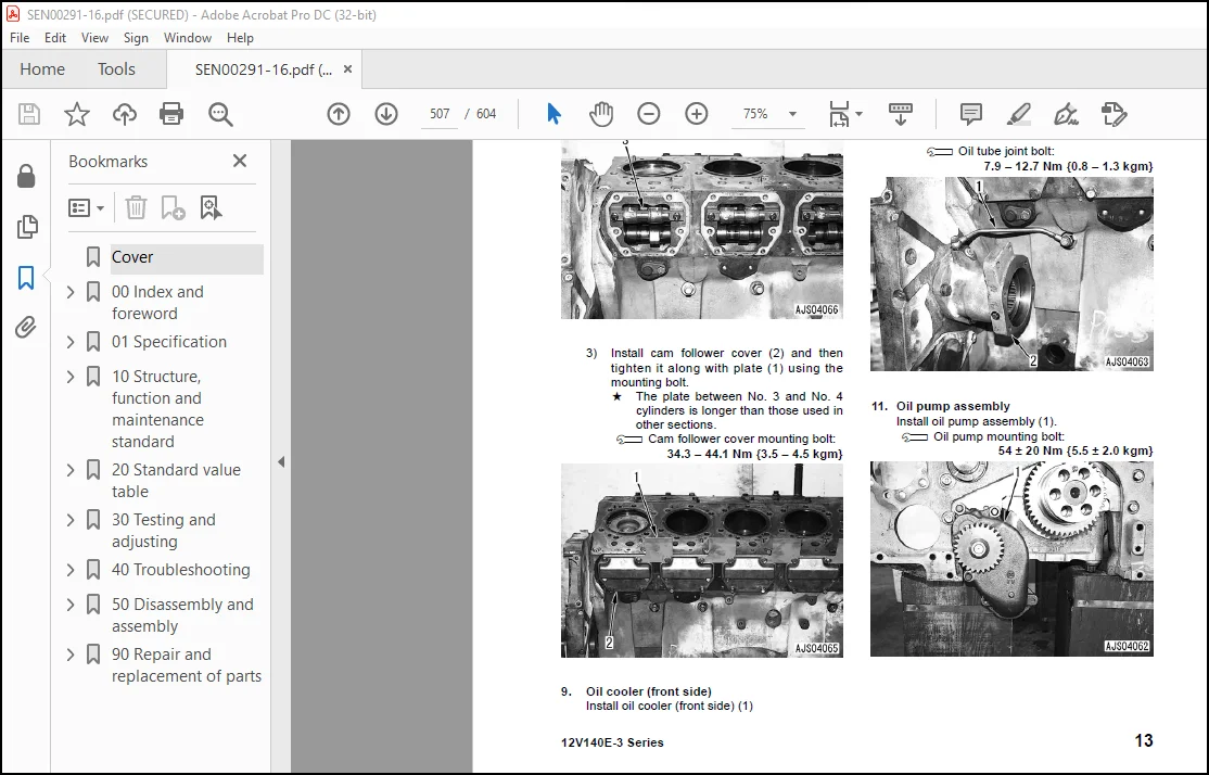
General assembly of engine…………………………………………………496
Disassembly and assembly, Part 3……………………………………………….535
Removal and installation fuel supply pump unit……………………………….536
Removal and installation oil seal unit………………………………………539
90 Repair and replacement of parts………………………………………………… 0
Information related to repair and replacement……………………………………547
Flowchart ……………………………………………………………….548
Special tool table………………………………………………………..550
Parts related to cylinder head…………………………………………………553
Part names related to cylinder head…………………………………………554
Testing and inspection of cylinder head……………………………………..555
Pressure test of cylinder head……………………………………………..557
Replacement of valve guide…………………………………………………557
Replacement of valve seat insert……………………………………………558
Replacement of crosshead guide……………………………………………..565
Repair of cylinder head mounting face by grinding…………………………….566
Repair of valve by grinding………………………………………………..567
Parts related to cylinder block………………………………………………..569
Part names related to cylinder block………………………………………..571
Testing and inspection of cylinder block…………………………………….572
Part names related to crankshaft……………………………………………575
Testing and inspection of crankshaft………………………………………..576
Part names related to connecting rod………………………………………..577
Testing and inspection of connecting rod…………………………………….578
Replacement of flywheel ring gear…………………………………………..579
Replacement of crankshaft gear……………………………………………..580
Replacement of camshaft gear……………………………………………….581
Replacement of main bearing metal cap……………………………………….582
Replacement of connecting rod small end bushing………………………………584
Replacement of cam bushing…………………………………………………585
Repair of cylinder block top by grinding…………………………………….587
Repair of counterbore by grinding…………………………………………..588
Check and identification after repair by grinding…………………………….590
Gasket sealant application procedure………………………………………..591
Repair standard for cylinder liner O-ring……………………………………593
Repair of crankshaft by grinding……………………………………………594
Improvement of surface roughness of crankshaft journal………………………..600
Contact us: [email protected]
PLEASE NOTE:
- This is the SAME MANUAL used by the dealerships to diagnose your vehicle
- No waiting for couriers / posts as this is a PDF manual and you can download it within 2 minutes time once you make the payment.
- Your payment is all safe and the delivery of the manual is INSTANT – You will be taken to the DOWNLOAD PAGE.
- So have no hesitations whatsoever and write to us about any queries you may have : heydownloadss @gmail.com
S.V


