
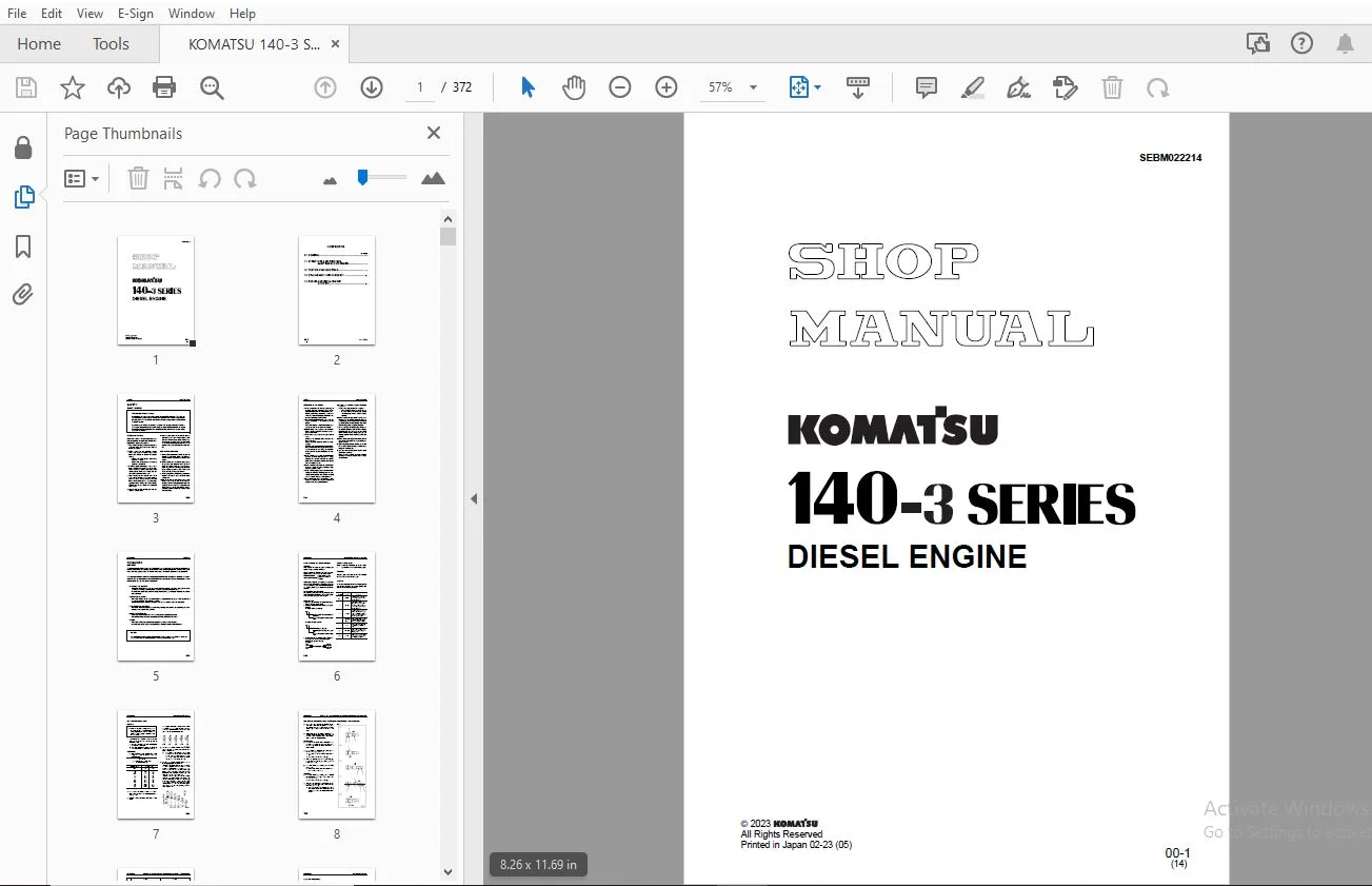
KOMATSU 140-3 Series Diesel Engine Shop Manual SEBM022214 – PDF DOWNLOAD
$27.95
KOMATSU 140-3 Series Diesel Engine Shop Manual SEBM022214 – PDF DOWNLOAD
Description
KOMATSU 140-3 Series Diesel Engine Shop Manual SEBM022214 – PDF DOWNLOAD
FILE DETAILS:
KOMATSU 140-3 Series Diesel Engine Shop Manual SEBM022214 – PDF DOWNLOAD
Language : English
Pages : 372
Downloadable : Yes
File Type : PDF
IMAGES PREVIEW OF THE MANUAL:
TABLE OF CONTENTS:
KOMATSU 140-3 Series Diesel Engine Shop Manual SEBM022214 – PDF DOWNLOAD
140-3 SERIES..........................................................................................................................................  1
	CONTENTS..........................................................................................................................................  2
	01 GENERAL........................................................................................................................................ 23
		OUTLINE....................................................................................................................................... 24
		SPECIFICATIONS................................................................................................................................ 28
		OVERALL DRAWING............................................................................................................................... 34
		WEIGHT TABLE.................................................................................................................................. 42
		ENGINE PERFORMANCE CURVE...................................................................................................................... 44
	11 STRUCTURE AND FUNCTION,MAINTENANCE STANDARD.................................................................................................... 55
		INTAKE, EXHAUST EQUIPMENT..................................................................................................................... 56
		AIR CLEANER................................................................................................................................... 68
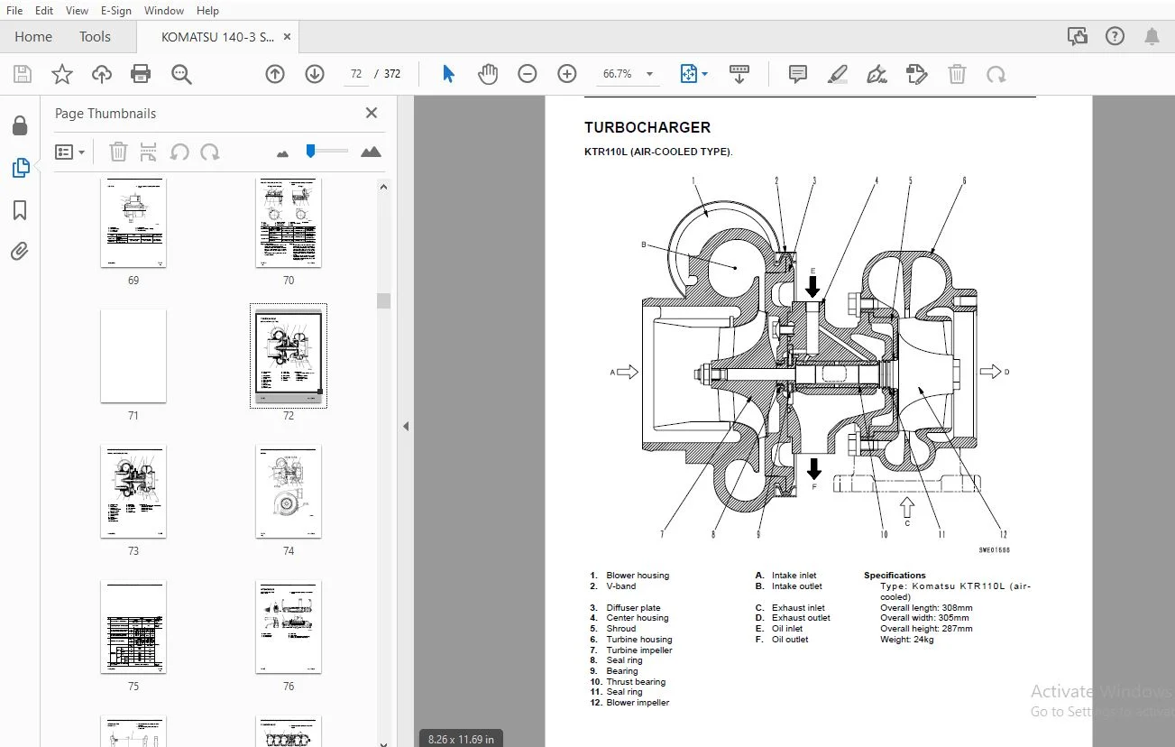
		TURBOCHARGER.................................................................................................................................. 72
		AFTERCOOLER................................................................................................................................... 76
		CYLINDER HEAD................................................................................................................................. 78
		CYLINDER BLOCK................................................................................................................................ 82
		CYLINDER LINER................................................................................................................................ 85
		MAIN MOVING PARTS............................................................................................................................. 86
		CRANKSHAFT.................................................................................................................................... 88
		CAMSHAFT...................................................................................................................................... 89
		CAM FOLLOWER AND PUSH ROD..................................................................................................................... 90
		PISTON • PISTON RING • PISTON PIN............................................................................................................. 92
		CONNECTING ROD................................................................................................................................ 94
		FLYWHEEL, FLYWHEEL HOUSING.................................................................................................................... 95
		VIBRATION DAMPER.............................................................................................................................. 97
		TIMING GEAR................................................................................................................................... 98
		VALVE SYSTEM..................................................................................................................................102
		VALVE, VALVE GUIDE............................................................................................................................104
		ROCKER ARM AND SHAFT..........................................................................................................................106
		CROSSHEAD AND GUIDE...........................................................................................................................107
		LUBRICATION SYSTEM DIAGRAM....................................................................................................................108
		OIL PUMP......................................................................................................................................109
		OIL FILTER....................................................................................................................................112
		OIL COOLER....................................................................................................................................113
		FUEL SYSTEM DIAGRAM...........................................................................................................................116
		OUTLINE OF CRI SYSTEM.........................................................................................................................117
		FUEL PIPING...................................................................................................................................130
		FUEL COOLER...................................................................................................................................132
		FUEL FILTER...................................................................................................................................133
		COOLING SYSTEM DIAGRAM........................................................................................................................134
		WATER PUMP....................................................................................................................................138
		THERMOSTAT....................................................................................................................................141
		CORROSION RESISTOR............................................................................................................................143
		COOLING FAN DRIVE.............................................................................................................................145
		FRONT PTO.....................................................................................................................................158
		AIR COMPRESSOR................................................................................................................................161
		EXHAUST BRAKE.................................................................................................................................164
		ALTERNATOR....................................................................................................................................169
		STARTING MOTOR................................................................................................................................176
		STARTING AID..................................................................................................................................178
	12 TESTING AND ADJUSTING..........................................................................................................................181
		STANDARD VALUE TABLE FOR TESTING, ADJUSTING,AND TROUBLESHOOTING...............................................................................182
		STANDARD VALUE TABLE FOR ELECTRICAL RELATED PARTS.............................................................................................188
		TOOLS FOR TESTING, ADJUSTING, AND TROUBLESHOOTING.............................................................................................190
		MEASURING INTAKE AIRPRESSURE(BOOST PRESSURE)..................................................................................................191
		MEASURING EXHAUSTTEMPERATURE..................................................................................................................191
		ADJUSTING VALVE CLEARANCE.....................................................................................................................192
		MEASURING COMPRESSION PRESSURE................................................................................................................193
		MEASURING BLOW-BY PRESSURE....................................................................................................................194
		MEASURING OIL PRESSURE........................................................................................................................195
		HANDLING EQUIPMENT INFUEL CIRCUIT.............................................................................................................195
		RELEASING REMAININGPRESSURE IN FUEL SYSTEM....................................................................................................196
		MEASURING FUEL PRESSURE.......................................................................................................................196
		REDUCED CYLINDER MODE OPERATION...............................................................................................................197
		BLEEDING AIR FROM FUEL SYSTEM.................................................................................................................198
		CHECK FOR LEAKAGE IN FUEL SYSTEM..............................................................................................................201
		ADJUSTING SPEED SENSOR........................................................................................................................202
		TESTING AND ADJUSTINGALTERNATOR BELT TENSION..................................................................................................202
		TESTING AND ADJUSTING FAN BELT TENSION........................................................................................................203
		HANDLING CONTROLLER HIGH VOLTAGE CIRCUIT......................................................................................................205
		RUN-IN STANDARD...............................................................................................................................206
		PERFORMANCE TEST STANDARDS....................................................................................................................208
		TROUBLESHOOTING OF ENGINESYSTEM (S MODE)......................................................................................................215
			POINTS TO REMEMBER WHEN TROUBLESHOOTING...................................................................................................216
			METHOD OF USING TROUBLESHOOTING CHARTS....................................................................................................217
			S-1 Starting performance is poor (starting always takes time).............................................................................221
			S-2 Engine does not start.................................................................................................................222
			S-3 Engine does not pick up smoothly (follow-up is poor)..................................................................................225
			S-4 Engine stops during operations........................................................................................................226
			S-5 Engine does not rotate smoothly (hunting).............................................................................................227
			S-6 Engine lacks output (or lacks power)..................................................................................................228
			S-7 Exhaust smoke is black (incomplete combustion)........................................................................................229
			S-8 Oil consumption is excessive (or exhaust smoke is blue)...............................................................................230
			S-9 Oil becomes contaminated quickly......................................................................................................231
			S-10 Fuel consumption is excessive........................................................................................................232
			S-11 Oil is in cooling water (or water spurts back, or water level goes down).............................................................233
			S-12 Oil pressure caution lamp lights up (drop in oil pressure)...........................................................................234
			S-13 Oil level rises (water, fuel in oil).................................................................................................235
			S-14 Water temperature becomes too high (overheating).....................................................................................236
			S-15 Abnormal noise is made...............................................................................................................237
			S-16 Vibration is excessive...............................................................................................................238
		TROUBLESHOOTING OFELECTRICAL SYSTEM (E MODE)..................................................................................................239
			POINTS TO REMEMBER WHEN TROUBLESHOOTING...................................................................................................241
			METHOD OF USING TROUBLESHOOTING FLOWCHART.................................................................................................242
			ERROR CODE DISPLAYS AND POINTS TO REMEMBER WHENTROUBLESHOOTING............................................................................243
			ACTION TAKEN BY CONTROLLER AND CONDITION OFMACHINE WHEN ERROR CODE IS DISPLAYED...........................................................246
			E-1 Error code [E-1b] [Abnormality in NE revolution sensor system]........................................................................255
			E-2 Error code [E-1C] [Abnormality in G revolution sensor system].........................................................................256
			E-3 Error code [E-20] [Abnormality in model selection system].............................................................................257
			E-4 Error code [E-22] [Overrun]...........................................................................................................258
			E-5 Error code [E-23] [Overheat]..........................................................................................................258
			E-6 Error code [E-24] [Drop in oil pressure]..............................................................................................259
			E-7 Error code [E-30] [Abnormality in idling validation signal system]....................................................................260
			E-8 Error code [E-31] [Abnormality in throttle sensor system].............................................................................262
			E-9 Error code [E-34] [Abnormality in water temperature high-temperature sensor system]...................................................265
			E-10 Error code [E-36] [Abnormality in oil pressure switch system]........................................................................266
			E-11 Error code [E-3C] [Abnormality in boost pressure sensor system]......................................................................268
			E-12 Error code [E-3d] [Abnormality in fuel temperature sensor system]....................................................................269
			E-13 Error code [E-50] [Abnormality in preheating relay connecting point system]..........................................................270
			E-14 Error code [E-51] [Abnormality in preheat relay coil system].........................................................................271
			E-15 Error code [E-54] [Short circuit in starting switch C system]........................................................................272
			E-16 Error code [E-56] [Power source system abnormality 1]................................................................................273
			E-17 Error code [E-57] [Power source system abnormality 2]................................................................................275
			E-18 Error code [E-5A] [Abnormality in fuel injection quantity control switch signal].....................................................276
			E-19 Error code [E-6A] [Abnormality in water temperature low-temperature sensor system]...................................................277
			E-20 Error code [E-70] [Excess current in fuel supply pump PCV1 system]...................................................................278
			E-21 Error code [E-71] [Excess current in fuel supply pump PCV2 system]...................................................................279
			E-22 Error code [E-74] [Disconnection in fuel supply pump PCV1 system]....................................................................280
			E-23 Error code [E-75] [Disconnection in fuel supply pump PCV2 system]....................................................................281
			E-24 Error code [E-77] [Abnormality in common rail fuel pressure sensor system]...........................................................282
			E-25 Error code [E-79] [Common rail fuel high pressure abnormality 1] Error code [E-7A] [Common rail fuel high pressure abnormality 2]....283
			E-26 Error code [E-7b] [Fuel supply pump non-force feed 1] Error code [E-7C] [Fuel supply pump non-force feed 2]..........................284
			E-27 Error code [E-7d] [Abnormality in common rail fuel pressure].........................................................................286
			E-28 Error code [E-80] [Defective controller].............................................................................................286
			E-29 Error code [E-81] [Disconnection in No. 1 fuel injector system]......................................................................287
			E-30 Error code [E-82] [Disconnection in No. 2 fuel injector system]......................................................................288
			E-31 Error code [E-83] [Disconnection in No. 3 fuel injector system]......................................................................289
			E-32 Error code [E-84] [Disconnection in No. 4 fuel injector system]......................................................................290
			E-33 Error code [E-85] [Disconnection in No. 5 fuel injector system]......................................................................291
			E-34 Error code [E-86] [Disconnection in No. 6 fuel injector system]......................................................................292
			E-35 Error code [E-8A] [Short circuit in No. 1, No. 2, No. 3 fuel injector system]........................................................293
			E-36 Error code [E-8b] [Short circuit in No. 4, No. 5, No. 6 fuel injector system]........................................................296
	13 DISASSEMBLY AND ASSEMBLY.......................................................................................................................299
		METHOD OF USING MANUAL........................................................................................................................300
		PRECAUTIONS WHEN CARRYING OUT OPERATION.......................................................................................................301
		SPECIAL TOOL LIST.............................................................................................................................303
		GENERAL DISASSEMBLY OF ENGINE.................................................................................................................304
		GENERAL ASSEMBLY OF ENGINE....................................................................................................................320
		PROCEDURE FOR REMOVING AND INSTALLING FUEL SUPPLYPUMP UNIT....................................................................................352
	15 REPAIR AND REPLACEMENTOF PARTS.................................................................................................................355
		GRINDING OF FITTING FACE OF CYLINDER HEAD.....................................................................................................356
		REPLACING VALVE SEAT INSERT...................................................................................................................357
		PRESSURE TEST.................................................................................................................................362
		REPLACING VALVE GUIDE.........................................................................................................................363
		REPLACING CROSSHEAD GUIDE.....................................................................................................................364
		GRINDING VALVE................................................................................................................................365
		REPLACING CAM BUSHING.........................................................................................................................366
		REPLACING CRANKSHAFT GEAR.....................................................................................................................369
		REPLACING CAM GEAR............................................................................................................................370
		REPLACING FLYWHEEL RING GEAR..................................................................................................................371
		REPLACING CONNECTING ROD SMALL END BUSHING....................................................................................................372
DESCRIPTION:
KOMATSU 140-3 Series Diesel Engine Shop Manual SEBM022214 – PDF DOWNLOAD
This shop manual has been prepared as an aid to improve the quality of repairs by giving the serviceman an accurate understanding of the product and by showing him the correct way to perform repairs and make judgements. Make sure you understand the contents of this manual and use it to full effect at every opportunity.
This shop manual mainly contains the necessary technical information for operations performed in a service workshop. For ease of understanding, the manual is divided into the following chapters; these chapters are further divided into the each main group of components.
STRUCTURE AND FUNCTION
This section explains the structure and function of each component. It serves not only to give an understanding of the structure, but also serves as reference material for troubleshooting.
In addition, this section may contain hydraulic circuit diagrams, electric circuit diagrams, and maintenance standards.
TESTING AND ADJUSTING
This section explains checks to be made before and after performing repairs, as well as adjustments to be made at completion of the checks and repairs. Troubleshooting charts correlating “Problems” with “Causes” are also included in this section.
DISASSEMBLY AND ASSEMBLY
This section explains the procedures for removing, installing, disassembling and assembling each component, as well as precautions for them.
MAINTENANCE STANDARD
This section gives the judgment standards for inspection of disassembled parts. The contents of this section may be described in STRUCTURE AND FUNCTION.
OTHERS
This section mainly gives hydraulic circuit diagrams and electric circuit diagrams. In addition, this section may give the specifications of attachments and options together.
S.S 17/12/24



