Komatsu 140E-6 Series Engine Service Manual SEN05641-03 PDF
Original price was: $86.95.$29.95Current price is: $29.95.
Komatsu 140E-6 Series Engine Shop Manual SEN05641-03 – PDF DOWNLOAD
Description
Komatsu 140E-6 Series Engine Shop Manual SEN05641-03 – PDF DOWNLOAD
FILE DETAILS:
Komatsu 140E-6 Series Engine Shop Manual SEN05641-03 – PDF DOWNLOAD
Language : English
Pages : 316
Downloadable : Yes
File Type : PDF
Size: 17.2 MB
IMAGES PREVIEW OF THE MANUAL:
DESCRIPTION:
Komatsu 140E-6 Series Engine Shop Manual SEN05641-03 – PDF DOWNLOAD
The Komatsu 140E-6 Series Engine Shop Manual (SEN05641-03) is a comprehensive guide to the maintenance, repair, and troubleshooting of the Komatsu 140E-6 engine. This engine is used in a variety of Komatsu machinery, including excavators, dozers, and loaders.
The manual is organized into chapters covering different aspects of the engine, from general information and specifications to disassembly and reassembly procedures. Here is a brief overview of the contents of each chapter:
Chapter 1: General Information and Specifications This chapter provides an introduction to the engine and covers general specifications, including dimensions, weight, and performance characteristics. It also includes a description of the engine control system and the various sensors and switches used to monitor and control engine operation.
Chapter 2: Testing and Adjusting This chapter provides detailed instructions for testing and adjusting the various systems and components of the engine, including the fuel injection system, turbocharger, and cooling system. It also covers procedures for adjusting the valve clearance and timing belt tension.
Chapter 3: Disassembly and Assembly This chapter provides step-by-step instructions for disassembling and reassembling the engine, including the cylinder head, pistons, crankshaft, and other major components. It includes detailed diagrams and illustrations to help guide the reader through the process.
Chapter 4: Troubleshooting This chapter provides a comprehensive guide to troubleshooting engine problems, including diagnostic charts and flowcharts to help identify the source of the problem. It covers common problems such as starting and idling issues, overheating, and loss of power.
Chapter 5: Service Data This chapter provides detailed specifications and service data for the engine, including torque values, fluid capacities, and other critical information.
The manual is written in clear, concise language and includes detailed illustrations and diagrams to help the reader understand the various systems and components of the engine. It is an invaluable resource for anyone involved in the maintenance and repair of Komatsu machinery equipped with the 140E-6 engine.
TABLE OF CONTENTS:
Komatsu 140E-6 Series Engine Shop Manual SEN05641-03 – PDF DOWNLOAD
Cover……………………………………………………………… 1
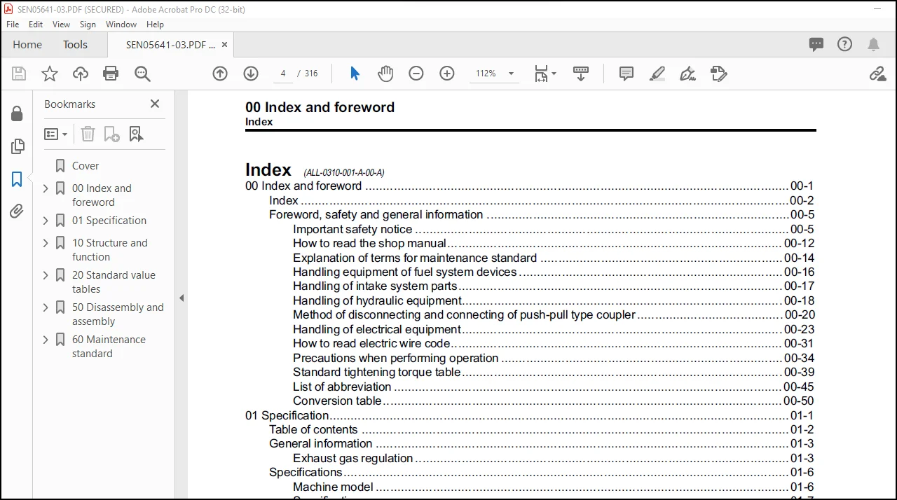
00 Index and foreword ………………………………………………. 3
Index …………………………………………………………. 4
Foreword, safety and general information ………………………….. 7
Important safety notice ……………………………………… 7
How to read the shop manual ………………………………….. 14
Explanation of terms for maintenance standard ………………….. 16
Handling equipment of fuel system devices ……………………… 18
Handling of intake system parts ………………………………. 19
Handling of hydraulic equipment ………………………………. 20
Method of disconnecting and connecting of push-pull type coupler …. 22
Handling of electrical equipment ……………………………… 25
How to read electric wire code ……………………………….. 33
Precautions when performing operation …………………………. 36
Standard tightening torque table ……………………………… 41
List of abbreviation ………………………………………… 47
Conversion table ……………………………………………. 52
01 Specification …………………………………………………… 57
Table of contents ………………………………………………. 58
General information …………………………………………….. 59
Exhaust gas regulation ………………………………………. 59
Specifications …………………………………………………. 62
Machine model ………………………………………………. 62
Specifications ……………………………………………… 63
General view ……………………………………………….. 66
Weight table ……………………………………………….. 79
Engine performance curve …………………………………….. 80
10 Structure and function …………………………………………… 85
Table of contents ………………………………………………. 86
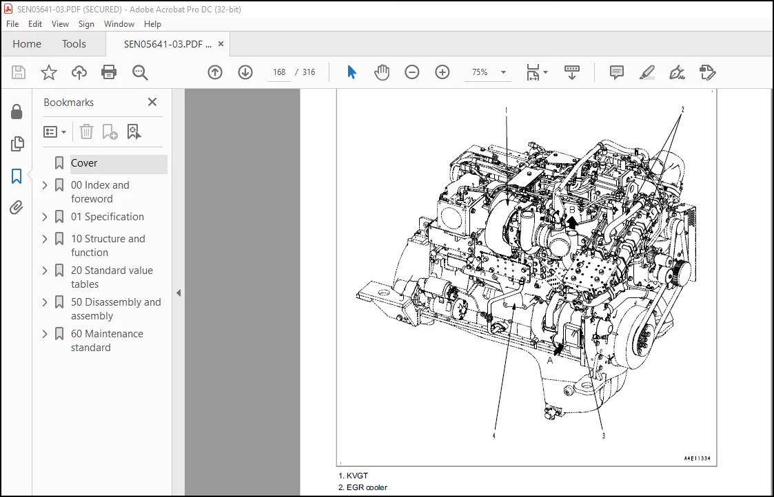
Components layout ………………………………………………. 88
Components layout drawing ……………………………………. 88
Intake and exhaust system parts ………………………………….. 91
Intake and exhaust system layout drawing ………………………. 91
Intake and exhaust system circuit diagram ……………………… 93
Air cleaner ………………………………………………… 95
KVGT ………………………………………………………. 96
Aftercooler …………………………………………………102
EGR system piping drawing …………………………………….103
EGR system circuit diagram ……………………………………105
EGR valve …………………………………………………..106
EGR cooler ………………………………………………….108
Mixing connector …………………………………………….110
KCCV layout drawing ………………………………………….111
KCCV ventilator ……………………………………………..113
KDPF ……………………………………………………….117
Engine main body parts …………………………………………..121
Cylinder head ……………………………………………….121
Cylinder block ………………………………………………123
Main moving parts ……………………………………………125
Timing gear …………………………………………………128
Front cover …………………………………………………129
Valve system ………………………………………………..130
Flywheel and flywheel housing …………………………………132
Lubrication system ………………………………………………133
Lubrication system parts layout drawing ………………………..133
Lubrication system diagram ……………………………………134
Oil pump ……………………………………………………135
Boost oil pump ………………………………………………137
Oil filter ………………………………………………….139
Oil cooler ………………………………………………….140
Oil cooler thermo-valve ………………………………………142
Oil pan …………………………………………………….143
Fuel system …………………………………………………….144
Fuel system parts layout drawing ………………………………144
Fuel system circuit diagram …………………………………..146
Outline of CRI system ……………………………………………149
Fuel system …………………………………………………149
Various controls …………………………………………….150
Structure and operation of CRI system ………………………….152
Structure and operation of component parts ……………………..153
Fuel dozing …………………………………………………….163
Dozing piping drawing ………………………………………..163
Pre-filter ………………………………………………….166
Main filter …………………………………………………167
Cooling system ………………………………………………….168
Cooling system parts layout drawing ……………………………168
Cooling system circuit diagram ………………………………..169
Water pump ………………………………………………….170
Thermostat ………………………………………………….172
Electrical equipment …………………………………………….174
Alternator ………………………………………………….174
Alternator mounting ………………………………………….177
Starting motor ………………………………………………178
Fuel feed pump ………………………………………………180
Fuel feed pump switch ………………………………………..181
Engine wiring harness ………………………………………..182
Engine controller ……………………………………………184
Sensor ……………………………………………………..190
20 Standard value tables …………………………………………….203
Table of contents ……………………………………………….204
Standard service value table ……………………………………..205
Standard value table for engine ……………………………….205
Running-in standard and performance test standard ……………….211
50 Disassembly and assembly ………………………………………….215
Table of contents ……………………………………………….216
Related information on disassembly and assembly …………………….217
How to read this manual ………………………………………217
Coating materials list ……………………………………….219
Special tools list …………………………………………..223
Sketches of special tools …………………………………….225
Disassembly and assembly …………………………………………228
General disassembly of engine …………………………………228
General assembly of engine ……………………………………243
Removal and installation of supply pump ………………………..275
Procedures for replacing engine front oil seal ………………….279
Procedures for replacing engine rear oil seal …………………..282
60 Maintenance standard ……………………………………………..287
Table of contents ……………………………………………….288
Intake and exhaust system parts …………………………………..289
KVGT ……………………………………………………….289
Engine main body parts …………………………………………..290
Cylinder head ……………………………………………….290
Cylinder block ………………………………………………291
Cylinder liner ………………………………………………293
Crankshaft ………………………………………………….294
Cam follower and push rod …………………………………….295
Piston ……………………………………………………..296
Connecting rod ………………………………………………298
Timing gear …………………………………………………300
Camshaft ……………………………………………………302
Valve and valve guide ………………………………………..303
Rocker arm ………………………………………………….305
Crosshead and guide ………………………………………….306
Flywheel ……………………………………………………307
Cooling system ………………………………………………….309
Oil cooler ………………………………………………….309
Water pump ………………………………………………….311
Need help? Contact: [email protected]
https://vimeo.com/799374817
PLEASE NOTE:
- This is the SAME MANUAL used by the dealerships to diagnose your vehicle
- No waiting for couriers / posts as this is a PDF manual and you can download it within 2 minutes time once you make the payment.
- Your payment is all safe and the delivery of the manual is INSTANT – You will be taken to the DOWNLOAD PAGE.
- So have no hesitations whatsoever and write to us about any queries you may have : heydownloadss @gmail.com
S.V


