Komatsu 330M Dump Truck Shop Manual DG728 PDF
$33.95
Komatsu 330M Dump Truck Shop Manual DG728 – PDF DOWNLOAD
SERIAL NUMBERS A10190 – A10211
Description
Komatsu 330M Dump Truck Shop Manual DG728 – PDF DOWNLOAD
FILE DETAILS:
Komatsu 330M Dump Truck Shop Manual DG728 – PDF DOWNLOAD
Language : English
Pages : 895
Downloadable : Yes
File Type : PDF
IMAGES PREVIEW OF THE MANUAL:
DESCRIPTION:
Komatsu 330M Dump Truck Shop Manual DG728 – PDF DOWNLOAD
SERIAL NUMBERS A10190 – A10211
FOREWORD:
- This Manual is written for use by the service technician and is designed to help the technician become
fully knowledgeable of the truck and all its systems in order to keep it running and in production. All
maintenance personnel should read and understand the materials in this manual before performing
maintenance and/or operational checks on the truck. All safety notices, warnings and cautions should
be understood and followed when accomplishing repairs on the truck. - The first section covers component descriptions, truck specifications and safe work practices, as
well as other general information. The major portion of the manual pertains to disassembly, service
and reassembly. Each major serviceable area is dealt with individually. For example: The disassembly,
service and reassembly of the radiator group is discussed as a unit. The same is true of the
engine and engine accessories, and so on through the entire mechanical detail of the truck.
Disassembly should be carried only as far as necessary to accomplish needed repairs. - The illustrations used in this manual are, at times, typical of the component shown and may not
necessarily depict a specific model. - This manual shows dimensioning of U.S. standard and metric (SI) units throughout and all references
to “Right”, “Left”, “Front”, or “Rear” are made with respect to the operator’s normal seated position,
unless specifically stated otherwise. - Standard torque requirements are shown in torque charts in the general information section and
individual torques are provided in the text in bold face type, such as 100 ft.lbs. (135 N.m) torque.
All torque specifications have ±10% tolerance unless otherwise specified. - A Product Identification plate is normally located on the truck frame upright in front of the left side
front wheel and designates the Truck Model Number, Product Identification Number (vehicle serial
number), and Maximum G.V.W. (Gross Vehicle Weight) rating. - The HAULPAK® Model designation consists of three numbers and one letter (i.e. 330M). The three
numbers represent the basic truck model. The letter “M” designates a Mechanical drive and the letter
“E” designates an Electrical propulsion system. - The Product Identification Number (vehicle serial number) contains information which will identify
the original manufacturing bill of material for this unit. This complete number will be necessary for
proper ordering of many service parts and/or warranty consideration. - The Gross Vehicle Weight (GVW) is what determines the load on the drive train, frame, tires, and
other components. The vehicle design and application guidelines are sensitive to the total maximum
Gross Vehicle Weight (GVW) and this means the total weight: the Empty Vehicle Weight + the
fuel & lubricants + the payload.
TABLE OF CONTENTS:
Komatsu 330M Dump Truck Shop Manual DG728 – PDF DOWNLOAD
SERIAL NUMBERS A10190 – A10211
MAIN MENU 0
COVER 1
TABLE OF CONTENTS 5
A – GENERAL INFORMATION 7
MAJOR COMPONENTS & SPECIFICATIONS 9
GENERAL SAFETY 13
WARNINGS & CAUTIONS 43
STANDARD CHARTS & TABLES 51
STANDARD VALUE TABLES 57
B – STRUCTURES 75
GRILLE AND HOOD 77
DECKS 77
LEFT DECK & CAB 78
Removal 78
Installation 78
RIGHT DECK STRUCTURE 79
Removal 79
Installation 79
CENTER DECK STRUCTURE 80
Removal 80
Installation 80
DUMP BODY – REMOVAL 81
DUMP BODY – INSTALLATION 82
BODY PADS 83
Removal 83
Installation 83
Adjustment 83
BODY GUIDE 84
BODY PIN 84
ROCK EJECTORS 85
Rock Ejectors – Inspection 85
FUEL TANK 87
Removal 87
Installation 88
Cleaning 88
VENT 88
QUICK FUEL OPTION 88
C – ENGINE, RADIATOR & AIR CLEANER 89
RADIATOR 91
Removal 91
Service 93
Installation 93
BRAKE OIL COOLER 94
Removal 94
Installation 94
FAN 94
Removal 94
Installation 94
FAN BELT 95
Removal 95
Installation 95
ENGINE 97
Removal 97
Installation 100
DRIVE LINE ADAPTER 101
Removal 101
Installation 102
Repair 103
AIR FILTRATION SYSTEM 105
AIR CLEANER 105
Service Checks 105
Filter Element Replacement 105
MAIN FILTER ELEMENT 107
Main Filter Element Cleaning 107
Air Intake Troubleshooting 108
D – ELECTRICAL SYSTEM 109
24VDC ELECTRICAL SUPPLY SYSTEM 111
Electrical System Description 111
Battery 111
Service 111
Storage 111
Maintenance & Troubleshooting 112
Spillage 113
Battery Charging Alternator 113
Operation 114
Engine Prelube System 115
Design 115
Operation 115
Troubleshooting 117
24VDC ELECTRICAL SYSTEM COMPONENTS 123
Vehicle Monitor System 123
Vehicle Monitor Panel 126
Sensors & Switches 126
Monitor Panel Displays 128
Instrument Panel Indicators, Test Switch 132
Electronic Accelerator Pedal System 134
AISS 135
Transmission Controller 136
POINTS TO REMEMBER WHEN TROUBLESHOOTING 139
POINTS TO REMEMBER WHEN CARRYING OUT MAINTENANCE 140
Points To Remember When Handling Electric Equipment 140
Handling Of Controller Boxes 145
Precautions when performing arc welding on the truck 145
Points to remember when troubleshooting electric circuits 145
Points to remember when handling hydraulic equipment 145
CHECKS BEFORE TROUBLESHOOTING 148
TYPE OF CONNECTOR & POSITION OF INSTALLATION 150
FOR ARSC (AUTOMATIC RETARDER SPEED CONTROL) 155
CONNECTOR PIN ALLOCATION CHART 156
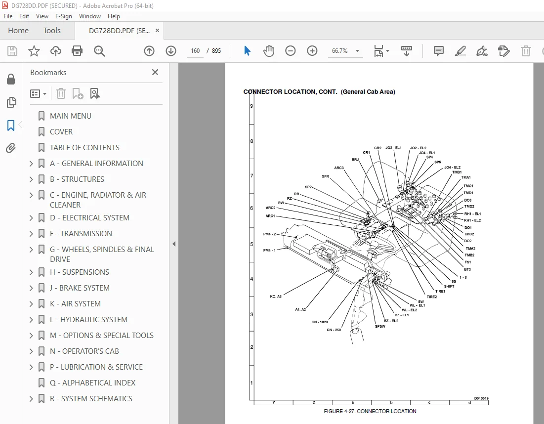
CONNECTION TABLE FOR CONNECTOR PIN NUMBERS 161
EXPLANATIONS OF FUNCTIONS (CONTROL MECHANISM) OF ELECTRICAL SYSTEM 171
Explanation of functions 171
Explanation of self-diagnostic display functions 171
Checking operation of electrical system 173
MONITOR PANEL ACTION CODES & SERVICE MODE 177
Outline 177
Action Code Display 177
Service Mode 178
Method of deleting data from memory 186
Precautions when operating service mode 186
Table 1 Bit Numbers 189
Brake Air Pressure Sensor 190
SELF-DIAGNOSTIC DISPLAY METHOD FOR MONITOR PANEL & CONTROLLERS 191
Monitor Panel 191
Transmission Controller 191
Self-Diagnostic Display Code Table 191
Warning Display Table 192
Method of re-enacting fault displayed 193
Operation of controller when fault is detected 193
Transmission mode display 194
Saving self-diagnostic display to memory 194
Saving service code to memory 195
TABLE OF SERVICE CODES & ACTION CODES 0
Table of service codes & action codes related to monitor panel 196
Table of service codes & action codes related to transmission controller 197
Table of service codes & action codes related to suspension controller 200
Table of service codes & action codes related to PMC 201
METHOD OF USING TABLE 202
METHOD OF USING TROUBLESHOOTING CHARTS 203
Method of using troubleshooting chart for each troubleshooting fault 203
ADJUSTING ELECTRONIC MONITOR (SPEEDOMETER, MODULE) 205
SETTING ROTARY SWITCH (MODEL & NETWORK DATA) WHEN REPLACING TRANSMISSION CONTROLLER 206
METHOD OF DELETING DATA FROM TRANSMISSION CONTROLLER MEMORY 207
TROUBLESHOOTING OF TRANSMISSION CONTROLLER SYSTEM 211
Troubleshooting Charts 211
Troubleshooting Index 211
Points to remember when carrying out troubleshooting of transmission controller system 214
Action taken by self-diagnostic device and problems on the truck 216
Table for transmission controller, transmission related parts 236
A-1 ( u u ) a) (OFF) Controller self-diagnostic display LED does not light up 238
b001(E « 0 1) b) Drop in voltage of controller power source is displayed 239
b0dA(E « d A) c) Drop in voltage of battery direct power source is displayed 240
b0db(E « d b) d) Drop in voltage of main power source is displayed 241
b002(E « 0 2) e) Fault in transmission cut relay power source is displayed 242
A-2 b003(E « 0 3) Fault in neutral safety circuit is displayed 243
A-3 b005(E « 0 5) Double engagement for clutch is displayed 244
A-4 b006(E « 0 6) Fault in transmission (cut relay) is displayed 245
A-5 b008(E « 0 8) Fault in rear brake solenoid is displayed 246
A-6 b009(E « 0 9) Fault in exhaust brake solenoid is displayed 247
A-7 b0C4(E « C 4) a) Short circuit with ground in BCV rear solenoid is displayed 248
b0C6(E « C 6) b) Short circuit in BCV rear solenoid is displayed 248
b0C8(E « C 8) c) Disconnection in BCV rear solenoid is displayed 250
A-8 b010(E « 1 0) or b060 (E « 6 0) 251
b011(E « 1 1) or b061 (E « 6 1) 252
b012(E « 1 2) or (E « 6 2) 253
b013(E « 1 3) or (E « 6 3) 254
A-9 b022(E « 2 2) or b023 (E « 2 3) 255
b024(E « 2 4) or b028 (E « 2 8) 256
A-10 b014(E « 1 4) a) Fault in model selection (wiring harness) is displayed 257
b0A1(E « A 1) b) Fault in model selection (rotary switch) is displayed 258
A-11b007(E « 0 7) a) Short circuit in shift lever assembly power source is displayed 259
b015(E « 1 5) b) Shift lever position signal input for 2 or more circuit is displayed 260
b016(E « 1 6) c) Shift lever position signal is not inputted 262
A-12 b017(E « 1 7) Fault in accelerator signal is displayed 264
A-13b019(E « 1 9) Fault in transmission oil temperature sensor is displayed 265
A-14b032(E « 3 2) – b038 (E « 3 8) 266
b042(E « 4 2) – b048 (E « 4 8) 268
b-1) Checking fill signal 268
b042(E « 4 2) – b043 (E « 4 3) 269
b044(E « 4 4) – b048 (E « 4 8) 269
A-15b052(E « 5 2) – b058 (E « 5 8) 270
A-16b071(E « 7 1) – b078 (E « 7 8) 271
b091(E « 9 1) – b098 (E « 9 8) 271
A-17b0A2(E « A 2) a) Fault in torque converter oil temperature sensor is displayed 273
b0A3(E « A 3) b) Fault in fuel level sensor is displayed 274
b0b2(E « b 2) c) Fault in cooling water temperature sensor is displayed 275
b0b3(E « b 3) d) Fault in air pressure sensor is displayed 276
b0b4(E « b 4) e) Fault in retarder brake oil temperature sensor is displayed 277
A-18 b0d1(E « d 1) a) Transmission filter clogged warning is displayed 278
b0d5(E « d 5) b) Tilt warning is displayed 279
b0d6(E « d 6) c) Drop in radiator water level warning is displayed 280
b0d7(E « d 7) d) Battery charge level warning is displayed 281
b0E5(E « E 5) e)Steering oil temperature overheat warning is displayed 282
b0F5(E « F 5) f) Drop in engine oil pressure warning is displayed 283
b0F6(E « F 6) g) Rear brake oil pressure warning is displayed 284
A-19b0B7(E « B 7) Fault in engine oil pressure sensor is displayed 285
A-20b0C1(E « C 1) Fault in connector connection is displayed 286
A-21b0d2(E « d 2) a) Torque converter oil temperature overheat warning is displayed 287
b0d3(E « d 3) b) Engine water temperature overheat warning is displayed 287
b0E9(E « E 9) c) Air pressure drop warning is displayed 287
b0F3(E « F 3) d) Retarder brake oil temperature overheat warning is displayed 287
b0d8(E « d 8) e) Engine overrun actuated is displayed 288
b0d9(E « d 9) f) Engine overshoot actuated is displayed 288
MONITOR PANEL TROUBLESHOOTING 289
TROUBLESHOOTING CHARTS 289
TROUBLESHOOTING INDEX 289
Monitor Panel and Controller Self-diagnostic display 291
Action taken by self-diagnostic device and problems on truck (monitor panel) 292
P-1 Check pattern for wiring harnesses between modules 296
P-2 Nothing on monitor panel works 299
P-3 LH, RH module and fuel gauge do not operate 300
P-4 LH, RH module and fuel gauge do not operate 301
P-5 RH module does not operate 302
P-6 LH module does not operate 303
P-7 Odometer does not operate 304
P-8 Service meter display does not operate correctly 305
P-9 Central warning lamp does not operate, or monitor panel detects fault code [A002] 306
P-10 Central warning lamp stays on 307
P-11 Alarm buzzer does not operate, or monitor panel detects failure code A003 308
P-12 Alarm buzzer continues to sound 309
P-13 All data from shift controller (speedometer, tachometer, shift indicator, etc ) are abnormal 310
P-14 Suspension mode power/economy mode displays are abnormal 311
P-15 Gauge displays are abnormal (nothing is displayed, or display does not change) 312
P-16 Cooling water level drop caution lamp does not operate, 313
P-17 Cooling water level drop caution lamp stays on 314
P-18 Emergency steering pilot lamp does not operate, or monitor panel detects service code [A001] 315
P-19 Emergency steering pilot lamp stays on 316
P-20 Engine oil pressure drop caution lamp does not operate 317
P-21 Engine oil pressure drop caution lamp stays on 318
P-22 Exhaust brake pilot lamp does not operate, or monitor panel detects service code [A001] 319
P-23 Exhaust brake pilot lamp (optional) stays on 320
P-24 Charging circuit fault caution lamp does not operate, or monitor panel detects service code [A001 321
P-25 Charging circuit fault caution lamp stays on 322
P-26 Transmission filter clogging caution lamp does not operate 323
P-27 Transmission filter clogging caution lamp stays on 324
P-28 Brake stroke caution lamp does not operate, or monitor panel detects service code [A001] 325
P-29 Brake stroke caution lamp stays on 326
P-30 Preheating switch pilot lamp does not operate, or monitor panel detects service code [A001] 327
P-31 Preheating switch pilot lamp stays on 328
P-32 Tilt warning lamp does not operate, or monitor panel detects service code [A001] 329
P-33 Tilt warning lamp stays on 330
P-34 Body FLOAT (except FLOAT) pilot lamp does not operate, or monitor panel detects service code A001 331
P-35 Body FLOAT (except FLOAT) pilot lamp stays on 332
P-36 Rear brake pilot lamp does not operate, or monitor panel detects service code [A001] 333
P-37 Rear brake pilot lamp stays on 334
P-38 Parking brake pilot lamp does not operate, or monitor panel detects service code [A001] 335
P-39 Parking brake pilot lamp stays on 336
P-40 Maintenance caution lamp does not operate, or monitor panel detects service code [A001] 337
P-41 Maintenance caution lamp stays on 338
P-42 Steering oil temperature caution lamp does not operate, or monitor panel detects service code A001 339
P-43 Steering oil temperature caution lamp stays on 340
P-46 High beam display does not light up 341
P-47 Turn signal lamp (right) does not light up 343
P-48 Turn signal lamp (left) does not light up 344
P-49 Lamp check switch does not operate 345
P-50 AISS switch does not operate 346
P-51 Exhaust brake switch (optional) does not operate 347
P-52 Mode change switch (1) does not operate 348
P-53 Mode change switch (2) does not operate 349
P-54 KPH/MPH speedometer unit selector does not operate 350
P-55 Improper operation of all switch inputs 351
P-56 Monitor panel detects service codes [A014] or [A019] 352
P-58 Monitor panel detects service code [A011 353
P-59 Monitor panel detects service code [A012] 353
P-60 Monitor panel detects service code [A000] 353
ENGINE ELECTRONIC DIAGNOSTIC SYSTEM 355
Fault Code Information (T01-001) 358
ELECTRICAL SPECIFICATIONS 361
HYDRAULIC & MECHANICAL SYSTEMS TROUBLESHOOTING 363
Troubleshooting Index 363
H-1 Truck does not move 364
H-2 Truck does not travel smoothly 366
H-3 Lock-up clutch cannot be disengaged 366
H-4 Excessive shock when starting or shifting 366
H-5 Transmission does not shift up 367
H-6 Truck lacks power or speed when moving 368
H-7 Time lag is excessive when starting to move, or shifting gear 372
H-8 Torque converter oil temperature is high 374
H-9 Torque converter oil pressure is high 375
H-10 Front brakes are ineffective, or effective only on one side 376
H-11 Rear brakes are ineffective, or effective on one side only 377
H-12 Steering wheel is difficult to turn 378
H-13 Steering wheel inoperative 379
H-15 Hoist cylinder lacks lifting force (lifting speed) 380
H-16 Hoist cylinders do not operate 382
H-17 Excessive dump body hydraulic drift 384
H-18 Air pressure does not increase 385
SUSPENSION CONTROLLER SYSTEM TROUBLESHOOTING (OPTIONAL) SP DIAGNOSTIC FLOWCHART 387
SUSPENSION CONTROLLER/SUSPENSION COMPONENTS TROUBLESHOOTING TABLE 388
TRANSMISSION CONTROLLER SYSTEM ELECTRICAL CIRCUIT DIAGRAM 394
SP-1 ALL OFF or Power source fault displayed 396
SP-2 Faulty pressure sensor (right) displayed 397
SP-3 Faulty pressure sensor (left) displayed 398
SP-4 Faulty speed sensor displayed 399
SP-5 Fault in steering sensor displayed 400
SP-6 Defective model selection data displayed 401
SP-7 Fault in solenoid 1 displayed 402
SP-8 Fault in solenoid 2 displayed 403
SP-9 Fault in solenoid 3 displayed 404
SP-10 Disconnection in network displayed 405
SP-11 Defective speed compensation displayed 406
F – TRANSMISSION 407
TORQUE CONVERTER OPERATION 410
Main Relief Valve 415
Torque Converter Relief Valve 415
Lockup Solenoid Valve 417
Testing Hydraulic Pressure of Torque Converter Valve 420
Torque Converter Stall Speed 422
TRANSMISSION OPERATION 423
ECMV (Electronic Control Modulation Valve) 427
TRANSMISSION 438
Removal 438
Installation 440
TRANSMISSION FILTER 442
Service 442
TRANSMISSION OIL COOLER 443
Removal 443
Installation 443
TRANSMISSION OIL STRAINER 443
Removal 443
Installation 443
TORQUE CONVERTER CONTROL VALVE 444
Removal 444
Installation 444
Disassembly 444
Assembly 445
DRIVELINES & U-JOINTS 447
Removal 447
Installation 447
Disassembly 447
Assembly 447
AUTOMATIC SHIFT CONTROL SYSTEM 449
General Information 449
Transmission Shift Controller 449
Power Mode 449
Braking Mode 449
Lock-Up & Engine Overspeed 449
Transmission Speeds Monitoring 449
Self Diagnostics 450
Range Selector Positions & Automatic Gear Shifting Ranges 452
Transmission Operation Modes 452
Automatic Gear Shifting 453
Automatic Shifting Sequence 453
Safety Functions 455
Transmission Range Selector 456
Sensors, Switches 457
Transmission Troubleshooting Procedures 460
G – WHEELS, SPINDLES & FINAL DRIVE 467
TIRES & RIMS 469
General Information 469
FRONT TIRE & RIM 470
Removal 470
Installation 471
REAR TIRE & RIM 471
Removal 471
Installation of rear wheel assembly 472
TIRE MATCHING 474
FRONT WHEEL HUB & SPINDLES 475
FRONT WHEEL HUB 475
Removal 475
FRONT WHEEL BEARING & BRAKE DISC REPLACEMENT 476
FRONT WHEEL HUB INSTALLATION & BEARING ADJUSTMENT 477
A-FRAME 478
Removal 478
Installation 478
CENTER TIE ROD PIVOT 479
Removal 479
Inspection 479
Installation 479
FINAL DRIVE ATTACHMENTS 481
Final Drive Lower Link 481
Pin Removal 481
Pin Installation 482
Bearing Removal & Inspection 482
Bearing Installation 482
Diagonal Panhard Rod 482
Removal 482
Installation 482
Bearing Replacement 483
FINAL DRIVE CENTER CASE ASSEMBLY 485
Specifications 485
Rear Axle 487
Removal 487
Installation 488
DIFFERENTIAL ASSEMBLY 489
Removal 489
Installation 490
Disassembly 490
Disassembly of Pinion Carrier Assembly 491
Differential Gear Unit 492
Disassembly of Differential Gear Unit 492
Assembly of Differential 495
Differential Bearing 495
Assembly of Differential Gear Assembly 495
Installation of Differential Assembly 496
Input Pinion and Carrier Assembly 497
Adjusting Tooth Contact, Backlash 500
FINAL DRIVE PLANETARIES & WHEEL HUBS 503
Final Drive 503
Carrier Assembly 504
Removal 504
Installation 505
Final Drive Carrier 505
Disassembly 505
Assembly 506
Final Drive Assembly 506
Disassembly 506
Assembly 509
H – SUSPENSIONS 511
FRONT SUSPENSION 513
Operation 513
Removal 515
Installation 517
Disassembly 518
Inspection 519
Assembly 519
Attenuation Valve Repair 520
REAR SUSPENSION 521
Operation 521
Removal 522
Installation 523
Disassembly 523
Assembly 524
Spherical Bearing Repair 525
OILING & CHARGING PROCEDURES 527
General 527
Equipment List 527
Front Suspension 527
Front Suspension Oiling 528
Front Suspension Nitrogen Charging 529
Rear Suspension 531
Rear Suspension Oiling 531
Rear Suspension Nitrogen Charging 532
J – BRAKE SYSTEM 535
BRAKE CIRCUIT OPERATION 537
Brake Circuit Operation 537
Component Description 537
Emergency Relay Valve (RE-6) 538
Hand Brake (Retarder) 541
Parking Brake Pilot Valve 543
Parking Brake Relay Valve 544
Brake Chamber (Front) 545
Brake Chamber (Rear) 545
Slack Adjuster 546
Pressure Switch 548
Stop Lamp Switch 548
Parking Brake Switch 549
Automatic Retarder Valve 549
Front Brake Cut-Off Valve 550
Brake Cooling Valve (BCV) 551
Parking & Emergency Brake Valve 552
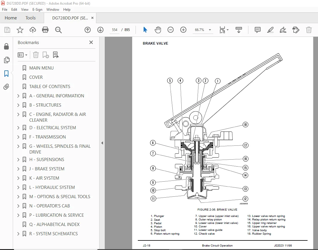
Brake Valve (Treadle) 554
BRAKE CIRCUIT COMPONENT SERVICE 559
Service Brake Treadle Valve 559
Pressure Converters (Front) 562
Pressure Converters (Rear) 566
Slack Adjuster 570
BRAKE CIRCUIT CHECKOUT AND ADJUSTMENT 573
Checking Front Pad Wear 573
Checking Brake Pressure 573
Checking Rear Disc Wear 574
Brake Bleeding 575
Brake Troubleshooting Charts 576
FRONT BRAKES 579
Brake Pads 579
Removal 579
Installation 579
Brake Caliper Assembly 579
Removal 579
Installation 580
Disassembly 580
Inspection Values 580
Assembly 581
REAR BRAKES 583
Removal 583
Installation 584
Disassembly 585
Inspection Values 586
Assembly 586
PARKING BRAKE 589
Brake Pads 589
Removal 589
Installation 589
Parking Brake Caliper 589
Removal 589
Installation 590
Disassembly 590
Assembly 591
Parking Brake Spring Cylinder 591
Removal 591
Installation 591
Disassembly 591
Assembly 592
Parking Brake Adjustment 593
Parking Brake Disc 594
Driveshaft Removal 594
Parking Brake Disc Removal 594
Inspection Values 595
Parking Brake Disc Installation 595
Driveshaft Installation 595
PARKING BRAKE RELEASE AFTER EMERGENCY APPLY 595
Release of Parking Brake 595
Release of Emergency Brake 596
K – AIR SYSTEM 597
AIR SYSTEM OPERATION 599
COMPONENT DESCRIPTION 599
Main Air Tank 599
Safety Valve 599
Air Govenor 599
Air Dryer 600
Air Horn 602
AIR SYSTEM COMPONENT REPAIR 603
Air Compressor Service 603
Air Governor 603
RETARDER VALVE 605
Removal 605
Installation 605
Disassembly 607
Assembly 607
L – HYDRAULIC SYSTEM 609
HYDRAULIC SYSTEM OPERATION 611
Component Description 611
HYDRAULIC SYSTEM COMPONENT REPAIR 615
Hydraulic Pump 615
Removal 615
Installation 615
Hydraulic Tank 616
Filling Instructions (Hoist Oil Supply) 616
Filling Instructions (Rear Brake Cooling Oil Supply) 616
Hydraulic Filters 617
Filter Replacement 617
Hydraulic Tank Breather 617
Cleaning 617
High Pressure Hydraulic Filters 618
Removal 618
Installation 618
Replacement 619
STEERING CIRCUIT 621
Steering Circuit Operation 621
Demand Valve 622
Steering Control Valve 622
Crossover Relief Valve 623
Operation of Demand & Steering Control Valve 624
Emergency Steering System 632
Flow Switch 633
Relay Timer 633
Emergency Steering System Electrical Schematic 634
STEERING VALVE ASSEMBLY 635
Removal 635
Installation 635
Disassembly 636
Assembly 641
STEERING CIRCUIT COMPONENT REPAIR 649
Emergency Steering Motor Pump Assembly 649
Removal 649
Installation 649
Steering Cylinder Assembly 650
Removal 650
Installation 650
Disassembly 651
Assembly 653
Demand Valve Assembly 655
Removal 655
Installation 655
Disassembly 656
Assembly 656
Relief Valve Assembly 657
Disassembly 657
Assembly 657
HOIST CIRCUIT OPERATION & COMPONENT DESCRIPTION 659
Hoist Circuit Operation 659
Hoist Circuit Component Description 659
HOIST CIRCUIT COMPONENT REPAIR 665
Hoist Valve Assembly 665
Removal 665
Installation 665
Disassembly 666
Assembly 666
Hoist Cylinder 668
Removal 668
Installation 669
Disassembly 670
Assembly 670
HYDRAULIC SYSTEM CHECKOUT 673
Dump Body Control 673
Adjusting Hoist Lever Linkage 674
Adjusting Hoist Limiter 675
Testing & Adjusting Hydraulic Pressure in Steering & Hoist Circuit 676
Diagnostic Chart: Hoist System 679
Diagnostic Chart: Steering System 682
M – OPTIONS & SPECIAL TOOLS 685
QUICK FUEL SYSTEM 687
SPECIAL TOOLS 689
AIR CONDITIONING SYSTEM 699
PAYLOAD METER II 735
GENERAL INFORMATION 737
Haul Cycles 737
LIGHTS, SWITCHES, and COMPONENTS 738
TIPS FOR OPERATION 739
EXTERNAL DISPLAY LIGHTS 739
THEORY OF OPERATION 740
Basic Description 740
Inclinometer 740
Linkage Factor 740
Gain Factor 741
Brake Lock 741
Sources of Error 741
Typical Data From Service Check Mode 741
Calculation Method 742
Example Calculation of Payload 742
Calculation of the Calibration Load 742
Checking the Gain 743
Adjusting the Gain 743
TYPES OF DATA STORED 744
Cycle data 744
Engine ON/OFF Data 745
Fault Codes and Warning Data 745
Engine Operation 746
Total Payload and Total Number of Cycles 746
Other Data 746
OPERATOR FUNCTIONS 747
Using the Operator Load Counter 747
Viewing the Operator Load Counter 747
Clearing the Operator Load Counter 747
Dimming the Lights on the Display 747
INITIAL SETUP OF PAYLOAD METER 748
Switch Settings 748
Checking the Operator Check Mode 749
Checking the Service Check Mode 749
Setting “UP:00” 749
Setting “PL:00” 749
Checking the Gt Setting 750
Checking the Inclinometer Settings 750
Calibrating a Truck 750
DISPLAYS AT START-UP 751
Normal Operation 751
SETUP AND MAINTENANCE 752
Setting the Speed Limit 752
Setting the Option Code 752
Setting The Machine I D 753
Setting The Operator I D 753
Setting The Time and Date 753
DOWNLOAD OF INFORMATION 754
DISPLAY OF FAULT CODES 754
Monitoring Input Signals 758
Service Check Mode 758
UP FACTOR – PAYLOAD CALCULATION GAIN 759
PL MODE -LOAD CALCULATION TIMING 759
FINAL GEAR RATIO SELECTION 760
BATTERY REPLACEMENT PROCEDURE 761
Replacing the Battery 761
After Replacing the Battery 762
SUSPENSION PRESSURE SENSOR 762
Removal 762
Installation 763
INCLINOMETER 763
Removal 763
Installation 763
Adjustment 763
PAYLOAD METER BACK PANEL CONNECTIONS 764
AMP Pin Identification 765
CONNECTIONS 765
PAYLOAD METER II RE-INITIALIZATION PROCEDURE 766
PAYLOAD CIRCUIT NUMBERS 767
TROUBLESHOOTING 768
COMMON PROBLEMS 768
Suspension Charging 768
Symptom Table 769
Missing Body-Up Signal 769
Missing Speed Signal 770
F-18: Alternator R-Terminal, Oil Pressure Signals 770
Shorted 18v Sensor Power Supply (930E) 770
FAULT TREE DIAGNOSIS 771
Payload Lights Won’t Illuminate 771
Red, Amber or Green Payload Light Does Not Illuminate 772
Cannot Download – PC Communications 773
PC Communications Configuration 774
F CAL: Payload Meter Won’t Calibrate 775
F-20: Sensor Power Fault 776
F-21, F-25: Left Front Pressure Sensor 778
F-22, F-26: Right Front Pressure Sensor 778
F-23, F-27: Left Rear Pressure Sensor 778
F-24, F-28: Right Rear Pressure Sensor 778
F-31, F-32: Inclinometer 780
Body Up Input 782
Brake Lock Input 783
Speed Signal 784
Adjusting the Speed Sensor 784
CONNECTORS AND PRESSURE SENSORS 786
REAL-TIME PAYLOAD METER II™ MONITOR PROGRAM 789
Menu Functions 792
Using Scope 792
Log File Information 792
Connections to Payload Meter II™ 793
USING SCOPE 794
Monitoring Inputs Using Scope 794
Monitoring Suspension Charging Using Scope 794
Pressure Sensor Dummy Loads 797
GAIN ADJUSTMENT WORKSHEET 798
EXHAUST BRAKE 799
SYSTEM OPERATION 800
Exhaust brake ‘‘ON’’ 800
Exhaust brake ‘‘OFF’’ 800
SYSTEM COMPONENTS 801
Exhaust Brake Pressure Switch 801
Exhaust Brake Solenoid Valve 801
Exhaust Brake Assembly 802
MAINTENANCE 803
1000 Hour Maintenance 803
Gate Adjustment 803
TROUBLESHOOTING 804
OPERATIONAL CHARACTERISTICS 804
SYSTEM COMPONENT CHECKS 805
Exhaust Brake ON/OFF Switch 805
Exhaust Brake Pressure Switch 805
Exhaust Brake Solenoid 805
N – OPERATOR’S CAB 807
TRUCK CAB 809
Removal 809
Installation 809
CAB COMPONENTS 811
Windshield Wiper 811
Operation 811
Removal 811
Installation 811
Windshield Washer 812
Service 812
Air Cleaner Indicator Gauge 813
OPERATOR COMFORT 815
Operator Seat 815
Adjustment Instructions 815
Removal 816
Installation 816
Dash Panel 817
Removal 817
Installation 817
Heater & Air Conditioner Unit 817
Removal 817
Installation 817
Disassembly 818
Assembly 818
Heater Controls 818
Removal 818
Installation 818
OPERATOR CAB & CONTROLS 819
Retarder Operation 820
Center Console 821
Engine Electronic Control System 824
Hoist Control Lever 826
Dump Body Control Linkage 828
Steering Column Service 829
Instrument Panel 831
Instrument Panel (Upper Half) 833
Instrument Panel (Lower Half) 836
Heater / Air Conditioner Controls 841
P – LUBRICATION & SERVICE 843
LUBRICATION & SERVICE 845
LUBRICATION SPECIFICATIONS CHARTS 846
Service Capacities 846
Anti-Freeze Specifications 846
Lubrication Chart 846
10 HOUR (DAILY) LUBRICATION & MAINTENANCE CHECKS 847
FLUID LEVELS & OTHER CHECKS 847
ENGINE 849
WHEELS AND TIRES 849
Tires 849
Wheels 850
OPERATIONAL CHECKS 851
250 HOUR LUBRICATION & MAINTENANCE CHECKS 853
INITIAL 250 HOUR SERVICE 853
EVERY 250 HOUR SERVICE 853
500 HOUR LUBRICATION & MAINTENANCE CHECKS 855
1000 HOUR LUBRICATION & MAINTENANCE CHECKS 856
2000 HOUR LUBRICATION & MAINTENANCE CHECKS 857
EVERY 5000 HOUR SERVICE 858
HYDRAULIC TANK SERVICE & FILLING INSTRUCTIONS 859
Filling Instructions (Hoist Oil Supply) 859
Filling Instructions (Rear Brake Cooling Oil Supply 859
HYDRAULIC FILTERS 860
Filter Replacement 860
HYDRAULIC TANK BREATHER 860
Cleaning 860
HIGH PRESSURE HYDRAULIC FILTER SERVICE 861
Filter Assembly Removal 861
Filter Assembly Installation 861
Filter Element Replacement 862
TRANSMISSION FILTER SERVICE 863
Service 863
PERIODIC REPLACEMENT OF COMPONENT PARTS FOR SAFETY DEVICES 864
Q – ALPHABETICAL INDEX 865
R – SYSTEM SCHEMATICS 869
HA204 AIR CIRCUIT PIPING 871
HA203 AIR SYSTEM SCHEMATIC 872
HH339 HYDRAULIC SYSTEM SCHEMATIC 873
HH340 HYDRAULIC SYSTEM PIPING 874
KT-T01 TRANSMISSION CROSS SECTION VIEW 875
HE462 ELECTRICAL WIRING SCHEMATIC 876
Sheet 1 (1-8) 879
Sheet 2 (9-16) 880
Sheet 3 (17-24) 881
Sheet 4 (25-32) 882
Sheet 5 (33-40) 883
Sheet 6 (41-48) 884
Sheet 7 (49-56) 885
Sheet 8 (57-64) 886
Sheet 9 (65-72) 887
Sheet 10 (73-80) 888
Sheet 11 (81-88) 889
Sheet 12 (89-96) 890
Sheet 13 (97-104) 891
Sheet 14 (105-112) 892
Sheet 15 (113-120) 893
Sheet 16 (121-128) 894
S.V 16/12/24


