Komatsu 3D82AE, 3D84E, 3D88E, 4D88E, 4D98E, 4D106 S4D84E S4D98E S4D106 Engine Shop Manual – DOWNLOAD
Original price was: $56.95.$25.95Current price is: $25.95.
Komatsu 3D82AE, 3D84E, 3D88E, 4D88E, 4D98E, 4D106 S4D84E S4D98E S4D106 Engine Shop Manual
Description
Komatsu 3D82AE, 3D84E, 3D88E, 4D88E, 4D98E, 4D106 S4D84E S4D98E S4D106 Engine Shop Manual
FILE DETAILS:
Komatsu 3D82AE, 3D84E, 3D88E, 4D88E, 4D98E, 4D106 S4D84E S4D98E S4D106 Engine Shop Manual
Brands: Komatsu
Equipment Type: Diesel Engine
Manuals Type: Shop Manual
Machine Model: 3D82AE, 3D84E, 3D88E, 4D88E, 4D98E, 4D106, S4D84E, S4D98E, S4D106 Series Diesel Engine
Book Code: WEBMTNV000
Language: English
Pages: 280
File Format: Portable Document Format (PDF)
KOMATSU 3D82AE, 3D84E, 3D88E, 4D88E, 4D98E, 4D106 S4D84E S4D98E S4D106 ENGINE SHOP MANUAL – DOWNLOAD:
IMAGES PREVIEW OF THE MANUAL:
DESCRIPTION:
Komatsu 3D82AE, 3D84E, 3D88E, 4D88E, 4D98E, 4D106 S4D84E S4D98E S4D106 Engine Shop Manual
PREFACE :
- This manual describes the service procedures for the TNV series engines of indirect injection system that have been certified by the US EPA, California ARB and/or the 97/68/EC Directive for industrial use. Please use this manual for accurate, quick and safe servicing of the said engine.
- Since the explanation in this manual assumes the standard type engine, the specifications and components may partially be different from the engine installed on individual work equipment (power generator, pump, compressor, etc.). Please also refer to the service manual for each work equipment for details.
- The specifications and components may be subject to change for improvement of the engine quality without notice. If any modification of the contents described herein becomes necessary, it will be notified in the form of correction information each time.
TABLE OF CONTENTS:
Komatsu 3D82AE, 3D84E, 3D88E, 4D88E, 4D98E, 4D106 S4D84E S4D98E S4D106 Engine Shop Manual
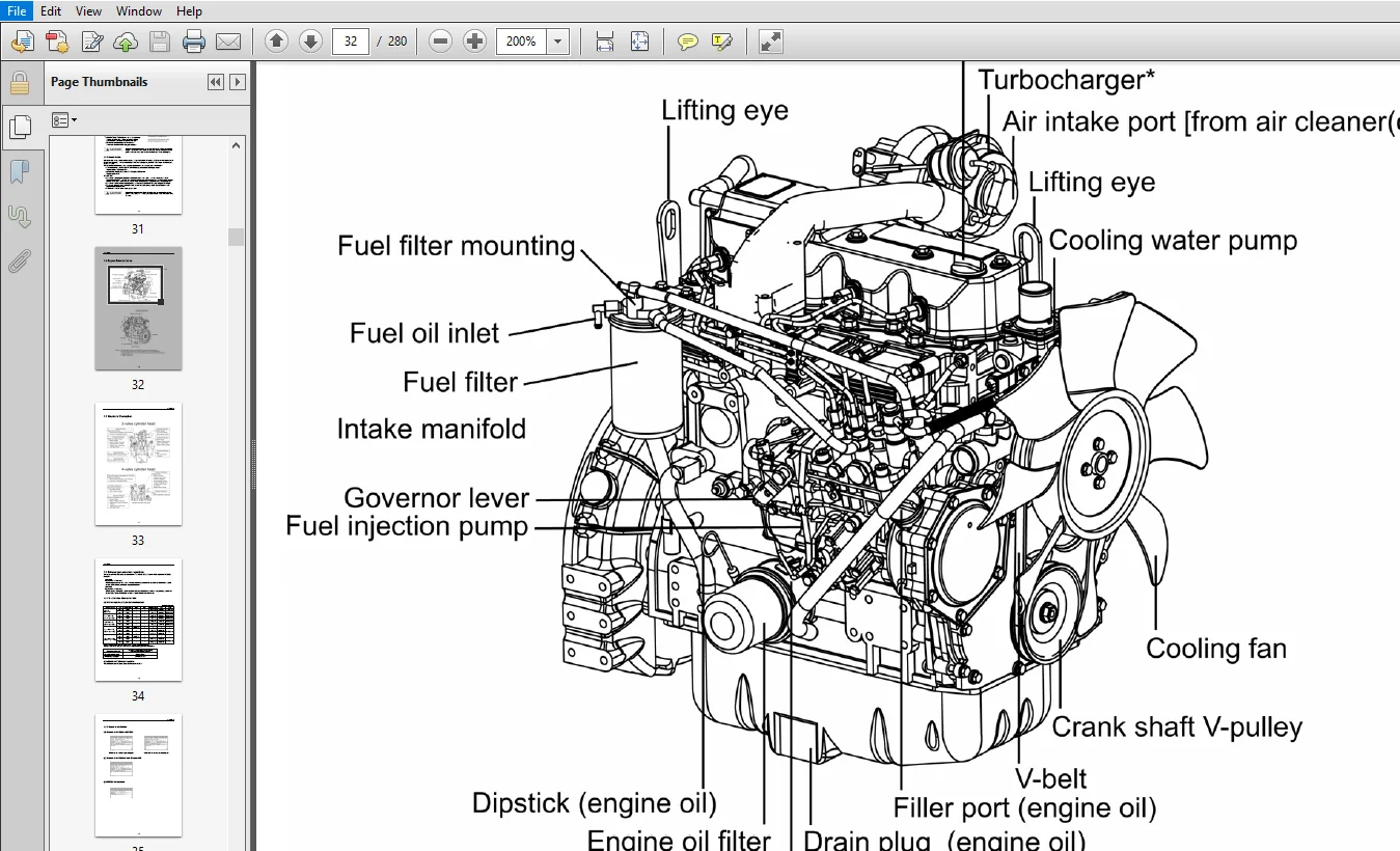
Engine_TNV.pdf..........................................................  0
	COVER...............................................................  0
	1. General.......................................................... 17
		1.1 Engine Nomenclature......................................... 17
		1.2 Specifications.............................................. 17
		1.3 Fuel Oil, Lubricating Oil and Coolant Water................. 30
			1.3.1 Fuel oil.............................................. 30
			1.3.2 Lubricating oil....................................... 31
			1.3.3 Coolant water......................................... 31
		1.4 Engine External Views....................................... 32
		1.5 Structural Description...................................... 33
		1.6 Exhaust gas emission regulation............................. 34
			1.6.1 The Emission Standard in USA.......................... 34
			1.6.2 Engine identification................................. 35
			1.6.3 Guarantee Conditions for the EPA Emission Standard.... 36
	2. Inspection and Adjustment........................................ 38
		2.1 Periodic Maintenance Schedule............................... 38
		2.2 Periodic Inspection and Maintenance Procedure............... 39
			2.2.1 Check before Daily Operation.......................... 39
			2.2.2 inspection after initial 50 hours operation........... 41
			2.2.3 Inspection every 50 hours............................. 44
			2.2.4 Inspection every 250 hours or 3 months................ 48
			2.2.5 Inspection every 500 hours or 6 months................ 51
			2.2.6 Inspection every 1,000 hours or one year.............. 53
			2.2.7 Inspection every 2000 hours or 2 years................ 62
		2.3 Adjusting the no-load maximum or minimum speed.............. 65
		2.4 Sensor Inspection........................................... 66
			2.4.1 Oil pressure switch................................... 66
			2.4.2 Thermo switch......................................... 66
		2.5 Water leak check in cooling water system.................... 66
		2.6 Radiator cap inspection..................................... 67
		2.7 Thermostat Inspection....................................... 67
		2.8 Adjusting Operation......................................... 68
		2.9 Long storage................................................ 68
	3. TROUBLESHOOTING.................................................. 69
		3.1 Preparation before troubleshooting.......................... 69
		3.2 Quick Reference Table for Troubleshooting................... 70
		3.3 Troubleshooting by measuring Compression Pressure........... 73
	4. Disassembly, Inspection and Reassembly of Engines................ 75
		4.1 Complete disassembly and reassembly......................... 75
			4.1.1 Introduction.......................................... 75
			4.1.2 Special service tools................................. 76
			4.1.3 Complete disassembly.................................. 81
			4.1.4 Precautions before and during reassembly.............. 85
			4.1.5 Adjusting operation................................... 85
		4.2 Cylinder Head: Disassembly, Inspection and Reassembly....... 86
			4.2.1 Components (2-valve cylinder head).................... 86
			4.2.2 Disassebly procedure:................................. 86
			4.2.3 Reassembly procedure:................................. 87
			4.2.4 Servicing points...................................... 88
			4.2.5 Parts Inspection and measurement...................... 92
			4.2.6 Valve seat correction................................. 96
			4.2.7 Valve guide replacement............................... 97
			4.2.8 Valve stem seal replacement........................... 98
		4.3 Gear Train and Camshaft..................................... 99
			4.3.1 Components............................................ 99
			4.3.2 Disassembly procedure:................................ 99
			4.3.3 Reassembly procedure:................................. 99
			4.3.4 Servicing points......................................100
			4.3.5 Parts inspection and measurement......................103
			4.3.6 Oil seal replacement (Gear case side).................105
			4.3.7 Camshaft bushing replacement..........................105
		4.4 Cylinder Block..............................................106
			4.4.1 Components............................................106
			4.4.2 Disassembly procedure:................................106
			4.4.3 Reassembly procedure:.................................106
			4.4.4 Servicing points......................................107
			4.4.5 Parts inspection and measurement......................111
			4.4.6 Cylinder bore correction..............................122
			4.4.7 Piston pin bushing replacement........................123
			4.4.8 Oil seal replacement (Flywheel housing side)..........123
	5. LUBRICATION SYSTEM...............................................124
		5.1 Lubrication System Diagram..................................124
		5.2 Trochoid Pump Components....................................125
		5.3 Disassembly(Reverse the procedure below for assembly).......125
		5.4 Servicing Points............................................125
		5.5 Parts Inspection and Measurement............................126
			5.5.1 Trochoid pump inspection and measurement..............126
	6. COOLING SYSTEM...................................................128
		6.1 Cooling Water System........................................128
		6.2 Cooling Water Pump Components...............................128
		6.3 Disassembly (Reverse the procedure below for assembly)......129
		6.4 Servicing Points............................................129
	7. FUEL INJECTION PUMP/GOVERNOR.....................................130
		7.1 Introduction................................................130
		7.2 Fuel Injection Pump.........................................130
			7.2.1 Fuel system diagram...................................130
			7.2.2 External view and components..........................131
			7.2.3 Disassembly procedure:................................131
			7.2.4 Assembly procedure....................................132
			7.2.5 Servicing points......................................132
	8. TURBOCHAGER: Disassembly, inspection and reassembly..............134
		8.1 Structure and Functions.....................................134
			8.1.1 Main specifications...................................134
			8.1.2 Construction..........................................134
			8.1.3 Structural and functional outline.....................135
			8.1.4 Components............................................136
		8.2 Service Standards and Tightening Torque.....................137
			8.2.1 Service standards.....................................137
			8.2.2 Tightening torque.....................................138
		8.3 Periodic Inspection Procedure...............................139
			8.3.1 Periodic inspection intervals.........................139
			8.3.2 Inspection procedure..................................140
			8.3.3 Waste gate valve adjustment procedure.................141
		8.4 Disassembly Procedure.......................................143
			8.4.1 Preparation for disassembly...........................143
			8.4.2 Inspection before disassembly.........................144
			8.4.3 Disassembly...........................................144
		8.5 Washing and Inspection procedure............................146
			8.5.1 Washing...............................................146
			8.5.2 Inspection procedure..................................147
		8.6 Reassembly Procedure........................................150
			8.6.1 Preparation for reassembly............................150
			8.6.2 Reassembly............................................150
		8.7 Handling after Disassembly and Reassembly...................153
			8.7.1 Instructions for turbocharger installation............153
		8.8 Troubleshooting.............................................154
			8.8.1 Excessively exhaust smoke.............................154
			8.8.2 White smoke generation................................154
			8.8.3 Sudden oil decrease...................................155
			8.8.4 Decrease in output....................................155
			8.8.5 Poor (slow) response (starting) of turbocharger.......155
			8.8.6 Abnormal sound or vibration...........................155
	9. STARTING MOTOR...................................................156
		9.1 For 4TNV94L/ 98.............................................156
			9.1.1 Specifications........................................156
			9.1.2 Components............................................157
			9.1.3 Troubleshooting.......................................158
			9.1.4 Names of parts and disassembly procedure..............159
			9.1.5 Inspection and Maintenance............................163
			9.1.6 Service standards.....................................168
			9.1.7 Assembly..............................................169
			9.1.8 Characteristic test...................................171
		9.2 For 4TNV106(T)..............................................172
			9.2.1 Specifications........................................172
			9.2.2 Congiguration drawing.................................172
			9.2.3 Troubleshooting.......................................173
			9.2.4 Component names and disassembly procedure.............174
			9.2.5 Disassembly procedure.................................175
			9.2.6 Inspection and maintenance............................183
			9.2.7 Assembly..............................................189
			9.2.8 Adjustment............................................190
			9.2.9 Service standards.....................................191
	10. ALTERNATOR......................................................192
		10.1 The 40A Alternator for 3TNV84 and other models.............192
			10.1.1 Components...........................................192
			10.1.2 Specifications.......................................193
			10.1.3 Wiring diagram.......................................193
			10.1.4 Standard output characteristics......................194
			10.1.5 Inspection...........................................194
			10.1.6 Troubleshooting......................................195
	11. ELECTRIC WIRING.................................................196
		11.1 Electric Wiring Diagram....................................196
		11.2 PRECAUTION ON ELECTRIC WIRING..............................197
			11.2.1 Alternator...........................................197
			11.2.2 Starter..............................................198
			11.2.3 Current limiter......................................199
			11.2.4 Section area and resistance of electric wire.........200
	12. SERVICE STANDARDS...............................................201
		12.1 Engine Tuning..............................................201
		12.2 Engine Body................................................202
			12.2.1 Cylinder head........................................202
			12.2.2 Gear train and camshaft..............................205
			12.2.3 Cylinder block.......................................206
		12.3 Lubricating Oil System (Trochoid Pump).....................211
	13. TIGHTENING TORQUE for BOLTS and NUTS............................212
		13.1 Tightening Torques for Main Bolts and Nuts.................212
		13.2 Tightening Torques for Standard Bolts and Nuts.............213
	BACK-ADDRESS........................................................  0
PLEASE NOTE:
- This is not a physical manual but a digital manual – meaning no physical copy will be couriered to you. The manual can be yours in the next 2 mins as once you make the payment, you will be directed to the download page IMMEDIATELY.
- This is the same manual used by the dealers inorder to diagnose your vehicle of its faults.
- Require some other service manual or have any queries: please WRITE to us at [email protected]


