Komatsu 4D98E-6SHA(4TNV98C),S4D98E-6VHA(4TNV98CT)Shop Manual PDF
$32.95
Komatsu Engine 4D98E-6SHA(4TNV98C),S4D98E-6VHA(4TNV98CT)Shop Manual VENBM09100 – PDF DOWNLOAD
Description
Komatsu Engine 4D98E-6SHA(4TNV98C),S4D98E-6VHA(4TNV98CT)Shop Manual VENBM09100 – PDF DOWNLOAD
FILE DETAILS:
Komatsu Engine 4D98E-6SHA(4TNV98C),S4D98E-6VHA(4TNV98CT)Shop Manual VENBM09100 – PDF DOWNLOAD
Language : English
Pages : 782
Downloadable : Yes
File Type : PDF
IMAGES PREVIEW OF THE MANUAL:
TABLE OF CONTENTS:
Komatsu Engine 4D98E-6SHA(4TNV98C),S4D98E-6VHA(4TNV98CT)Shop Manual VENBM09100 – PDF DOWNLOAD
Cover . 1
Table of Contents . 3
Introduction 5
Safety 7
Safety Statements . 9
Safety Precautions 10
During Operation and Maintenance 10
General Service Information . 23
Component Identification 25
3TNV88C, 3TNV86CT, 3TNV86CHT, 4TNV88C, 4TNV86CT, 4TNV86CHT 25
Location of Labels 27
Location of labels/nameplates on common rail system engine 27
Engine Nameplate (Typical) 28
Emission Control Regulations 28
EPA/ARB Regulations – USA Only 28
Emission Control Labels . 28
EPA/ARB labels (Typical) 28
EPA . 28
EPA and ARB . 28
The 97/68/EC Directive Certified Engines 29
Engine Family . 29
Function of Major Engine Components . 30
Function of Cooling System Components . 31
Main Electronic Control Components and Features . 32
Installation Position of Sensors 34
Cam Speed Sensor 35
New Air Temperature Sensor 36
EGR Temperature Sensor 36
Intake Temperature Sensor . 36
Cooling Water Temperature Sensor 37
Exhaust Temperature Sensor 38
Diesel Particulate Filter (DPF) Inside/Inlet Temperature Sensor . 38
Rail Pressure Sensor 38
EGR Pressure Sensor . 39
EGR Valve . 41
Intake Air Throttles 42
Exhaust Air Throttles . 43
Diesel Fuel . 45
Diesel Fuel Specifications 45
Additional technical fuel requirements 45
Precautions and concerns regarding the use of diesel fuel . 45
Biodiesel fuels . 45
Kit component for B20 (TNV Tier4 CR) 48
Filling The Fuel Tank . 49
Priming the Fuel System . 50
Engine Lubricating Oil 51
Engine Lubricating Oil Specifications . 51
Service categories 51
Definitions . 51
Additional technical engine lubricating oil requirements: . 51
Engine Lubricating Oil Viscosity 51
Checking Engine Lubricating Oil . 52
Adding Engine Lubricating Oil . 52
Engine Oil Capacity (Typical) . 52
Engine Coolant 53
Engine Coolant Specifications . 54
Alternative engine coolant 54
Filling Radiator with Engine Coolant 54
Daily Check of the Cooling System . 55
Engine Coolant Capacity (Typical) . 55
Specifications 56
Description of Model Number . 56
Engine General Specifications . 56
Principal Engine Specifications . 57
3TNV88C . 57
Engine Service Standards 66
Tightening Torques for Standard Bolts and Nuts 67
Abbreviations and Symbols . 68
Abbreviations . 68
Symbols . 68
Unit Conversions 69
Unit prefixes . 69
Units of length . 69
Units of volume . 69
Units of mass . 69
Units of force 69
Units of torque . 69
Units of pressure . 69
Units of power 69
Units of temperature 69
Periodic Maintenance 71
Before You Begin Servicing 73
Introduction 74
The Importance of Periodic Maintenance 74
Performing Periodic Maintenance . 74
YANMAR Replacement Parts 74
Required EPA/ARB Maintenance USA Only . 74
EPA/ARB Installation Requirements USA Only 74
Maximum exhaust gas restriction shall be: . 74
Periodic Maintenance Schedule . 75
Periodic Maintenance Procedures . 77
After Initial 50 Hours of Operation . 77
Check and adjust cooling fan V-belt . 77
Every 50 Hours of Operation . 78
Drain water separator . 78
Check battery . 80
Every 250 Hours of Operation 81
Drain fuel tank . 81
Check and clean radiator fins . 82
Check and adjust cooling fan V-belt . 82
Clean air cleaner element . 82
Every 500 Hours of Operation 83
Replace air cleaner element . 83
Replace fuel filter . 84
Replace water separator element . 85
Replace engine lubricating oil and oil filter . 86
Every 1000 Hours of Operation . 88
Check and adjust intake/exhaust valve clearance . 88
Every 1500 Hours of Operation . 88
Inspect crankcase breather system . 88
Every 2000 Hours of Operation . 89
Inspect and replace fuel line, coolant line, lubricating oil line, and breather hose 89
Lap the intake and exhaust valves . 89
Replace engine coolant 89
Every 3000 Hours of Operation . 91
Inspect ECU and related sensors and actuators . 91
Inspect turbocharger (blower wash as necessary) . 91
Inspect, clean and test EGR valve (except for engines with turbochargers) . 91
Cleaning the EGR cooler (water side/exhaust passage blower) . 91
Inspect DPF DOC . 92
Inspect and test intake throttle valve 92
Check the operation of exhaust throttle valve (optional) 92
Check and clean injector 92
At 6000 Hours of Operation 92
Check and clean of DPF soot filter 92
Engine 93
Before You Begin Servicing 95
INTRODUCTION 95
Cylinder Head Specifications 96
Adjustment Specifications . 96
Cylinder Head . 96
Rocker Arm and Shaft 98
Valve Spring 98
Camshaft and Timing Gear Train Specifications . 99
Camshaft 99
Timing Gear Backlash 100
Crankshaft and Piston Specifications 101
Crankshaft 101
Piston 102
Connecting rod small end 106
Connecting rod big end 106
Tappet 106
Cylinder Block Specifications .107
Cylinder Block 107
Special Torque Chart 108
Torque for Bolts and Nuts .108
Special Service Tools .111
Measuring Instruments .114
Cylinder Head .116
Cylinder Head Components 116
Disassembly of Cylinder Head 117
Removing the Glow Plugs .120
Removal of Cylinder Head Cover 120
Removal of Rocker Arm Assembly 120
Disassembly of Rocker Arm Assembly 121
Removal of Cylinder Head 121
Removal of Intake/exhaust Valves 122
Removal of Valve Guides .122
Cleaning of Cylinder Head Components 122
Inspection of Cylinder Head Components 123
Inspection of Push Rods .123
Push rod bend .123
Inspection of Rocker Arm Assembly .123
Rocker arm shaft hole diameter 123
Rocker arm shaft outside diameter .123
Inspection of Valve Guides 124
Inspection of Cylinder Head .124
Cylinder head distortion 124
Inspection of Intake and Exhaust Valves .124
Valve stem diameter .124
Valve stem bend .124
Valve recession .125
Valve face and valve seat .125
Inspection of Valve Springs .126
Fractures .126
Corrosion .126
Squareness 126
Free length .126
Reassembly of Cylinder Head .127
Reassembly of valve guides 127
Reassembly of intake and exhaust valves .127
Reassembly of cylinder head .128
Reassembly of rocker arm reassembly .129
Assembling the parts around the cylinder head .129
Measuring and Adjusting Valve Clearance .131
3-cylinder engines 131
4-cylinder engines 131
Crankshaft and Camshaft Components 133
Disassembly of Engine .134
Disassembly of Camshaft and Timing Components .135
Removal of timing gear case cover .135
Checking timing gear backlash .135
Measuring idler gear-to-crankshaft gear backlash 136
Measuring idler gear-to-camshaft gear backlash 136
Removal of timing gears .136
Removal of oil pan 137
Removal of camshaft .137
Removal of gear case 138
Disassembly of Crankshaft and Piston Components .139
Removal of pistons 139
Removal of crankshaft .140
Inspection of Crankshaft and Camshaft Components 142
Replacement of crankshaft oil seals .142
Measure crankshaft bearing oil clearance 143
Inspection of cylinder block 143
Inspection of pistons, piston rings and wrist pin .143
Inspection of connecting rod 145
Inspection of tappets .145
Inspection of crankshaft 146
Inspection of camshaft 146
Inspection of camshaft bushing and bores 147
Inspection of idler gear and shaft 147
Inspection of flywheel 147
Honing and Boring .148
Reassembly of Crankshaft and Piston Components 149
Reassembly of pistons .149
Installation of crankshaft 151
Installation of pistons .152
Reassembly of Camshaft and Timing Components 153
Installation of gear case .153
Installation of camshaft 154
Installation of timing gears 154
Installation of gear case cover .155
Installation of oil pan .156
Final Reassembly of Engine 156
EGR System 157
EGR System Configuration 157
Engine without turbocharger .157
Engine with turbocharger 158
EGR valve .159
EGR lead valve 159
EGR cooler 159
Disassembly of EGR System .159
EGR cooler 160
EGR valve/Lead valve 160
Cleaning the EGR Cooler (Water Side/Exhaust Passage Blower) .161
Cleaning the EGR Pipe and Other Connecting Elbows .161
Check, Clean, and Test EGR Valve 161
EGR active control 162
Cleaning the EGR valves .163
Exit the EGR active control .163
Precautions for cleaning 163
Cleaning the EGR Lead Valves 164
Precautions for installation 164
Assembling around the EGR Valve .164
Intake Throttle .165
Precautions for Handling the Intake Throttle 165
Exhaust Throttle 166
Checking the Operation of Exhaust Throttle 166
Fuel System .167
Before You Begin Servicing 169
System Structure 170
Supply pump .170
Rail 170
Injector 170
ECU .171
Fuel System Specifications 172
Torque Chart for Major Bolts and Nuts .172
Fuel System Diagram .173
Fuel System Components 174
Removal of Injector .175
Reassembly of injector 176
Removal of Common Rail 177
Reassembly of Common Rail .178
Removal of Supply Pump 179
Reassembly of Supply Pump .180
Cooling System 183
Before You Begin Servicing 185
INTRODUCTION 185
Cooling System Diagram 186
Engine Coolant Pump Components 187
Engine Coolant System Check .188
Engine Coolant Pump .188
Removal of Engine Coolant Pump 188
Disassembly of Engine Coolant Pump 189
Cleaning and Inspection .190
Temperature switch 190
Water temperature sensor 190
Thermostat 191
Radiator cap 191
Reassembly of Engine Coolant Pump .191
Installation of Engine Coolant Pump .192
Lubrication System 193
Before You Begin Servicing 195
Introduction 195
Oil Pump Service Information 196
Engine lubricating oil pressure .196
Outer rotor outside clearance .196
Outer rotor side clearance 196
Outer rotor to inner rotor tip clearance 196
Rotor shaft clearance .197
Lubrication System Diagram 198
Checking Engine Lubricating Oil Pressure 199
Oil Pump Components .199
3TNV88C, 3TNV86CT, 3TNV86CHT, 4TNV88C, 4TNV86CT, 4TNV86CHT 199
Disassembly of Oil Pump .199
Cleaning and Inspection .200
Check outer rotor outside clearance .200
Outer rotor to inner rotor tip clearance 200
Check outer rotor side clearance 201
Check rotor shaft clearance .201
Reassembly of Oil Pump 201
4TNV98C, 4TNV98CT (Trochoid Oil Pump) .202
Disassembly of Oil Pump .202
Cleaning and Inspection .203
Check outer rotor outside clearance .203
Outer rotor to inner rotor tip clearance 203
Check outer rotor side clearance 203
Check rotor shaft clearance .204
Reassembly of Oil Pump 204
Turbocharger 205
Before You Begin Servicing 207
Introduction 207
Specifications 207
Turbocharger Service Information 207
Troubleshooting .208
Excessive exhaust smoke .208
Sudden oil decrease .209
Decrease in output 209
Poor (slow) response (starting) of turbocharger .209
Abnormal sound or vibration .209
Turbocharger Components .210
Turbocharger Component Functions 211
Structure of Turbocharger .211
Turbine .211
Compressor 211
Bearings 212
Compressor side sealing mechanism .212
Role of Waste Gate 212
Periodic Inspection .213
Visual Inspection .213
Inspection of Rotor Rotation 213
Checking Rotor Play .213
To check rotor end play: 213
To check rotor run-out: .213
Waste Gate Valve Test .214
Waste Gate Actuator Leak Test .214
Removal and Installation of turbocharger 215
Removal of Turbocharger .215
Installation of Turbocharger 215
Cleaning Procedure 216
Starter Motor .217
Before You Begin Servicing 219
INTRODUCTION 219
Starter Motor Information .220
3TNV88C to 4TNV86CHT – Standard and Optional 220
4TNV98C and 4TNV98CT – Standard and Optional 220
Starter Motor Specifications 221
Starter Motor Troubleshooting .222
Starter Motor Components 223
Starter Motor .224
Removal of Starter Motor 224
Disassembly of Starter Motor 224
Cleaning and Inspection .226
Armature 226
Field coil 227
Magnetic switch .228
Pinion clutch assembly 229
Reassembly of Starter Motor .229
Check Pinion Projection Length 231
No-Load Test 231
Installation of Starter Motor .232
Alternator 233
Before You Begin Servicing 235
Introduction 236
Dynamo and Alternator Information .236
3TNV88C to 4TNV98CT – Standard and Optional Dynamos .236
3TNV88C to 4TNV98CT – Standard and Optional Alternators .236
Alternator Specifications .237
Dynamo Specifications .237
Alternator Troubleshooting 238
Alternator Components .239
Alternator Wiring Diagram .240
Alternator Standard Output 241
Alternator 242
Removal of Alternator .242
Disassembly of Alternator .243
Reassembly of Alternator 244
Installation of Alternator 246
Dynamo Component Location .248
Dynamo Wiring Diagram .249
Operation of Dynamo .249
Dynamo Standard Output 250
Testing of Dynamo .251
Testing Stator Coil Continuity 251
Testing Stator Coil Short-to-Ground .251
Testing Dynamo Regulated Output .251
Dynamo 251
Removal of Dynamo .251
Disassembly of Dynamo .252
Reassembly of Dynamo 252
Installation of Dynamo 253
Electronic Control System .255
Before You Begin Servicing 257
Introduction 257
System Structure 258
Diesel Particulate Filter (DPF) .259
Overview of Diesel Particulate Filter (DPF) regeneration control 260
Self-regeneration .260
Assisted regeneration .260
Reset regeneration 260
Stationary regeneration .261
Operation procedures of stationary regeneration .261
Precautions for stationary regeneration .261
Recovery regeneration (optional) 262
Precautions for recovery regeneration .262
Diesel Particulate Filter (DPF) service .263
Procedures for servicing the Diesel Particulate Filter (DPF) 263
HOW TO REMOVE AND REATTACH THE DIESEL PARTICULATE FILTER (DPF) 264
How to remove the soot filter (SF) case .264
How to reattach the SF case .267
How to remove the DPF unit 269
How to reattach the DPF .271
SF and DPF Maintenance Kit 274
Troubleshooting of Electronic Control System 276
Fault Detection Capability 276
SMARTASSIST-DIRECT (SA-D) .277
About SA-D use 278
Replacement of Components .279
Processing the DPF regeneration after the parts replacement .279
Processing after the ECU replacement (when it is impossible to inherit from the old ECU) 280
Required processing at the CR-related parts replacement .281
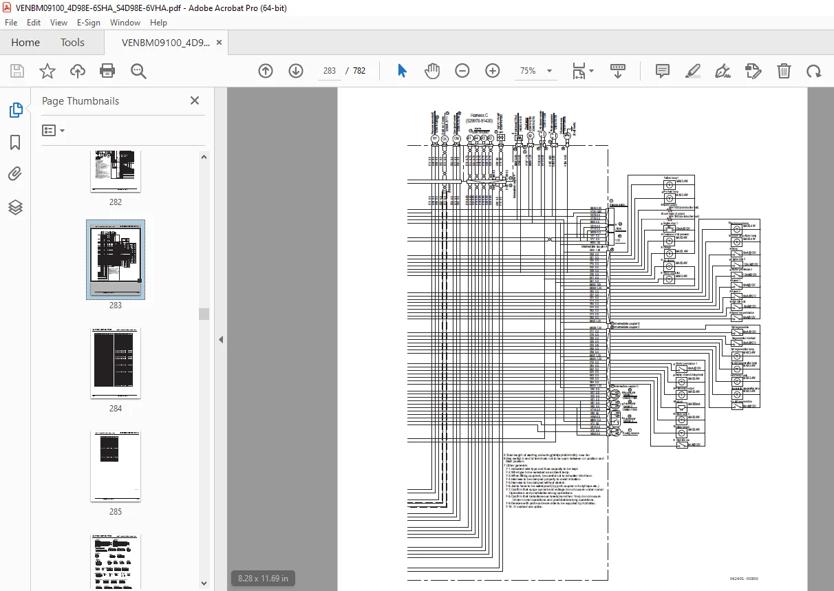
Electronic Control Harness Connections 282
Electric Wiring .289
Electric Wiring Precautions .291
Electrical Wire Resistance 292
Battery Cable Resistance 293
Electrical Wire Sizes – Voltage Drop 294
Conversion of AWG to European Standards .295
Failure Diagnosis .297
Special Service Tools .299
Troubleshooting by Measuring Compression Pressure .300
Compression Pressure Inspection Procedures 300
Attaching the Injector 301
Engine Speed And Compression Pressure (Use For Reference) .302
Measured Value and Troubleshooting 303
Quick Reference Table for Troubleshooting .304
Failure Diagnostic List .305
Troubledhooting .309
CONTENTS 311
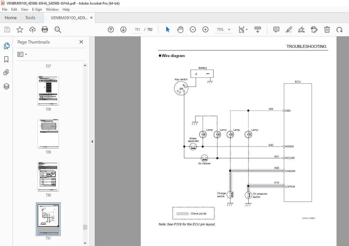
TROUBLESHOOTING .319
DTC (Diagnostic Trouble Codes) General Description 319
Method and Procedure of Failure Diagnosis .633
DESCRIPTION:
Komatsu Engine 4D98E-6SHA(4TNV98C),S4D98E-6VHA(4TNV98CT)Shop Manual VENBM09100 – PDF DOWNLOAD
- INTRODUCTION:
- This Service Manual describes the service procedures for the TNV series engines have common rail injection system. These engines are certified by the U.S. EPA, California ARB and/or the 97/68/EC Directive for industrial use.
- Please use this manual for accurate, quick and safe servicing of the engine. Since the directions in this manual are for a typical engine, some specifications and components may be different from your engine. Refer to the documentation supplied by the optional equipment manufacturer for specific service instructions.
- For the replacement of some parts and troubleshooting for the TNV series engines, the Komatsu Diagnostics Tool called SMART ASSIST Direct is required. In addition, please read both Troubleshooting Manual and SMART ASSIST Direct Operation Manual.
- Komatsu products are continuously undergoing improvement. This Service Manual might not address possible field modifications to the equipment. Contact an authorized Komatsu industrial engine dealer or distributor for answers to any questions relating to field modifications.
G.B 28/12/24


