Komatsu 66C 66D turbo HYDRAULIC SYSTEM Workshop Handbook Manual 3072 517 M1 – PDF DOWNLOAD
Original price was: $89.00.$29.95Current price is: $29.95.
Komatsu 66C, 66D turbo HYDRAULIC SYSTEM Workshop Handbook Manual 3072 517 M1 – PDF DOWNLOAD
Description
Komatsu 66C 66D turbo HYDRAULIC SYSTEM Workshop Handbook Manual 3072 517 M1 – PDF DOWNLOAD
IMAGES PREVIEW OF THE MANUAL:
DESCRIPTION:
Komatsu 66C 66D turbo HYDRAULIC SYSTEM Workshop Handbook Manual 3072 517 M1 – PDF DOWNLOAD
PREFACE and EXPLANATIONS
- This manual should assist the skilled construction machine mechanic when carrying out repairs and adjustments оп MF construction machines. The procedures аге written in such а style that the dismantling and assemЬling of the components can Ье carried out successfully and without difficulty.
- То assist in the locating of specific test-repair operations, working description etc. this manual is divided into main and sub-groups. This also applies to all types of service manuals.
- At the top right hand corner of every page next to the section heading а series of numbers (orientation number) аге to Ье found. These numbers follow in numerical sequence throughout the book.
- The section heading applies either to the construction machine type, assemЬly ог component for which the text and illustrations аге valid
LOADER .and STEERING HYDRAULICS
loader hydraulics
А two–stage system where the outputs of the loader pump and switch pump are controlled dependent оп system load.
The system 1s remote controlled via а servo control system.
Steering hydraulics
Articulated steering system with ZF hydro-steering column assemЫy and two steerlng
cylinders. Constant oil supply Ьу the steering and switch pumps over the complete engine speed
range. With the engine stopped, oil supply to steerlng system maintained Ьу the ZF emergency
steering pump
TABLE OF CONTENTS:
Komatsu 66C 66D turbo HYDRAULIC SYSTEM Workshop Handbook Manual 3072 517 M1 – PDF DOWNLOAD
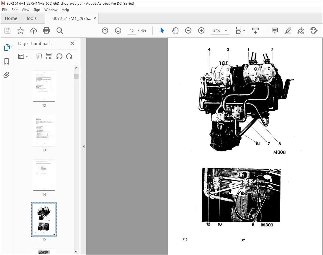
Working {loader) hydraulics
11 lustrations of the individual components
Hydraulic diagram of working hydraulics with servo control
and steering circuits
Hydraulic diagram with 3-spool control valve and related
electrical system
Functional description
Control spool valve
Description and arrangement of the connections
Cross sectional view
Cross sectional view of the 3-spool control valve
Descr!ption of the secondary pressure relief valve {shock valve)
Demand/regu lating va I ve
Description and arrangement of the connections
Functional description
Pressure rel ief valve (servo controL)
Description and arrangement of the connections
Servo control valve
Description and arrangement of the connections
Description and arrangement of the connections (3-spool)
Cross sectional view of the 3-spool servo control valve
Pipe connection Ыосk for servo control valve
Pipe connection Ыосk for servo control valve (3-spool)
Directional valve
Description and arrangement of the connections
SUB GROUP 2
Working (loader) hydraulics
Fault diagnosis and possiЫe remedies
Control spool valve
Secondary pressure relief valve (shock valve) testing
Т est method 1
Т est method 2
2~stage pressure relief valve, pressure testing and adjustin-g
Spool valve stroke limiters,• adjusting
Pressure valve group in the float valve (emergency lowering},
adjusting
Demand/regulating valve
Regulating pressure, testing and adjusting
Pressure relief valve
Pressure testing and adjusting
Servo control valve
Switch for tip-in and dump-out, adjusting
Lift (loader} and bucket cylinders
Leakage tests
Тest method 1
Тest method 2
Тest method З
Flow capacities measuring
Oil tank
Removing and refitting
External fittings, removing and refitting
Hydraulic pump (loader pump)
Removing and refitting
External fittings, removing and refitting
Reconditioning
Hydrau I ic pump (switch pump)
Removing and refitting
External fittings, removing and refitting
Reconditioning
·control spool valve
· Removing and refitting
External fittings, removing and refitting
Secondary pressure relief valve (shock valve) reconditioning
Anti-cavitation valve, reconditioning
2-stage pressure relief valve, reconditioning
Spool valve stroke limiters, reconditioning
Spool valves, reconditioning
Float valve, reconditioning
Spool group, recond ition ing
Pressure valve group, reconditioning
Return flow manifold
Removing and refitting
External fittings, removing and refitting
Reconditioning
Demand/regulating valve
Removing and refitting
External fittings, removing and refitting
Reconditioning
Regulating valve, complete, removing from the demand valve
Regulating valve, reconditioning
Check valve in regulating valve, reconditioning
Control spool in regulating valve, reconditioning
Demand valve, reconditioning
Hydraulic pump (servo control)
Removing and refitting
External fittings, removing and refitting
Reconditioning
Pressure relief valve {servo control)
Removing and refitting
External fittings, removing and refitting
Reconditioning
Servo control valve
Removing and refitting
Reconditioning
Spring in control valve lever, removing and refitting
Control valve lever complete and upper seals, removing and
refitting
Switch for “Тip-in II and ”Dump-out”, removing and refitting
Spool reset group for “Тip-in” and “Dump-out 11
reconditioning
Spool reset group for ”Lift” and 11 Lower 11
reconditioning
Directional valve
Removing and refitting
Mounting plate, removing and refitting
Lift {loader) cyl inders
Removing and refitting
ExternaJ fittings, removing and refitting
Lift (\oader) cylinder (version 1), reconditioning
Piston rod packing seal, fitting
Piston seals and guide Ьands, refitting
Wrapped bushes, removing and refitting
Lift {loader) cylinder (version 2) ,_ reconditioning
Piston seals and guide Ьands, refitting
Wrapped bushes, removing and refitting
Bucket cylinders
Removing and refitting
External fittings, removing and refitting
Version 1, reconditioning
Version 2, reconditioning
Lift and bucket cylinders
Application of 11 Loctite” to piston rod threads
SUB GROUP 5
Technical data
Torque tightening limits
Lift and- bucket cyl inders
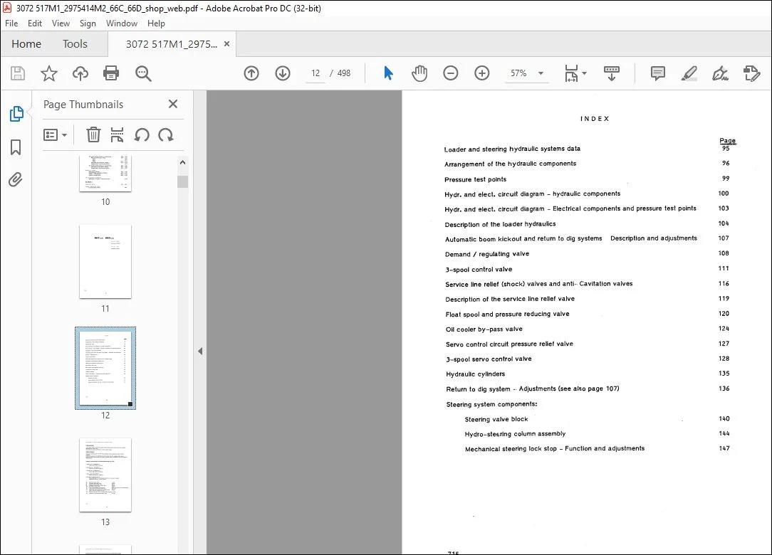
Loader and steering hydraulic systems data
Arrangement of the hydraulic components
Pressure test polnts
1 N D Е Х
Hydr. and elect. circult dlagram – hydrau/ic components
Hydr. and elect. circuit diagram – Electrical components and pressure test points
Description of the loader hydraulics
Automatlc boom kickout and return to dig systems Description and adjustments 107
Demand / regulating valve
3-spool control valve
Service line relief (shock) valves and anti-• Cavitation valves
Description of the service line rellef valve
Float spool and pressure reducing valve
Oil cooler by-pass valve
Servo control circuit pressure relief valve
3-spool servo control valve
H)·draulic cylinders
Return to dig system -· Adjustments (see also page 107)
Steering system components:
Steering valve Ыосk
Hydro-steE::ring column assemЫy
Mechanical steering lock stop – Function and adjustments
Customer Support: [email protected]
https://vimeo.com/743319016
PLEASE NOTE:
- This is the SAME exact manual used by your dealers to fix your vehicle.
- The same can be yours in the next 2-3 mins as you will be directed to the download page immediately after paying for the manual.
- Any queries / doubts regarding your purchase, please feel free to contact [email protected]
S.m


