Komatsu 685E Dump Truck Shop Manual DG607 PDF
$32.95
Komatsu 685E Dump Truck Shop Manual DG607 – PDF DOWNLOAD
AFE43-A thru AFE43-AD
Description
Komatsu 685E Dump Truck Shop Manual DG607 – PDF DOWNLOAD
FILE DETAILS:
Komatsu 685E Dump Truck Shop Manual DG607 – PDF DOWNLOAD
Language : English
Pages : 783
Downloadable : Yes
File Type : PDF
DESCRIPTION:
Komatsu 685E Dump Truck Shop Manual DG607 – PDF DOWNLOAD
AFE43-A thru AFE43-AD
- This Service Manual is written for use Ьу the service technician and is designed to help the technician
become fully knowledgeaЫe of the truck and all its systems in order to keep it running and in
production. AII maintenance personnel should read and understand the materials in this manual
before performing maintenance and/or operational checks оп the truck. AII safety notices, wamings
and cautions should Ье understood and followed when accomplishing repairs оп the truck. - The first section covers component descriptions, truck speciflcations and safe work practices, as well
as other general lnformation. The major portion of the manual pertains to disassemЫy, service and
reassemЫy. Each major serviceaЫe area is dealt with individually. For example: The disassemЫy,
service and reassemЫy of the radiator group is dlscussed as а unlt. The same is true of the engine
and engine accessories, and so on through the entire mechanical detall of the truck. DisassemЫy
should Ье carried only as far as necessary to accomplish needed repairs. - The lllustrations used in this manual are, at tlmes, typical of the component shown and may not
necessarily depict а specific model. - This manual shows dimensioning of U.S. standard and metric (SI) units throughout and all references
to “Righr’, “Left”, “Front”, or “Rear” are made with respect to the operator’s normal seated position,
unless specifically stated otherwise. - Standard torque requirements are shown in torque charts in the general information section and
individual torques are provided in the text in bold face type, such as 100 ft.lbs. {135 N.m) torque. А/1
torque specifications have ± 10% tolerance unless otherwise specified. - А Product ldentiflcation plate is normally located on the truck frame in front of the right side front
wheel and designates the Truck Model Number, Product ldentification NumЬer (vehicle serial
number), and Maximum G.V.W. (Gross Vehlcle Weight) ratlng. - The HAULPAK® Model designation consists of three numЬers and one letter (i.e. 685Е). The three
numbers represent the Ьasic truck model. The letter “М” designates а Mechanical drive and the letter
“Е” designates an Electrical propulsion system. - The Product ldentification Number (vehlcle serial numЬer) contains informatlon which wUI ldentify the
original manufacturing ЫII of material for thls unit. This complete number w\11 Ье necessary for proper
ordering of many service parts and/or warranty conslderation. - The Gross Vehicle Weight (GVW) is what determines the load on the drive train, frame, tires, ancl other
components. The vehicle design and appllcation guidelinesare sensltive to thetotal maximum Gross
Vehcle Weight (GVW) and this means the total weight: the Empty Vehicle Welght + the fuel &
lubricants + the payload.
TABLE OF CONTENTS:
Komatsu 685E Dump Truck Shop Manual DG607 – PDF DOWNLOAD
AFE43-A thru AFE43-AD
Cover 1
00 Index and foreword 3
Index 3
Composition of shop manual 4
Table of contents 6
Foreword and general information 17
Safety notice 18
How to read the shop manual 23
Explanation of terms for maintenance standard 25
Handling of electric equipment and hydraulic component 27
Handling of connectors newly used for engines 36
How to read electric wire code 39
Precautions when carrying out operation 42
Method of disassembling and connecting push-pull type coupler 45
Standard tightening torque table 48
Conversion table 52
01 Specification 59
Specification and technical data 59
Specification and technical data 60
Specification drawings 60
Working range drawing 62
Specifications 64
Weight table 82
Table of fuel, coolant and lubricants 88
10 Structure, function and maintenance standard 91
Engine and cooling system 91
Engine and cooling system 92
Coupling 92
Coupling lubrication system 93
Radiator, oil cooler 94
Power train 97
Power train 98
Power train 98
Swing machinery 100
Swing circle 102
Final drive 104
Sprocket 106
Undercarriage and frame 109
Undercarriage and frame 110
Track frame and recoil spring 110
Idler 112
Carrier roller 114
Track roller 116
Track shoe 118
Hydraulic system, Part 1 123
Hydraulic system, Part 1 124
Hydraulic piping drawing 124
Hydraulic tank, hydraulic filter 126
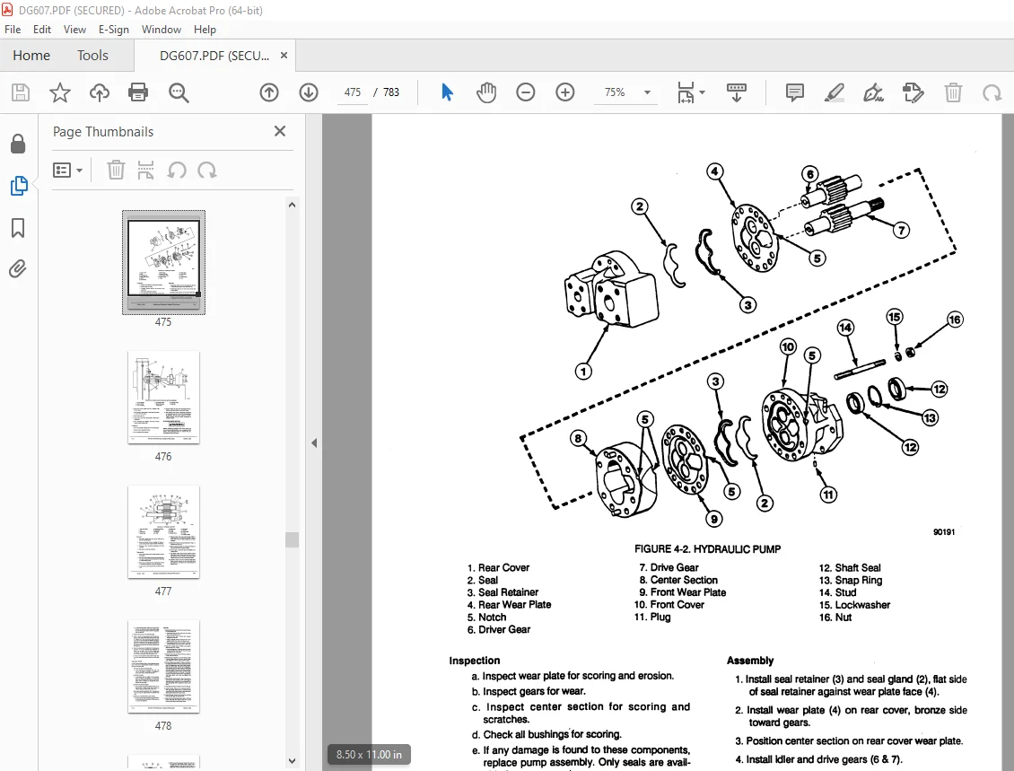
Hydraulic pump 128
Cooling fan pump 148
Cooling fan motor 156
Hydraulic system, Part 2 163
Hydraulic system, Part 2 166
Motor grease pump 166
Return oil filter 167
Line oil filter 168
Drain oil filter 169
L H 5-Spool control valve 170
R H 4-Spool control valve 176
Straight-travel valve 182
Swing motor 185
Center swivel joint 190
Travel motor 191
PPC accumulator 201
Work equipment, swing PPC valve 202
Travel PPC valve 207
Anti-drop valve 211
Solenoid valve 212
Quick return valve 218
Hydraulic cylinder 220
Work equipment 227
Work equipment 228
Work equipment 228
Dimensions of work equipment 234
Cab and its attachments 239
Cab and its attachments 240
Air conditioner piping 240
Electrical system 243
Engine control 244
Electric control system 253
Monitor system 287
Sensors 305
KOMTRAX system 309
20 Standard value table 313
Standard service value table 313
Standard service value table 314
Standard service value table for engine 314
Standard service value table for chassis 315
30 Testing and adjusting 327
Testing and adjusting, Part 1 327
Testing and adjusting, Part 1 328
Tools for testing, adjusting and troubleshooting 328
Measuring engine speed 331
Measuring intake air pressure (Boost pressure) 332
Measuring exhaust gas temperature 333
Measuring exhaust gas color 334
Adjusting valve clearance 335
Measuring compression pressure 336
Measuring blow-by pressure 337
Measuring engine oil pressure 338
Measuring EGR valve and bypass valve drive pressure 339
Handling of fuel system equipment 340
Remaining pressure relief from fuel system equipment 340
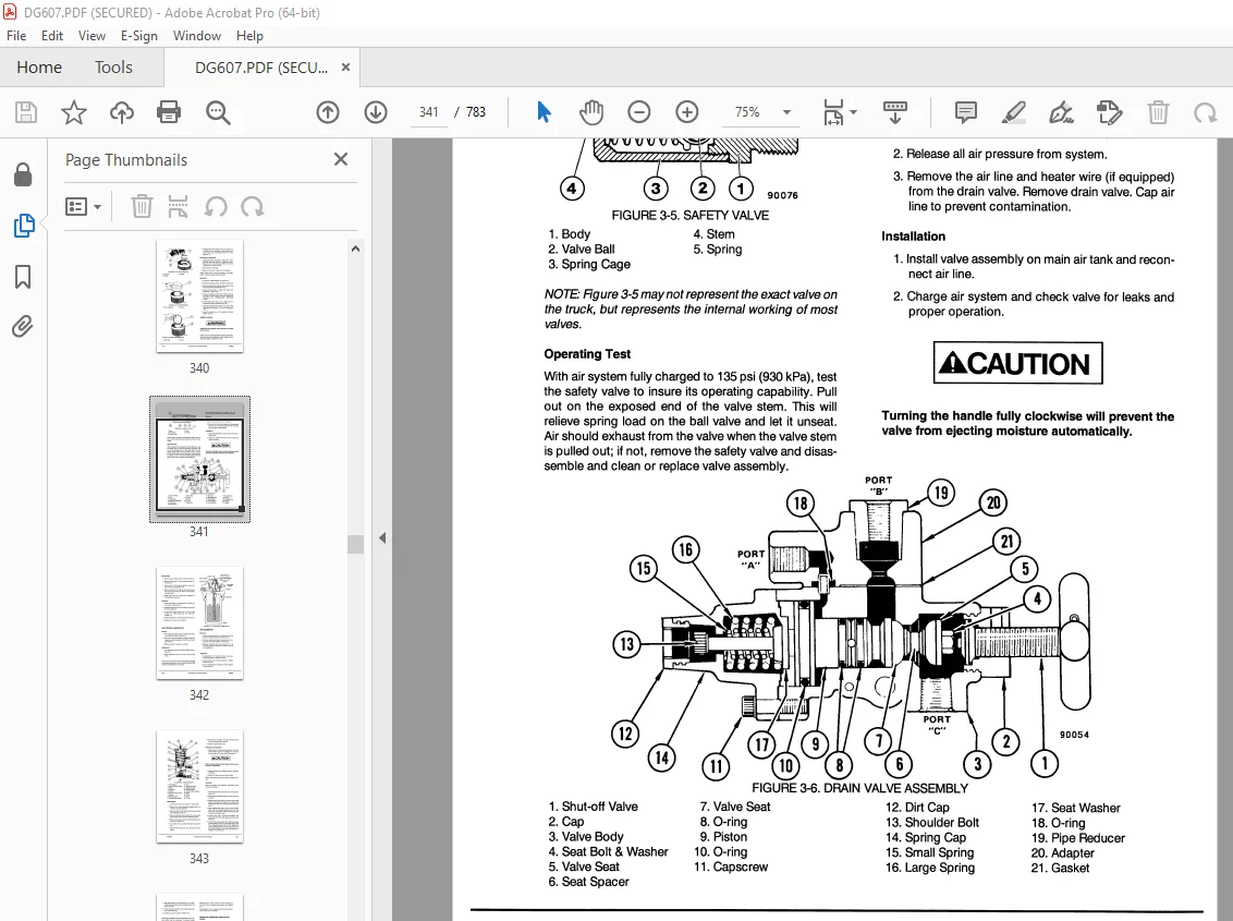
Measuring fuel pressure 341
Testing fuel return rate and leakage 342
Bleeding air from fuel circuit 344
Testing fuel system for leakage 346
Testing and adjusting alternator belt tension 347
Testing and adjusting air conditioner compressor belt 348
Testing and adjusting, Part 2 351
Testing and adjusting, Part 2 352
Inspection of swing circle bearing clearance 352
Testing and adjusting track shoe tension 353
Testing and adjusting work equipment, swing, and travel circuit oil pressures 354
Testing and adjusting control circuit pressure (output pressure of self pressure reducing valve) 360
Testing and adjusting main pump control pressure 362
Testing and adjusting, Part 3 369
Testing and adjusting, Part 3 370
Measuring PPC valve output pressure 370
Measuring outlet pressures of solenoid valve, swing PPC shuttle valve, and swing priority selector valve 374
Adjusting work equipment, swing PPC valve 378
Testing and adjusting travel deviation 379
Inspection of locations of hydraulic drift of work equipment 381
Measuring fan speed 382
Measuring fan circuit oil pressure 382
Measuring fan pump EPC current 383
Measuring fan pump EPC solenoid valve output pressure 384
Measuring oil leakage 385
Release of residual pressure from hydraulic circuit 389
Bleeding air from each part 390
Inspection procedures for diode 393
Adjusting mirrors 394
Testing and adjusting, Part 4 397
Testing and adjusting, Part 4 398
Special function of machine monitor 398
Handling controller voltage circuit 431
Testing and adjusting, Part 5 433
Testing and adjusting, Part 5 434
Procedure for turning on KOMTRAX terminal 434
KOMTRAX terminal lamp indications 437
Preparation work for troubleshooting electrical system 440
Pm-clinic service 443
40 Troubleshooting 453
Failure code table and fuse locations 453
Failure code table and fuse locations 454
Failure codes table 454
Fuse locations 458
General information on troubleshooting 461
General information on troubleshooting 462
Points to remember when troubleshooting 462
Sequence of events in troubleshooting 463
Checks before troubleshooting 464
Classification and troubleshooting steps 465
Information in troubleshooting table 466
Failure-looking phenomenon and troubleshooting No 468
Connection table for connector pin numbers 471
T- branch box and T- branch adapter table 507
Troubleshooting by failure code (Display of code), Part 1 511
Troubleshooting by failure code (Display of code), Part 1 514
Failure code [AA10NX] Aircleaner Clogging 514
Failure code [AB00KE] Charge Voltage Low 516
Failure code [B@BAZG] Eng Oil Press Low 518
Failure code [B@BAZK] Eng Oil Level Low 519
Failure code [B@BCNS] Eng Water Overheat 520
Failure code [B@BCZK] Eng Water Lvl Low 522
Failure code [B@HANS] Hydr Oil Overheat 524
Failure code [CA111] ECM Critical Internal Failure 526
Failure code [CA115] Eng Ne and Bkup Speed Sens Error 528
Failure code [CA122] Chg Air Press Sensor High Error 530
Failure code [CA123] Chg Air Press Sensor Low Error 532
Failure code [CA131] Throttle Sensor High Error 534
Failure code [CA132] Throttle Sensor Low Error 536
Failure code [CA135] Eng Oil Press Sensor High Error 538
Failure code [CA141] Eng Oil Press Sensor Low Error 540
Failure code [CA144] Coolant Temp Sens High Error 542
Failure code [CA145] Coolant Temp Sens Low Error 544
Failure code [CA153] Chg Air Temp Sensor High Error 546
Failure code [CA154] Chg Air Temp Sensor Low Error 548
Failure code [CA187] Sens Supply 2 Volt Low Error 548
Failure code [CA221] Ambient Press Sens High Error 550
Failure code [CA222] Ambient Press Sens Low Error 552
Failure code [CA227] Sens Supply 2 Volt High Error 554
Failure code [CA234] Eng Overspeed 556
Failure code [CA238] Ne Speed Sens Supply Volt Error 558
Failure code [CA263] Fuel Temp Sensor High Error 560
Failure code [CA265] Fuel Temp Sensor Low Error 562
Failure code [CA271] IMV/PCV1 Short Error 563
Failure code [CA272] IMV/PCV1 Open Error 564
Failure code [CA273] PCV2 Short Error 565
Failure code [CA274] PCV2 Open Error 566
Failure code [CA322] Inj #1 (L#1) Open/Short Error 567
Failure code [CA323] Inj #5 (L#5) Open/Short Error 568
Failure code [CA324] Inj #3 (L#3) Open/Short Error 570
Failure code [CA325] Inj #6 (L#6) Open/Short Error 572
Failure code [CA331] Inj #2 (L#2) Open/Short Error 574
Failure code [CA332] Inj #4 (L#4) Open/Short Error 576
Failure code [CA342] Calibration Code Incompatibility 577
Failure code [CA351] Injectors Drive Circuit Error 578
Failure code [CA352] Sens Supply 1 Volt Low Error 580
Failure code [CA386] Sens Supply 1 Volt High Error 582
Troubleshooting by failure code (Display of code), Part 2 585
Troubleshooting by failure code (Display of code), Part 2 587
Failure code [CA441] Battery Voltage Low Error 587
Failure code [CA442] Battery Voltage High Error 587
Failure code [CA449] Rail Press Very High Error 588
Failure code [CA451] Rail Press Sensor High Error 590
Failure code [CA452] Rail Press Sensor Low Error 592
Failure code [CA553] Rail Press High Error 592
Failure code [CA554] Rail Press Sensor In Range Error 593
Failure code [CA559] Rail Press Low Error 594
Failure code [CA689] Eng Ne Speed Sensor Error 598
Failure code [CA731] Eng Bkup Speed Sens Phase Error 600
Failure code [CA757] All Persistent Data Lost Error 601
Failure code [CA778] Eng Bkup Speed Sensor Error 602
Failure code [CA1228] EGR Valve Servo Error 1 604
Failure code [CA1625] EGR Valve Servo Error 2 605
Failure code [CA1626] BP Valve Sol Current High Error 606
Failure code [CA1627] BP Valve Sol Current Low Error 608
Failure code [CA1628] Bypass Valve Servo Error 1 609
Failure code [CA1629] Bypass Valve Servo Error 2 610
Failure code [CA1631] BP Valve Pos Sens High Error 612
Failure code [CA1632] BP Valve Pos Sens Low Error 614
Failure code [CA1633] KOMNET Datalink Timeout Error 616
Failure code [CA1642] EGR Inter Press Sens Low Error 618
Failure code [CA1653] EGR Inter Press Sens High Error 620
Failure code [CA2185] Throt Sens Sup Volt High Error 622
Failure code [CA2186] Throt Sens Sup Volt Low Error 624
Failure code [CA2249] Rail Press Very Low Error 625
Failure code [CA2271] EGR Valve Pos Sens High Error 626
Failure code [CA2272] EGR Valve Pos Sens Low Error 628
Failure code [CA2351] EGR Valve Sol Current High Error 630
Failure code [CA2352] EGR Valve Sol Current Low Error 632
Failure code [CA2555] Grid Htr Relay Volt Low Error 633
Failure code [CA2556] Grid Htr Relay Volt High Error 634
Failure code [D110KB] Battery Relay Drive S/C 636
Failure code [D163KB] Flash Light Relay S/C 638
Failure code [D195KB] Step Light Relay S/C 640
Failure code [DA22KK] Pump Solenoid Power Low Error 642
Failure code [DA25KP] Press Sensor Power Abnormality 644
Failure code [DA2SKQ] Model Selection Abnormality 646
Failure code [DA80MA] Auto Lub Abnormal 648
Failure code [DA2RMC] Pump Comm Abnormality 650
Failure code [DAFRMC] Monitor Comm Abnormality 652
Failure code [DGE5KY] Ambi Temp Sensor S/C 654
Failure code [DGH2KB] Hydr Oil Temp Sensor S/C 656
Troubleshooting by failure code (Display of code), Part 3 659
Troubleshooting by failure code (Display of code), Part 3 662
Failure code [DH25KA] L Jet Sensor Disc 662
Failure code [DH25KB] L Jet Sensor S/C 664
Failure code [DH26KA] R Jet Sensor Disc 666
Failure code [DH26KB] R Jet Sensor S/C 668
Failure code [DHPEKA] F Pump P Sensor Disc 670
Failure code [DHPEKB] F Pump P Sensor S/C 672
Failure code [DHPFKA] R Pump P Sensor Disc 674
Failure code [DHPFKB] R Pump P Sensor S/C 676
Failure code [DV20KB] Travel Alarm S/C 678
Failure code [DW41KA] Swing Priority Sol Disc 680
Failure code [DW41KB] Swing Priority Sol S/C 682
Failure code [DW43KA] Travel Speed Sol Disc 684
Failure code [DW43KB] Travel Speed Sol S/C 686
Failure code [DW45KA] Swing Brake Sol Disc 688
Failure code [DW45KB] Swing Brake Sol S/C 690
Failure code [DW7BKA] Fan Reverse Sol Disc 692
Failure code [DW7BKB] Fan Reverse Sol S/C 694
Failure code [DW7JKA] Bottom Dump Priority Sol Disc 696
Failure code [DW7JKB] Bottom Dump Priority Sol S/C 698
Failure code [DWK0KA] 2-stage Relief Sol Disc 700
Failure code [DWK0KB] 2-stage Relief Sol S/C 702
Failure code [DX16KA] Fan Pump EPC Sol Disc 704
Failure code [DX16KB] Fan Pump EPC Sol S/C 706
Failure code [DXAAKA] F Pump EPC Sol Disc 708
Failure code [DXAAKB] F Pump EPC Sol S/C 710
Failure code [DXABKA] R Pump EPC Sol Disc 712
Failure code [DXABKB] R Pump EPC Sol S/C 714
Failure code [DY20KA] Wiper Working Abnormality 716
Failure code [DY20MA] Wiper Parking Abnormality 718
Failure code [DY2CKB] Washer Drive S/C 722
Failure code [DY2DKB] Wiper Drive (For) S/C 724
Failure code [DY2EKB] Wiper Drive (Rev) S/C 728
Troubleshooting of electrical system (E-mode) 731
Troubleshooting of electrical system (E-mode) 733
Before carrying out troubleshooting of electrical system 733
Information contained in troubleshooting table 735
E-1 Engine does not start (Engine does not rotate) 736
E-2 Preheater does not operate 739
E-3 Auto engine warm-up device does not work 746
E-4 Auto-decelerator does not operate 747
E-5 All work equipment, swing and travel do not move 748
E-6 Machine push-up function does not operate normally 750
E-7 Boom shockless function does not operate normally 752
E-8 Any item is not displayed on machine monitor 754
E-9 Part of display on machine monitor is missing 755
E-10 Machine monitor displays contents irrelevant to the model 755
E-11 Fuel level monitor red lamp lights up while engine is running 756
E-12 Engine coolant thermometer does not display normally 758
E-13 Hydraulic oil temperature gauge does not display correctly 760
E-14 Fuel gauge does not display correctly 761
E-15 Swing lock monitor does not display correctly 762
E-16 When monitor switch is operated, nothing is displayed 764
E-17 Windshield wiper and window washer do not work 766
E-18 “Boom RAISE” is not correctly displayed in monitor function 774
E-19 “Boom LOWER” is not correctly displayed in monitor function 775
E-20 “Arm IN” is not correctly displayed in monitor function 776
E-21 “Arm OUT” is not correctly displayed in monitor function 777
E-22 “Bucket CURL” is not correctly displayed in monitor function 778
E-23 “Bucket DUMP” is not correctly displayed in monitor function 779
E-24 “SWING” is not correctly displayed in monitor function 780
E-25 “Left travel” is not displayed normally in monitoring function 782
E-26 “Right travel” is not displayed normally in monitoring function 784
E-27 “Service” is not correctly displayed in monitor function 786
E-28 KOMTRAX system does not operate normally 788
E-29 Air conditioner does not work 790
E-30 Step light does not light up or go off 791
E-31 Electric grease gun does not operate 794
E-32 Travel alarm does not sound or does not stop sounding 796
Troubleshooting of hydraulic and mechanical system (H-mode) 799
Troubleshooting of hydraulic and mechanical system (H-mode) 801
Before troubleshooting 801
Information in troubleshooting table 804
H-1 Speed or power of all work equipment, travel, and swing is low 806
H-2 Engine speed lowers remarkably or engine stalls 808
H-3 All work equipment, travel, and swing systems do not work 810
H-4 Abnormal sound is heard from around pump 811
H-5 Boom speed or power is low 812
H-6 Speed or power of arm is low 814
H-7 Speed or power of bucket is low 815
H-8 Boom does not move 816
H-9 Arm does not move 816
H-10 Bucket does not move 816
H-11 Hydraulic drift of work equipment is large 817
H-12 Time lag of work equipment is large 819
H-13 Heavy lift function does not operate or stop 820
H-14 Machine push-up function does not operate or stop 820
H-15 Boom shockless function cannot be turned ON or OFF 820
H-16 Machine deviates in one direction 822
H-17 Machine deviates largely at start 824
H-18 Machine deviates largely during compound operation 825
H-19 Travel speed or power is low 825
H-20 Machine does not travel (only one track) 826
H-21 Travel speed does not change 827
H-22 Upper structure does not swing 828
H-23 Swing speed or acceleration is low 830
H-24 Swing speed or acceleration is low during compound operation of swing and work equipment 832
H-25 Upper structure overruns excessively when it stops swinging 834
H-26 Large shock is made when upper structure stops swinging 835
H-27 Large abnormal sound is made when upper structure stops swinging 836
H-28 Hydraulic drift of swing is large 837
H-29 Fan rotation is abnormal (Fan sound/vibration is abnormally large or fan overheats) 838
Troubleshooting of engine (S-mode) 841
Troubleshooting of engine (S-mode) 843
Method of using troubleshooting chart 843
S-1 Starting performance is poor 846
S-2 Engine does not start 848
S-3 Engine does not pick up smoothly 852
S-4 Engine stops during operations 853
S-5 Engine does not rotate smoothly 854
S-6 Engine lacks output (or lacks power) 855
S-7 Exhaust gas color is black (incomplete combustion) 856
S-8 Oil consumption is excessive (or exhaust smoke is blue) 858
S-9 Oil becomes contaminated quickly 859
S-10 Fuel consumption is excessive 860
S-11 Oil is in coolant (or coolant spurts back or coolant level goes down) 861
S-12 Oil pressure drops 862
S-13 Oil level rises (Entry of coolant/fuel) 864
S-14 Coolant temperature becomes too high (overheating) 866
S-15 Abnormal noise is made 867
S-16 Vibration is excessive 868
50 Disassembly and assembly 871
General information on disassembly and assembly 871
How to read this manual 872
Coating materials list 874
Special tools list 877
Sketches of special tools 884
Engine and cooling system (SAA6D140E-5) 891
Engine and cooling system 892
Removal and installation of engine, PTO and hydraulic pump assembly 892
Removal and installation of cooling assembly 900
Removal and installation of aftercooler assembly 905
Removal and installation of fuel cooler and air conditioner condenser assembly 907
Removal and installation of fan motor assembly 909
Removal and installation of fuel tank assembly 914
Engine (SAA6D140E-5) 917
Engine (SAA6D140E-5) 918
Removal and installation of fuel supply pump assembly 918
Removal and installation of cylinder head assembly 923
Removal and installation of fuel injector assembly 939
Removal and installation of engine front seal 942
Removal and installation of engine rear seal 944
Power train 949
Removal and installation of PTO (coupling) assembly 950
Disassembly and assembly of PTO (coupling) assembly 957
Removal and installation of swing motor and swing machinery assembly 959
Disassembly and assembly of swing machinery assembly 961
Removal and installation of swing circle assembly 968
Disassembly and assembly of final drive assembly 969
Undercarriage and frame 981
Undercarriage and frame 982
Removal and installation of trackshoe assembly 982
Disassembly and assembly of one link in field 984
Removal and installation of idler assembly 988
Disassembly and assembly of idler assembly 989
Disassembly and assembly of idler adjustment cylinder assembly 992
Removal and installation of recoil spring assembly 993
Disassembly and assembly of recoil spring assembly 995
Removal and installation of carrier roller assembly 997
Disassembly and assembly of carrier roller assembly 998
Removal and installation of track roller assembly 1001
Disassembly and assembly of track roller assembly 1002
Removal and installation of revolving frame assembly 1005
Removal and installation of counterweight assembly 1007
Removal and installation of counterweight remover assembly 1008
Hydraulic system 1013
Removal and installation ofhydraulic tank assembly 1014
Removal and installation of mainpump assembly 1017
Removal and installation of mainpump input shaft oil seal 1024
Removal and installation ofcooling fan pump assembly 1025
Removal and installation ofcontrol valve assembly 1028
Assembly of control valveassembly 1031
Removal and installation of swingmotor assembly 1037
Removal and installation of centerswivel joint assembly 1039
Disassembly and assembly ofcenter swivel joint assembly 1041
Removal and installation of travelmotor assembly 1043
Removal and installation of solenoidvalve assembly 1044
Removal and installation of boomdamping valve assembly 1046
Disassembly and assembly ofwork equipment PPC valveassembly 1047
Disassembly and assembly oftravel PPC valve assembly 1049
Disassembly and assembly ofhydraulic cylinder assembly 1052
Disassembly and assembly ofgrease gun assembly 1058
Work equipment 1061
Work equipment 1062
Removal and installation of bucket cylinder assembly 1062
Removal and installation of arm cylinder assembly 1066
Removal and installation of boom cylinder assembly 1070
Removal and installation of bottom dump cylinder assembly 1074
Removal and installation of bucket assembly 1075
Removal and installation of arm assembly 1077
Removal and installation of boom assembly 1080
Removal and installation of work equipment 1084
Cab and its attachments 1089
Cab and its attachments 1090
Removal and installation of operator’s cab 1090
Removal and installation of operator’s cab glass (stuck glass) 1093
Removal and installation of front window assembly 1103
Removal and installation of work equipment control lever assembly 1108
Electrical system 1123
Electrical system 1124
Removal and installation of air conditioner unit assembly 1124
Removal and installation of engine controller assembly 1126
Removal and installation of monitor assembly 1128
Removal and installation of pump controller assembly 1128
Removal and Installation of KOMTRAX terminal assembly 1129
90 Diagrams and drawings 1131
Hydraulic diagrams and drawings 1131
Hydraulic circuit diagram 1133
Electrical diagrams and drawings 1137
Electrical circuit diagram (1/5) 1139
Electrical circuit diagram (2/5) 1141
Electrical circuit diagram (3/5) 1143
Electrical circuit diagram (4/5) 1145
Electrical circuit diagram (5/5) 1147
Connector list and sterogram 1149
IMAGES PREVIEW OF THE MANUAL:
S.V 17/12/24


