Komatsu 68E-88E Series Diesel Engine Service Manual SEBM011501 PDF
Original price was: $89.95.$29.95Current price is: $29.95.
Komatsu 68E-88E Series Diesel Engine Shop Manual SEBM011501 – PDF DOWNLOAD
Description
Komatsu 68E-88E Series Diesel Engine Shop Manual SEBM011501 – PDF DOWNLOAD
FILE DETAILS:
Komatsu 68E-88E Series Diesel Engine Shop Manual SEBM011501 – PDF DOWNLOAD
Language : English
Pages : 204
Downloadable : Yes
File Type : PDF
Size: 6.05 MB
IMAGES PREVIEW OF THE MANUAL:
DESCRIPTION:
Komatsu 68E-88E Series Diesel Engine Shop Manual SEBM011501 – PDF DOWNLOAD
- The Komatsu 68E-88E Series Diesel Engine Shop Manual SEBM011501 is a comprehensive technical guide that provides information and instructions for the maintenance, repair, and overhaul of several Komatsu diesel engines. These engines are commonly used in a wide range of Komatsu equipment, including excavators, wheel loaders, and dozers.
- The manual is organized into several sections, each of which covers different aspects of engine maintenance and repair. These sections include general specifications, testing and adjusting procedures, disassembly and assembly instructions, and troubleshooting guidelines.
- The general specifications section provides an overview of the engine’s technical specifications, including its dimensions, weight, power output, and torque ratings. It also includes information on the engine’s various components, such as the cylinder block, cylinder head, crankshaft, and pistons.
- The testing and adjusting procedures section of the manual provides step-by-step instructions for performing various tests and adjustments on the engine. These procedures include compression tests, fuel injection timing adjustment, and valve clearance adjustment. The manual also provides information on the tools and equipment required for performing these procedures.
- The disassembly and assembly instructions section of the manual provides detailed guidance on how to disassemble and reassemble the engine, including the removal and installation of various components such as the cylinder head, pistons, and crankshaft. This section also includes detailed diagrams and illustrations that provide a clear understanding of the engine’s internal components and how they fit together.
- The troubleshooting guidelines section of the manual provides information on how to diagnose and repair common problems that may occur with the engine. This section provides a list of potential symptoms and causes, along with step-by-step instructions for identifying and fixing the problem.
- The manual also covers maintenance and safety guidelines, including routine inspections, cleaning, lubrication, and safety precautions that must be followed while working with the engine.
- Overall, the Komatsu 68E-88E Series Diesel Engine Shop Manual SEBM011501 is an essential resource for technicians and mechanics working with the Komatsu 68E-88E series engines. Its comprehensive coverage of maintenance, repair, and troubleshooting procedures makes it an indispensable tool for ensuring the reliable and efficient operation of Komatsu construction equipment.
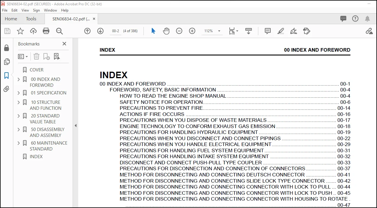
TABLE OF CONTENTS:
Komatsu 68E-88E Series Diesel Engine Shop Manual SEBM011501 – PDF DOWNLOAD
COVER……………………………………………………………………………………… 1
CONTENTS…………………………………………………………………………………… 2
1. SPECIFICATIONS AND PERFORMANCE…………………………………………………………….. 7
1.1 2D68E………………………………………………………………………………. 8
1.2 3D68E………………………………………………………………………………. 9
1.3 3D74E………………………………………………………………………………. 10
1.4 3D78AE……………………………………………………………………………… 11
1.5 3D82AE……………………………………………………………………………… 12
1.6 3D82E………………………………………………………………………………. 13
1.7 3D84E………………………………………………………………………………. 14
1.8 3D88E………………………………………………………………………………. 15
1.9 4D82E………………………………………………………………………………. 16
1.10 4D84E……………………………………………………………………………… 17
1.11 4D88E……………………………………………………………………………… 18
1.12 S3D84E…………………………………………………………………………….. 19
1.13 S4D84E…………………………………………………………………………….. 20
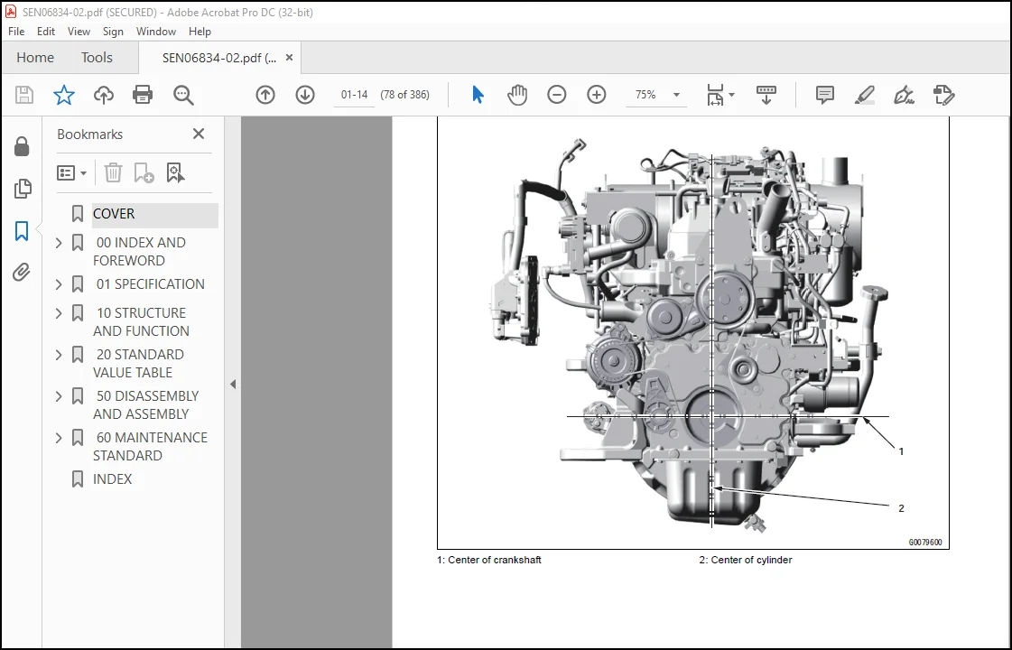
2. CROSS SECTIONAL VIEWS…………………………………………………………………….. 21
2.1 SPECIAL SWIRL PRE-COMBUSTION CHAMBER SYSTEM (INDIRECT INJECTION SYSTEM)……………………. 22
2.2 DIRECT INJECTION SYSTEM………………………………………………………………. 24
3. COOLING WATER, LUBRICATING OIL AND FUEL OIL…………………………………………………. 26
3.1 COOLING WATER……………………………………………………………………….. 27
3.2 LUBRICATING OIL……………………………………………………………………… 28
3.3 FUEL OIL……………………………………………………………………………. 30
4. TROUBLESHOOTING………………………………………………………………………….. 32
4.1 TROUBLE CAUSES AND REMEDIES…………………………………………………………… 33
4.2 TROUBLE DIAGNOSIS THROUGH MEASUREMENT OF COMPRESSION PRESSURE…………………………….. 37
5. SPECIAL SERVICE TOOLS AND MEASURING INSTRUMENTS……………………………………………… 38
5.1 SPECIAL SERVICE TOOLS………………………………………………………………… 39
5.2 MEASURING INSTRUMENTS………………………………………………………………… 42
6. MEASUREMENT, INSPECTION AND ADJUSTMENT……………………………………………………… 46
6.1 MEASURING THE COMPRESSION PRESSURE…………………………………………………….. 47
6.2 ADJUSTING THE VALVE HEAD CLEARANCE…………………………………………………….. 49
6.3 CHECKING THE V-BELT TENSION…………………………………………………………… 50
6.4 MEASURING AND CHECKING THE INJECTION PRESSURE AND SPRAY PATTERNS OF THE FUEL INJECTION VALVE…. 51
6.5 CHECKING AND ADJUSTING THE FUEL INJECTION TIMING………………………………………… 55
6.6 ADJUSTING THE NO-LOAD MAXIMUM (OR MINIMUM) REVOLUTIONS…………………………………… 58
6.7 CHECKING THE COOLING WATER SYSTEM AND RADIATOR FOR WATER LEAKAGE………………………….. 58
6.8 CHECKING THE BATTERY…………………………………………………………………. 59
6.9 CHECKING THE SENSORS…………………………………………………………………. 62
6.10 CHECKING THE OIL COOLER……………………………………………………………… 63
6.11 CHECKING THE PISTON COOLING NOZZLE……………………………………………………. 64
7. MEASURING PROCEDURES, SERVICE DATA AND CORRECTIVE ACTION……………………………………… 65
7.1 CYLINDER HEAD……………………………………………………………………….. 66
7.2 CYLINDER BLOCK………………………………………………………………………. 74
7.3 VALVE ROCKER ARM…………………………………………………………………….. 78
7.4 PISTON AND PISTON RING……………………………………………………………….. 81
7.5 CONNECTING ROD………………………………………………………………………. 87
7.6 CAMSHAFT……………………………………………………………………………. 92
7.7 CRANKSHAFT………………………………………………………………………….. 95
7.8 GEARS………………………………………………………………………………. 98
7.9 TROCHOID PUMP………………………………………………………………………..100
8. DISASSEMBLY AND REASSEMBLY…………………………………………………………………102
8.1 DISASSEMBLY………………………………………………………………………….103
8.2 PRECAUTIONS BEFORE AND DURING REASSEMBLY………………………………………………..108
9. SERVICE DATA……………………………………………………………………………..113
9.1 CYLINDER HEAD………………………………………………………………………..114
9.2 CYLINDER BLOCK……………………………………………………………………….115
9.3 VALVE ROCKER ARM……………………………………………………………………..115
9.4 PISTON………………………………………………………………………………116
9.5 PISTON RING………………………………………………………………………….117
9.6 CONNECTING ROD……………………………………………………………………….118
9.7 CAMSHAFT…………………………………………………………………………….118
9.8 CRANKSHAFT…………………………………………………………………………..119
9.9 SIDE GAP AND BACKLASH…………………………………………………………………119
9.10 OTHERS……………………………………………………………………………..120
10. TIGHTENING TORQUE………………………………………………………………………..121
10.1 MAIN BOLT/NUT……………………………………………………………………….122
10.2 STANDARD BOLT AND NUT………………………………………………………………..123
11. FUEL INJECTION PUMP FOR INDIRECT INJECTION SYSTEM……………………………………………124
11.1 EXPLODED VIEW (YPFR TYPE)…………………………………………………………….125
11.2 DISASSEMBLY…………………………………………………………………………126
11.3 INSPECTION………………………………………………………………………….128
11.4 REASSEMBLY………………………………………………………………………….130
12. FUEL INJECTION PUMP FOR DIRECT INJECTION SYSTEM……………………………………………..132
12.1 EXPLODED VIEW (YPES TYPE)…………………………………………………………….133
12.2 SPECIAL SERVICE TOOLS FOR DISASSEMBLY AND REASSEMBLY…………………………………….135
12.3 DISASSEMBLY…………………………………………………………………………136
12.4 INSPECTION………………………………………………………………………….141
12.5 REASSEMBLY………………………………………………………………………….143
13. GOVERNOR………………………………………………………………………………..148
13.1 EXPLODED VIEWS OF GOVERNOR FOR INDIRECT INJECTION SYSTEM…………………………………149
13.2 EXPLODED VIEWS OF GOVERNOR FOR DIRECT INJECTION SYSTEM…………………………………..151
13.3 DISASSEMBLY…………………………………………………………………………153
13.4 INSPECTION………………………………………………………………………….159
13.5 REASSEMBLY………………………………………………………………………….161
14. TURBOCHARGER…………………………………………………………………………….165
14.1 SPECIFICATIONS………………………………………………………………………166
14.2 CONSTRUCTION………………………………………………………………………..167
14.3 WASTE GATE VALVE ADJUSTING METHOD……………………………………………………..169
14.4 EXPLODED VIEW OF TURBOCHARGER (WITH WASTE GATE)…………………………………………171
14.5 TIGHTENING TORQUE……………………………………………………………………172
14.6 SERVICE STANDARDS……………………………………………………………………172
15. SERVICE INFORMATION FOR CARB ULG REGULATION…………………………………………………173
15.1 LIMITING THE HIGH IDLE AND LOW IDLE ADJUSTMENT SCREW…………………………………….174
15.2 LIMITING THE FUEL VOLUME LIMITER SCREW…………………………………………………175
16. ATTACHED DRAWING…………………………………………………………………………176
16.1 EXPLODED VIEWS OF ENGINE COMPONENTS……………………………………………………177
16.2 EXPLODED VIEWS OF ENGINE COMPONENTS……………………………………………………179
20. EPA CERTIFIED ENGINE……………………………………………………………………..181
20.1 APPLICABLE MACHINE, SERIAL NUMBER (EPA CERTIFIED ENGINE)…………………………………182
20.2 EPA CERTIFICATION PLATE ATTACHING LOCATION……………………………………………..183
20.3 DIFFERENCES WITH THE CURRENT PRODUCTION MODEL…………………………………………..184
20.4 FUEL INJECTION TIMING ADJUSTMENT………………………………………………………185
20.5 SECIFICATIONS……………………………………………………………………….196
Questions? Email us: [email protected]
PLEASE NOTE:
- This is the SAME MANUAL used by the dealerships to diagnose your vehicle
- No waiting for couriers / posts as this is a PDF manual and you can download it within 2 minutes time once you make the payment.
- Your payment is all safe and the delivery of the manual is INSTANT – You will be taken to the DOWNLOAD PAGE.
- So have no hesitations whatsoever and write to us about any queries you may have : heydownloadss @gmail.com
S.V


