Komatsu 6D105 Series Diesel Engine Shop Manual – PDF DOWNLOAD
Original price was: $43.95.$25.95Current price is: $25.95.
Komatsu 6D105 Series Diesel Engine Shop Manual
Book Code: SEBE61360109
Description
Komatsu 6D105 Series Diesel Engine Shop Manual
FILE DETAILS:
Komatsu 6D105 Series Diesel Engine Shop Manual
Brands: Komatsu
Equipment Type: Diesel Engine
Manuals Type: Shop Manual
Machine Model: 6D105 Series Diesel Engine
Book Code: SEBE61360109
Language: English
Pages: 350
File Format: Portable Document Format (PDF)
KOMATSU 6D105 SERIES DIESEL ENGINE SHOP MANUAL – PDF DOWNLOAD:
IMAGES PREVIEW OF THE MANUAL:
DESCRIPTION:
Komatsu 6D105 Series Diesel Engine Shop Manual
FOREWORD:
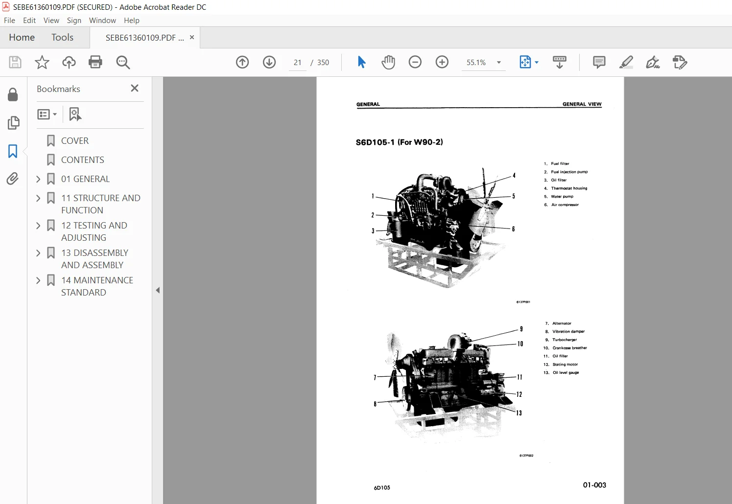
GENERAL:
- This shop manual has been prepared as an aid to improve the quality of repairs by giving the servicemen an accurate understanding of the product and by showing him the correct way to perform repairs and make judgements. Make sure you understand the contents of this manual and use it to full effect at every opportunity.
- This shop manual mainly contains the necessary technical information for operations performed in a service workshop. For ease of understanding, the manual is divided into the following chapters; these chapters are further divided into the each main group of components.
STRUCTURE AND FUNCTION:
This section explains the structure and function of each component. It serves not only to give an understanding of the structure, but also serves as reference material for troubleshooting.
TESTING AND ADJUSTING:
This section explains checks to be made before and after performing repairs, as well as adjustments to be made at completion of the checks and repairs. Troubleshooting charts correlating “Problems” to “Causes” are also included in thissection.
DISASSEMBLY AND ASSEMBLY:
This section explains the order to be followed when removing, installing, disassembling or assembling each component, as well as precautions to be taken for these operations.
MAINTENANCE STANDARD :
This section gives the judgement standards when inspecting disassembled parts.
TABLE OF CONTENTS:
Komatsu 6D105 Series Diesel Engine Shop Manual
COVER..........................................................................  1
CONTENTS.......................................................................  2
01 GENERAL..................................................................... 19
	GENERAL VIEW............................................................... 20
	SPECIFICATIONS............................................................. 22
	ASSEMBLY DRAWING........................................................... 32
	WEIGHT TABLE............................................................... 44
	PERFORMANCE CURVE.......................................................... 45
11 STRUCTURE AND FUNCTION...................................................... 75
	GENERAL STRUCTURE.......................................................... 76
	INTAKE AND EXHAUST SYSTEM.................................................. 80
		INTAKE AND EXHAUST SYSTEM CHART........................................ 80
		TURBOCHARGER........................................................... 89
	ENGINE BODY................................................................ 91
		CYLINDER HEAD.......................................................... 91
		MAIN CIRCULATION PART (1/3)............................................ 93
		MAIN CIRCULATION PART (2/3)............................................ 95
		MAIN CIRCULATION PART (3/3)............................................ 99
	LUBRICATING SYSTEM.........................................................101
		LUBRICATING SYSTEM CHART...............................................101
		OIL PUMP...............................................................104
		REGULATOR VALVE........................................................106
		OIL FILTER.............................................................106
		OIL COOLER.............................................................107
	FUEL SYSTEM................................................................109
		FUEL SYSTEM CHART......................................................109
		FOR CONSTRUCTION EQUIPMENT.............................................110
		FOR GENERATOR..........................................................112
		FUEL INJECTION PUMP....................................................114
		GOVERNOR...............................................................118
		FEED PUMP..............................................................122
		FUEL INJECTION NOZZLE..................................................124
		FUEL FILTER............................................................126
		FUEL CUT SOLENOID......................................................127
	COOLING SYSTEM.............................................................128
		COOLING SYSTEM CHART...................................................128
		WATER PUMP.............................................................135
		THERMOSTAT.............................................................138
		CORROSION RESISTOR.....................................................139
	ELECTRICAL SYSTEM..........................................................140
		WIRING DIAGRAM.........................................................140
		ALTERNATOR.............................................................141
		STARTING MOTOR.........................................................145
		SENSOR.................................................................148
	ACCESSORY..................................................................151
		AIR COMPRESSOR.........................................................151
12 TESTING AND ADJUSTING.......................................................153
	GENERAL OF TESTING AND ADJUSTING ..........................................154
		MEASURING ENGINE SPEED.................................................154
		CRANKING METHOD........................................................155
	INTAKE AND EXHAUST SYSTEM..................................................156
		CHECKING INTAKE AND EXHAUST SYSTEM.....................................156
		ADJUSTING VALVE CLEARANCE..............................................163
		MEASURING EXHAUST COLOR (BOSCH TYPE)...................................164
	ENGINE BODY................................................................165
		MEASURING BLOW-BY......................................................165
		MEASURING COMPRESSION PRESSURE.........................................166
		CLEANING BREATHER ELEMENT..............................................167
	LUBRICATING SYSTEM.........................................................168
		CHECKING LUBRICATING SYSTEM............................................168
		REPLACEMENT AND CLEANING OF LUBRICATING SYSTEM.........................176
		MEASURING OIL CONSUMPTION..............................................180
	FUEL SYSTEM................................................................182
		CHECKING FUEL SYSTEM...................................................182
		REPLACEMENT AND CLEANING OF COMPONENTS OF FUEL SYSTEM..................183
		CHECKING FUEL INJECTION PUMP...........................................185
		CHECKING AND ADJUSTMENT OF FUEL INJECTION NOZZLE.......................186
		TESTING AND ADJUSTING FUEL INJECTION TIMING ...........................188
		ADJUSTING FUEL CUT SOLENOID (FOR WA300-1)..............................190
		CALIBRATION DATA.......................................................191
	COOLING SYSTEM.............................................................217
		CHECKING COOLING SYSTEM................................................217
		REPLACEMENT AND CLEANING OF COMPONENTS OF COOLING SYSTEM...............220
		CHECKING THERMOSTAT FUNCTION...........................................226
		CHECKING AND ADJUSTMENT OF V-BELT TENSION AND REPLACEMENT OF V-BELT....227
	PERFORMANCE TEST...........................................................228
		TESTING METHOD OF PERFORMANCE..........................................228
		RUN-IN CRITERIA........................................................231
		PERFORMANCE TEST CRITERIA..............................................236
	TROUBLESHOOTING............................................................246
		TESTING AND ADJUSTING DATA.............................................247
		TESTING AND ADJUSTING TOOL LIST........................................250
		METHOD OF READING TROUBLESHOOTING TABLE................................251
		TROUBLESHOOTING TABLE..................................................253
			1. STARTING DEFECTIVE OR BADNESS...................................253
			2. ENGINE STOPPED DURING OPERATION.................................256
			3. ENGINE RUNS ABNORMALLY..........................................257
			4. FUEL CONSUMPTION TOO HIGH.......................................257
			5. LACK OF POWER...................................................258
			6. EXHAUST GAS IS BLACK............................................259
			7. EXHAUST GAS IS BLUE.............................................260
			8. OIL CONSUMPTION TOO HIGH........................................261
			9. OIL LEVEL RISES.................................................262
			10. OL QUICKLY BECOMES DIRTY.......................................263
			11. ENGINE OIL PRESSURE GAUGE INDICATOR FLUCTUATES ABNORMALLY......264
			12. LACK OF OIL PRESSURE...........................................265
			13. OIL IN COOLING SYSTEM..........................................266
			14. WATER TEMPERATURE DOES NOT RISE................................266
			15. WATER TEMPERATURE RISES EXCESSIVELY............................267
			16. TOO MUCH VIBRATION.............................................268
			17. ABNORMAL NOISE EMITTED.........................................269
			18. EXCESSIVE WEAR OF ENGINE PARTS.................................270
			19. ENGINE DOES NOT START BECAUSE OF FAULT IN ELECTRICAL SYSTEM....271
			20. BATTERY DOES NOT CHARGE........................................272
13 DISASSEMBLY AND ASSEMBLY....................................................273
	GENERAL....................................................................274
		DISASSEMBLY............................................................274
		ASSEMBLY...............................................................290
	DISASSEMBLY AND ASSEMBLY OF ACCESSORIES....................................315
		TURBOCHARGER...........................................................315
		OIL PUMP...............................................................323
		WATER PUMP.............................................................325
14 MAINTENANCE STANDARD........................................................329
	INTAKE AND EXHAUST SYSTEM..................................................330
		TURBOCHARGER...........................................................330
	ENGINE BODY................................................................331
		CYLINDER HEAD..........................................................331
		VALVES AND VALVE GUIDES................................................332
		ROCKER ARM SHAFT, PUSH-ROD AND TAPPET..................................334
		CYLINDER BLOCK.........................................................335
		CYLINDER LINER.........................................................337
		CRANKSHAFT.............................................................338
		CAMSHAFT...............................................................340
		TIMING GEAR............................................................341
		PISTON, PISTON RING, PISTON PIN........................................342
		CONNECTING ROD.........................................................344
		FLYWHEEL AND FLYWHEEL HOUSING..........................................345
	LUBRICATING SYSTEM.........................................................346
		OIL PUMP...............................................................346
	COOLING SYSTEM.............................................................350
		WATER PUMP, THERMOSTAT.................................................350
PLEASE NOTE:
- This is the SAME manual used by the dealers to troubleshoot any faults in your vehicle. This can be yours in 2 minutes after the payment is made.
- Contact us at [email protected] should you have any queries before your purchase or that you need any other service / repair / parts operators manual.


