Trusted Business
Verified & Licensed
Virus Free Files
100% Safe Downloads
Secure Payment
SSL Protected
Instant Delivery
Available Immediately
Sale!


KOMATSU 6D140-1 SERIES DIESEL ENGINE SERVICE REPAIR MANUAL (SEBE62120112) KOMATSU 6D140 1 – PDF DOWNLOAD
Original price was: $84.95.$26.95Current price is: $26.95.
- KOMATSU 6D140-1 SERIES DIESEL ENGINE SERVICE REPAIR MANUAL
- PUBLICATION NUMBER:SEBE62120112
Instant PDF Download
Available immediately
Save to Your Device
Download & keep forever
Antivirus Scanned
100% virus-free
Trusted Worldwide
175,000+ customers
Description
KOMATSU 6D140-1 SERIES DIESEL ENGINE SERVICE REPAIR MANUAL (SEBE62120112) KOMATSU 6D140 1
KOMATSU 6D140-1 SERIES DIESEL ENGINE SERVICE REPAIR MANUAL (SEBE62120112) KOMATSU 6D140 1 – PDF DOWNLOAD:
IMAGE PREVIEW:
DESCRIPTION:
KOMATSU 6D140-1 SERIES DIESEL ENGINE SERVICE REPAIR MANUAL (SEBE62120112) KOMATSU 6D140 1
- This shop manual has been prepared as an aid to improve the quality of repairs by giving the serviceman an accurate understanding of the product and by showing him the correct way to perform repairs and make judgements. Make sure you understand the contents of this manual and use it to full effect at every opportunity.
- This shop manual mainly contains the necessary technical information for operations performed in a service workshop. For ease of understanding, the manual is divided into the following chapters; these chapters are further divided into the each main group of components.
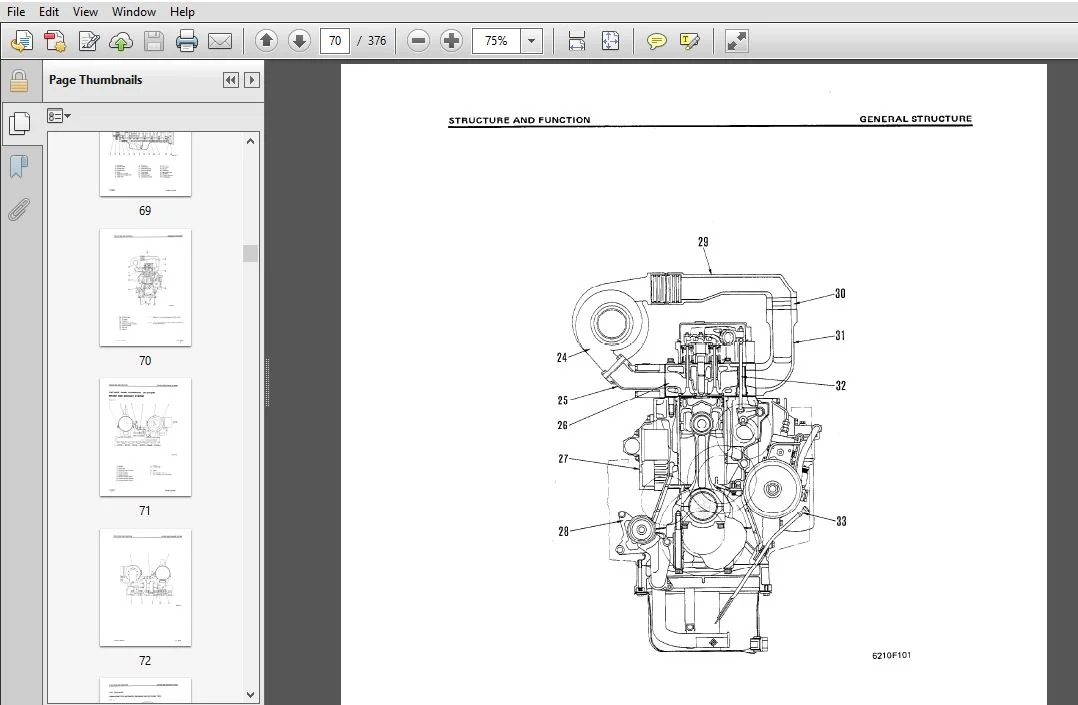
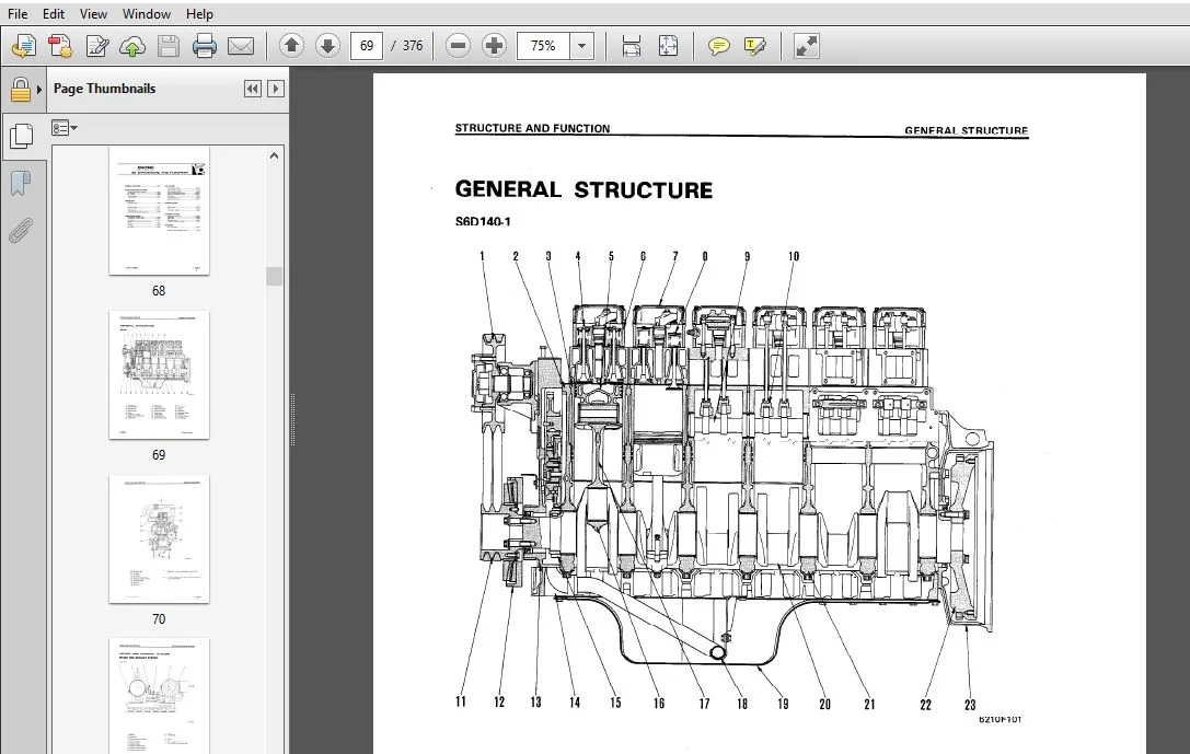
- STRUCTURE AND FUNCTION
This section explains the structure and function of each component. It serves not only to give an understanding of the structure, but also serves as reference material for troubleshooting. - TESTING AND ADJUSTING
This section explains checks to be made before and after performing repairs, as well as adjustments to be made at completion of the checks and repairs. Troubleshooting charts correlating “Problems” to “Causes“ are also included in this section. - DISASSEMBLY AND ASSEMBLY
This section explains the order to be followed when removing, installing, disassembling or assembling each component, as well as precautions to be taken for these operations. - MAINTENANCE STANDARD
This section gives the judgement standards when inspecting disassembled parts.
TABLE OF CONTENTS:
KOMATSU 6D140-1 SERIES DIESEL ENGINE SERVICE REPAIR MANUAL (SEBE62120112) KOMATSU 6D140 1
MAIN MENU..................................................................................  0
COVER......................................................................................  1
CONTENTS...................................................................................  2
SAFETY.....................................................................................  6
	SAFETY NOTICE..........................................................................  6
01 GENERAL................................................................................. 24
	GENERAL VIEW .......................................................................... 25
	SPECIFICATIONS ........................................................................ 27
	GENERAL ASSEMBLY DRAWING .............................................................. 37
	ENGINE PERFORMANCE CURVE .............................................................. 49
	WEIGHT TABLE .......................................................................... 67
11 STRUCTURE AND FUNCTION.................................................................. 68
	GENERAL STRUCTURE...................................................................... 69
	INTAKE AND EXHAUST SYSTEM ............................................................. 71
		INTAKE AND EXHAUST SYSTEM.......................................................... 71
		AIR CLEANER ....................................................................... 73
		TURBOCHARGER ...................................................................... 76
		AFTER-COOLER ...................................................................... 78
	ENGINE BODY............................................................................ 79
		CYLINDER HEAD ..................................................................... 79
		VALVE SYSTEM ...................................................................... 83
		CYLINDER BLOCK .................................................................... 87
		MAIN CIRCULATION SYSTEM ........................................................... 89
		TIMING GEAR ....................................................................... 91
		FLYWHEEL AND FLYWHEEL HOUSING ..................................................... 93
	LUBRICATION SYSTEM..................................................................... 95
		LUBRICATION SYSTEM CHART .......................................................... 95
		OIL PUMP .......................................................................... 98
		REGULATOR VALVE AND PISTON COOLING VALVE .......................................... 99
		OIL FILTER ........................................................................101
		OIL COOLER ........................................................................104
	FUEL SYSTEM............................................................................106
		FUEL SYSTEM CHART .................................................................106
		FUEL INJECTION PUMP ...............................................................107
		FUEL INJECTION NOZZLE  ............................................................111
		BOOST COMPENSATOR DEVICE ..........................................................112
		FUEL FILTER .......................................................................114
		FUEL SOLENOID .....................................................................115
		ENGINE STOP MOTOR .................................................................117
	COOLING SYSTEM.........................................................................123
		COOLING SYSTEM CHART ..............................................................123
		WATER PUMP ........................................................................124
		THERMOSTAT ........................................................................127
		CORROSION RESISTOR ................................................................129
	ELECTRICAL SYSTEM......................................................................131
		ALTERNATOR MOUNTING ...............................................................131
		ALTERNATOR ........................................................................132
		STARTING MOTOR ....................................................................135
		ELECTRICAL INTAKE AIR HEATER ......................................................136
	ACCESSORY..............................................................................137
		AIR COMPRESSOR ....................................................................137
		EXHAUST BRAKE......................................................................139
		EXHAUST BRAKE BUTTERFLY VALVE .....................................................140
12 TESTING AND ADJUSTING...................................................................142
	ENGINE BODY............................................................................143
		ADJUSTING VALVE CLEARANCE .........................................................143
		MEASURING COMPRESSION PRESSURE ....................................................144
	FUEL SYSTEM............................................................................145
		CHECKING AND ADJUSTING FUEL  INJECTION  TIMING ....................................145
		ADJUSTING FUEL INJECTION PRESSURE .................................................147
		ADJUSTING FUEL CUT SOLENOID .......................................................148
	COOLING SYSTEM.........................................................................152
		CHECKING AND ADJUSTING  V-BELT TENSION ............................................152
	FUEL INJECTION PUMP CALIBRATION DATA ..................................................154
	PERFORMANCE TEST.......................................................................213
		RUN-IN STANDARD....................................................................213
		PERFORMANCE TEST CRITERIA .........................................................217
		TESTING AND ADJUSTING TOOL LIST ...................................................223
		TESTING AND ADJUSTING DATA ........................................................225
	TROUBLESHOOTING .......................................................................235
		POINTS TO REMEMBER WHEN TROUBLESHOOTING............................................237
		METHOD OF USING TROUBLESHOOTING CHART..............................................238
		TROUBLESHOOTING TABLE .............................................................242
		S-1 Starting performance is poor (Starting always takes time) .....................242
		S-2 Engine does not start .........................................................243
			1. Engine does not turn .......................................................243
			2. Engine turns but no exhaust gas comes out (Fuel is not being injected)......244
			3. Exhaust gas comes out but engine does not start (Fuel is being injected)....245
		S-3 Engine does not pick up smoothly (Follow-up is poor) ..........................246
		S-4 Engine stops during operations ................................................247
		S-5 Engine does not rotate smoothly (hunting) .....................................248
		S-6 Engine lacks output (no power) ................................................249
		S-7 Exhaust gas is black (incomplete combustion) ..................................250
		S-8 Oil consumption is excessive (or exhaust gas is blue)..........................251
		S-9 Oil becomes contaminated quickly ..............................................252
		S-10 Fuel consumption is excessive ................................................253
		S-11 Oil is in cooling water, or water spurts back, or water level goes down ......254
		S-12 Oil pressure lamp lights up (drop in oil pressure) ...........................255
		S-13 Oil level rises...............................................................256
		S-14 Water temperature becomes too high (overheating) .............................257
		S-15 Abnormal noise is made .......................................................258
		S-16 Vibration is excessive .......................................................259
13 DISASSEMBLY AND ASSEMBLY................................................................261
	GENERAL ...............................................................................262
		DISASSEMBLY........................................................................262
		ASSEMBLY ..........................................................................282
	TURBOCHARGER ..........................................................................314
		DISASSEMBLY........................................................................314
		ASSEMBLY...........................................................................318
	EXHAUST BRAKE .........................................................................322
		DISASSEMBLY AND ASSEMBLY...........................................................322
14 MAINTENANCE STANDARD....................................................................327
	INTAKE AND EXHAUST SYSTEM..............................................................328
		TURBOCHARGER ......................................................................328
	ENGINE BODY............................................................................331
		CYLINDER HEAD .....................................................................331
		VALVE, VALVE SPRING AND VALVE GUIDE ...............................................332
		ROCKER ARM AND SHAFT ..............................................................334
		CROSSHEAD AND GUIDE ...............................................................335
		CYLINDER BLOCK ....................................................................336
		CYLINDER LINER ....................................................................337
		CRANKSHAFT ........................................................................338
		CAMSHAFT...........................................................................339
		CAM FOLLOWER AND PUSH ROD .........................................................340
		CONNECTING ROD ....................................................................341
		PISTON, PISTON RING AND PISTON PIN ................................................342
		TIMING GEAR .......................................................................344
		FLYWHEEL AND FLYWHEEL HOUSING .....................................................346
	LUBRICATION SYSTEM.....................................................................348
		OIL PUMP AND MAIN RELIEF VALVE ....................................................348
		REGULATOR VALVE AND SAFETY VALVE ..................................................350
		OIL COOLER ........................................................................351
	COOLING SYSTEM.........................................................................353
		WATER PUMP ........................................................................353
		THERMOSTAT ........................................................................355
15 REPAIR AND REPLACEMENT OF PARTS.........................................................357
	CYLINDER HEAD..........................................................................358
		GRINDING CYLINDER HEAD MOUNTING FACE ..............................................358
		REPLACING VALVE SEAT INSERT .......................................................360
		REPLACING CROSSHEAD GUIDE .........................................................365
		REPLACING VALVE GUIDE .............................................................366
		GRINDING VALVE ....................................................................367
		PRESSURE TEST .....................................................................368
	CYLINDER BLOCK.........................................................................369
		REPLACING CAM BUSHING .............................................................369
		REPLACING CRANKSHAFT GEAR .........................................................371
		REPLACING CAM GEAR ................................................................372
		REPLACING FLYWHEEL RING GEAR ......................................................373
		REPLACING CONNECTING ROD SMALL  BUSHING ...........................................374
PLEASE NOTE:
⦁ This is not a physical manual but a digital manual – meaning no physical copy will be couriered to you. The manual can be yours in the next 2 mins as once you make the payment, you will be directed to the download page IMMEDIATELY.
⦁ This is the same manual used by the dealers inorder to diagnose your vehicle of its faults.
⦁ Require some other service manual or have any queries: please WRITE to us at [email protected]


