
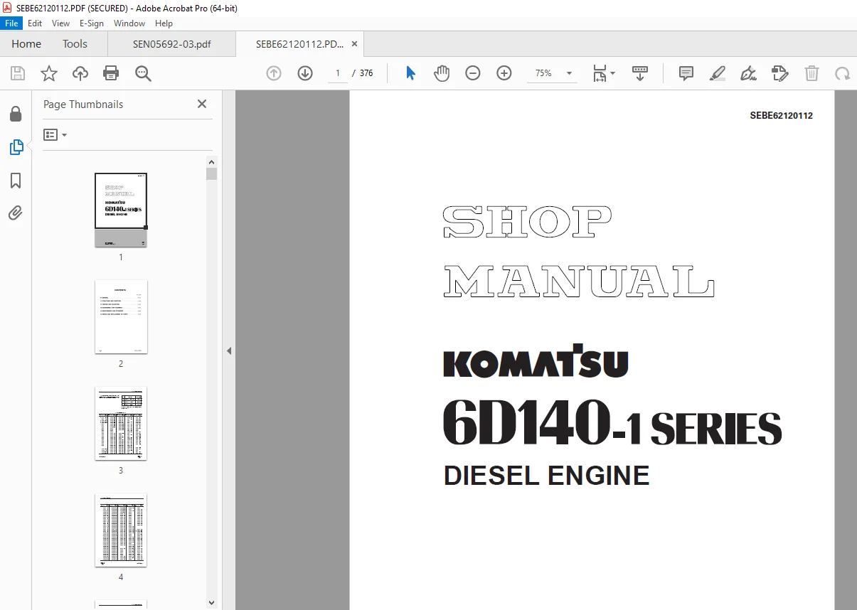
Komatsu 6D140-1 Series Diesel Engine Shop Manual SEBE62120112 PDF
$28.95
Komatsu 6D140-1 Series Diesel Engine Shop Manual SEBE62120112 – PDF DOWNLOAD
Description
Komatsu 6D140-1 Series Diesel Engine Shop Manual SEBE62120112 – PDF DOWNLOAD
FILE DETAILS:
Komatsu 6D140-1 Series Diesel Engine Shop Manual SEBE62120112 – PDF DOWNLOAD
Language : English
Pages : 376
Downloadable : Yes
File Type : PDF
IMAGES PREVIEW OF THE MANUAL:
TABLE OF CONTENTS:
Komatsu 6D140-1 Series Diesel Engine Shop Manual SEBE62120112 – PDF DOWNLOAD
MAIN MENU 0
COVER 1
CONTENTS 2
SAFETY 6
SAFETY NOTICE 6
01 GENERAL 24
GENERAL VIEW 25
SPECIFICATIONS 27
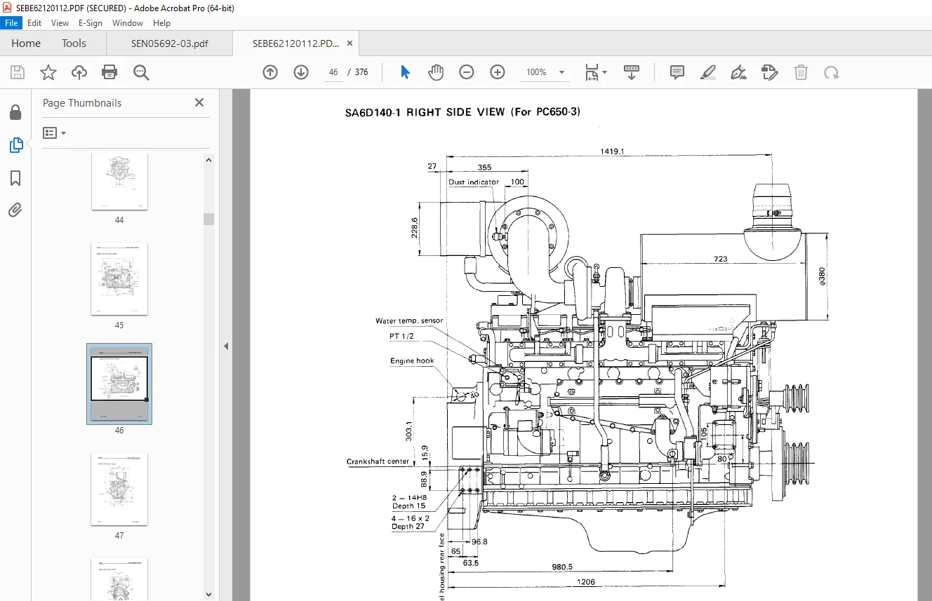
GENERAL ASSEMBLY DRAWING 37
ENGINE PERFORMANCE CURVE 49
WEIGHT TABLE 67
11 STRUCTURE AND FUNCTION 68
GENERAL STRUCTURE 69
INTAKE AND EXHAUST SYSTEM 71
INTAKE AND EXHAUST SYSTEM 71
AIR CLEANER 73
TURBOCHARGER 76
AFTER-COOLER 78
ENGINE BODY 79
CYLINDER HEAD 79
VALVE SYSTEM 83
CYLINDER BLOCK 87
MAIN CIRCULATION SYSTEM 89
TIMING GEAR 91
FLYWHEEL AND FLYWHEEL HOUSING 93
LUBRICATION SYSTEM 95
LUBRICATION SYSTEM CHART 95
OIL PUMP 98
REGULATOR VALVE AND PISTON COOLING VALVE 99
OIL FILTER 101
OIL COOLER 104
FUEL SYSTEM 106
FUEL SYSTEM CHART 106
FUEL INJECTION PUMP 107
FUEL INJECTION NOZZLE 111
BOOST COMPENSATOR DEVICE 112
FUEL FILTER 114
FUEL SOLENOID 115
ENGINE STOP MOTOR 117
COOLING SYSTEM 123
COOLING SYSTEM CHART 123
WATER PUMP 124
THERMOSTAT 127
CORROSION RESISTOR 129
ELECTRICAL SYSTEM 131
ALTERNATOR MOUNTING 131
ALTERNATOR 132
STARTING MOTOR 135
ELECTRICAL INTAKE AIR HEATER 136
ACCESSORY 137
AIR COMPRESSOR 137
EXHAUST BRAKE 139
EXHAUST BRAKE BUTTERFLY VALVE 140
12 TESTING AND ADJUSTING 142
ENGINE BODY 143
ADJUSTING VALVE CLEARANCE 143
MEASURING COMPRESSION PRESSURE 144
FUEL SYSTEM 145
CHECKING AND ADJUSTING FUEL INJECTION TIMING 145
ADJUSTING FUEL INJECTION PRESSURE 147
ADJUSTING FUEL CUT SOLENOID 148
COOLING SYSTEM 152
CHECKING AND ADJUSTING V-BELT TENSION 152
FUEL INJECTION PUMP CALIBRATION DATA 154
PERFORMANCE TEST 213
RUN-IN STANDARD 213
PERFORMANCE TEST CRITERIA 217
TESTING AND ADJUSTING TOOL LIST 223
TESTING AND ADJUSTING DATA 225
TROUBLESHOOTING 235
POINTS TO REMEMBER WHEN TROUBLESHOOTING 237
METHOD OF USING TROUBLESHOOTING CHART 238
TROUBLESHOOTING TABLE 242
S-1 Starting performance is poor (Starting always takes time) 242
S-2 Engine does not start 243
1 Engine does not turn 243
2 Engine turns but no exhaust gas comes out (Fuel is not being injected) 244
3 Exhaust gas comes out but engine does not start (Fuel is being injected) 245
S-3 Engine does not pick up smoothly (Follow-up is poor) 246
S-4 Engine stops during operations 247
S-5 Engine does not rotate smoothly (hunting) 248
S-6 Engine lacks output (no power) 249
S-7 Exhaust gas is black (incomplete combustion) 250
S-8 Oil consumption is excessive (or exhaust gas is blue) 251
S-9 Oil becomes contaminated quickly 252
S-10 Fuel consumption is excessive 253
S-11 Oil is in cooling water, or water spurts back, or water level goes down 254
S-12 Oil pressure lamp lights up (drop in oil pressure) 255
S-13 Oil level rises 256
S-14 Water temperature becomes too high (overheating) 257
S-15 Abnormal noise is made 258
S-16 Vibration is excessive 259
13 DISASSEMBLY AND ASSEMBLY 261
GENERAL 262
DISASSEMBLY 262
ASSEMBLY 282
TURBOCHARGER 314
DISASSEMBLY 314
ASSEMBLY 318
EXHAUST BRAKE 322
DISASSEMBLY AND ASSEMBLY 322
14 MAINTENANCE STANDARD 327
INTAKE AND EXHAUST SYSTEM 328
TURBOCHARGER 328
ENGINE BODY 331
CYLINDER HEAD 331
VALVE, VALVE SPRING AND VALVE GUIDE 332
ROCKER ARM AND SHAFT 334
CROSSHEAD AND GUIDE 335
CYLINDER BLOCK 336
CYLINDER LINER 337
CRANKSHAFT 338
CAMSHAFT 339
CAM FOLLOWER AND PUSH ROD 340
CONNECTING ROD 341
PISTON, PISTON RING AND PISTON PIN 342
TIMING GEAR 344
FLYWHEEL AND FLYWHEEL HOUSING 346
LUBRICATION SYSTEM 348
OIL PUMP AND MAIN RELIEF VALVE 348
REGULATOR VALVE AND SAFETY VALVE 350
OIL COOLER 351
COOLING SYSTEM 353
WATER PUMP 353
THERMOSTAT 355
15 REPAIR AND REPLACEMENT OF PARTS 357
CYLINDER HEAD 358
GRINDING CYLINDER HEAD MOUNTING FACE 358
REPLACING VALVE SEAT INSERT 360
REPLACING CROSSHEAD GUIDE 365
REPLACING VALVE GUIDE 366
GRINDING VALVE 367
PRESSURE TEST 368
CYLINDER BLOCK 369
REPLACING CAM BUSHING 369
REPLACING CRANKSHAFT GEAR 371
REPLACING CAM GEAR 372
REPLACING FLYWHEEL RING GEAR 373
REPLACING CONNECTING ROD SMALL BUSHING 374
DESCRIPTION:
Komatsu 6D140-1 Series Diesel Engine Shop Manual SEBE62120112 – PDF DOWNLOAD
Mistakes in operation are extremely dangerous. Read the Operation and Maintenance Manual carefully BEFORE operating the machine.
1. Before carrying out any greasing or repairs, read all the precautions given on the decals which are fixed to the machine.
2. When carrying out any operation, always wear safety shoes and helmet. Do not wear loose work clothes, or clothes with buttons missing.
• Always wear safety glasses when hitting parts with a hammer.
Always wear safety glasses when grinding parts with a grinder, etc.
3. If welding repairs are needed, always have a trained, experienced welder carry out the work. When carrying out welding work, always wear welding gloves, apron, glasses, cap and other clothes suited for welding work.
4. When carrying out any operation with two or more workers, always agree on the operating procedure before starting. Always inform your fellow workers before starting any step of the operation. Before starting work, hang UNDER REPAIR signs on the controls in the operator’s compartment.
5. Keep all tools in good condition and learn the correct way to use them.
PREPARATIONS FOR WORK:
7. Before adding oil or making any repairs, park the machine on hard, level ground, and block the wheels or tracks to prevent the machine from moving.
8. Before starting work, lower blade, ripper, bucket or any other work equipment to the ground. If this is not possible, insert the safety pin or use blocks to prevent the work equipment from falling. In addition, be sure to lock all the control levers and hang warning signs on them.
9. When disassembling or assembling, sup- port the machine with blocks, jacks or stands before starting work.
10. Remove all mud and oil from the steps or other places used to get on and off the machine. Always use the handrails, ladders or steps when getting on or off the machine. Never jump on or off the machine. If it is impossible to use the handrails, ladders or steps, use a stand to provide safe footing.
11. When removing the oil filler cap, drain plug or hydraulic pressure measuring plugs, loosen them slowly to prevent the oil from spurting out.
Before disconnecting or removing components of the oil, water or air circuits, first remove the pressure completely from the circuit.
12. The water and oil in the circuits are hot when the engine is stopped, so be careful not to get burned.
Wait for the oil and water to cool before carrying out any work on the oil or water circuits.
13. Before starting work, remove the leads from the battery. Always remove the lead from the negative (-) terminal first.
14. When raising heavy components, use a hoist or crane.
Check that the wire rope, chains and hooks are free from damage.
Always use lifting equipment which has ample capacity.
Install the lifting equipment at the correct places. Use a hoist or crane and operate slowly to prevent the component from hit- ting any other part. Do not work with any part still raised by the hoist or crane.
15. When removing covers which are under internal pressure or under pressure from a spring, always leave two bolts in position on opposite sides. Slowly release the pressure, then slowly loosen the bolts to remove.
16. When removing components, be careful not to break or damage the wiring. Damaged wiring may cause electrical fires.
17. When removing piping, stop the fuel or oil from spilling out. If any fuel or oil drips on to the floor, wipe it up immediately. Fuel or oil on the floor can cause you to slip, or can even start fires.
G.B 18/12/24



