Komatsu 6D170-1 Series Diesel Engine Shop Manual SEBES6161000 – PDF DOWNLOAD
Original price was: $89.95.$27.95Current price is: $27.95.
Komatsu 6D170-1 Series Diesel Engine Shop Manual SEBES6161000 – PDF DOWNLOAD
APPLICABLE
ENGINE MODELS
S6D170-1
SA6D170-В-1
SA6D170-А-1
Description
Komatsu 6D170-1 Series Diesel Engine Shop Manual SEBES6161000 – PDF DOWNLOAD
IMAGES PREVIEW OF THE MANUAL:
DESCRIPTION:
Komatsu 6D170-1 Series Diesel Engine Shop Manual SEBES6161000 – PDF DOWNLOAD
APPLICABLE
ENGINE MODELS
S6D170-1
SA6D170-В-1
SA6D170-А-1
FOREWORD:
This shop manual has been prepared as an aid to improve the quality of repairs by giving the operator an accurate
understanding of the product and by showing him the correct way to perform repairs and make judgements. Make sure
you understand the contents of this manual and use it to full effect at every opportunity.
This shop manual mainly contains the necessary technical information for operations performed in a service workshop.
The manual is divided into chapters on each main group of components; these chapters are further divided into the
following sections.
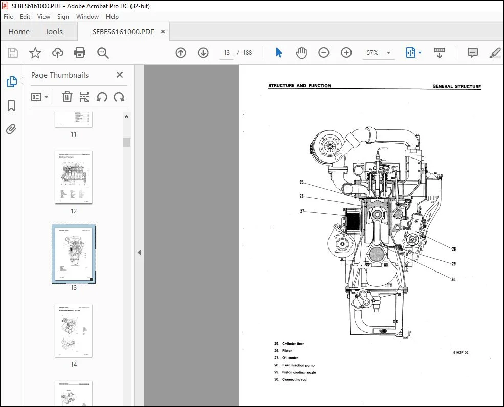
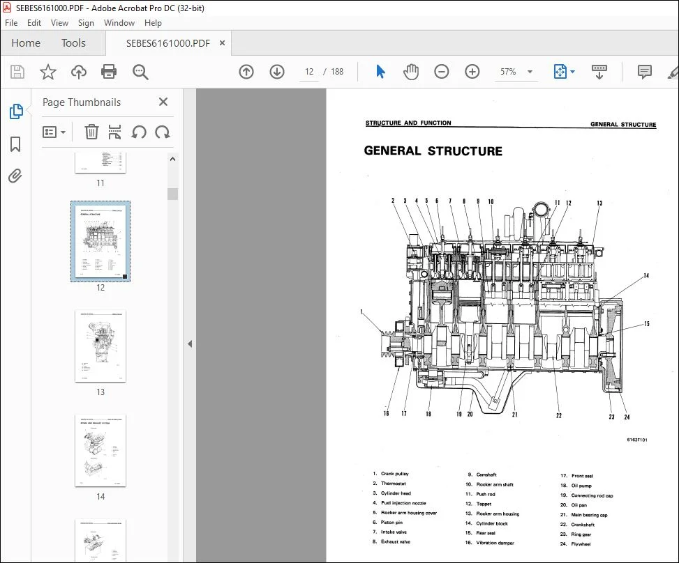
STRUCTURE AND FUNCTION
This section explains the structure and function of each component. It serves not only to give an understanding
of the structure, but also serves as reference material for troubleshooting.
TESTING AND ADJUSTMENTS
This sections explains checks to be made before and after performing repairs, as well as adjustments to be
made at completion of the checks and repairs.
Troubleshooting charts correlating «Problems» to «Causes» are also included in this section.
REMOVAL AND INSTALLATION
This section explains the order to be followed when removing, installing, disassembling or assembling each
component, as well as precautions to be taken for these operations.
STANDARD MAINTENANCE
This section gives the judgement standards when inspecting disassembled parts.
TABLE OF CONTENTS:
Komatsu 6D170-1 Series Diesel Engine Shop Manual SEBES6161000 – PDF DOWNLOAD
COVER 1
CONTENTS 2
11 STRUCTURE AND FUNCTION 11
GENERAL STRUCTURE 12
INTAKE AND EXHAUST SYSTEM 14
INTAKE AND EXHAUST SYSTEM 14
TURBOCHARGER 21
AFTER-COOLER 25
ENGINE BODY 26
CYLINDER HEAD 26
VALVE SYSTEM 28
CYLINDER BLOCK 30
MAIN CIRCULATION PART 32
TIMING GEAR 34
FLYWHEEL AND FLYWHEEL HOUSING 36
LUBRICATION SYSTEM 37
LUBRICATION SYSTEM CHART 37
OIL PUMP 38
OIL FILTER AND SAFETY VALVE 39
OIL COOLER 40
MAIN RELIEF VALVE 42
OIL COOLER BY-PASS VALVE 42
PISTON COOLING VALVE 43
MECHANICAL PUMP 44
FUEL SYSTEM 45
FUEL SYSTEM CHART 45
FUEL INJECTION PUMP 46
FUEL INJECTION NOZZLE 50
FUEL INJECTION PUMP DRIVE 51
FUEL FILTER 52
FUEL SOLENOID 53
ENGINE STOP MOTOR 55
STARTING AID 60
COOLING SYSTEM 61
COOLING SYSTEM CHART 61
WATER PUMP 62
FAN DRIVE AND TENSION PULLEY 63
CORROSION RESISTOR 67
THERMOSTAT 68
ACCESSORY 69
AIR COMPRESSOR MOUNTING 69
AIR COMPRESSOR 70
ELECTRICAL SYSTEM 71
ALTERNATOR 71
STARTING MOTOR 73
12 TESTING AND ADJUSTING 74
FUEL SYSTEM 75
ADJUSTING FUEL SOLENOID 75
ADJUSTING ENGINE STOP MOTOR 76
ADJUSTING FUEL INJECTION PRESSURE 77
TESTING AND ADJUSTING TOOL LIST 80
TROUBLESHOOTING 81
METHOD OF READING TROUBLESHOOTING TABLE 82
TROUBLESHOOTING TABLE 84
1 STARTING DEFECTIVE OR BADNESS 84
2 ENGINE STOPPED DURING OPERATION 87
3 ENGINE RUNS ABNORMALLY 88
4 FUEL CONSUMPTION TOO HIGH 88
5 LACK OF POWER 89
6 EXHAUST GAS IS BLACK 90
7 EXHAUST GAS IS BLUE 91
8 OIL CONSUMPTION TOO HIGH 92
9 OIL LEVEL RISES 93
10 OIL QUICKLY BECOMES DIRTY 94
11 ENGINE OIL PRESSURE GAUGE INDICATOR FLUCTUATES ABNORMALLY 95
12 LACK OF OIL PRESSURE 96
13 OIL IN COOLING SYSTEM 97
14 WATER TEMPERATURE DOES NOT RISE 97
15 WATER TEMPERATURE RISES EXCESSIVELY 98
16 TOO MUCH VIBRATION 99
17 ABNORMAL NOISE EMITTED 100
18 EXCESSIVE WEAR OF ENGINE PARTS 101
19 ENGINE DOES NOT START BECAUSE OF FAULT IN ELECTRICAL SYSTEM 102
20 BATTERY DOES NOT CHARGE 103
13 DISASSEMBLY AND ASSEMBLY 104
GENERAL 106
DISASSEMBLY 106
ASSEMBLY 124
14 MAINTENANCE STANDARD 148
TURBOCHARGER 149
CYLINDER HEAD 153
VALVES AND VALVE GUIDE 154
CROSSHEAD AND CROSSHEAD GUIDE 155
PUSH ROD AND CAM FOLLOWER 156
CYLINDER BLOCK 157
CYLINDER LINER 159
CRANKSHAFT 160
CAMSHAFT 161
TIMING GEAR 162
PISTON, PISTON RING AND PISTON PIN 163
CONNECTING ROD 164
OIL PUMP 165
OIL PUMP RELIEF VALVE, PISTON COOLING VALVE AND OIL COOLER BY-PASS VALVE 166
AIR COMPRESSOR 167
WATER PUMP 169
15 REPAIR AND REPLACEMENT OF PARTS 170
REPAIRING MOUNTING FACE OF CYLINDER HEAD BY GRINDING 171
REPLACING VALVE SEAT INSERTS 172
REPLACING NOZZLE HOLDER SLEEVE 176
REPLACING VALVE GUIDE 179
REPLACING CROSS HEAD GUIDE 180
GRINDING THE VALVE 180
GRINDING THE TOP SURFACE OF CYLINDER BLOCK 181
REPLACING MAIN METAL CAP 182
REPAIRING THE CRANKSHAFT 183
REPLACING CAM BUSHING 187
REPLACING CRANK GEAR 188
REPLACING CAM GEAR 188
REPLACING FLYWHEEL RING GEAR 188
Questions? Email us: [email protected]
PLEASE NOTE:
- This is the SAME exact manual used by your dealers to fix your vehicle.
- The same can be yours in the next 2-3 mins as you will be directed to the download page immediately after paying for the manual.
- Any queries / doubts regarding your purchase, please feel free to contact [email protected]
S.V


