Komatsu 6D170-2 Series Diesel Engine Shop Manual SEBM008107 – PDF DOWNLOAD
Original price was: $89.95.$29.95Current price is: $29.95.
Komatsu 6D170-2 Series Diesel Engine Shop Manual SEBM008107 – PDF DOWNLOAD
Description
Komatsu 6D170-2 Series Diesel Engine Shop Manual SEBM008107 – PDF DOWNLOAD
FILE DETAILS:
Komatsu 6D170-2 Series Diesel Engine Shop Manual SEBM008107 – PDF DOWNLOAD
Language : English
Pages : 341
Downloadable : Yes
File Type : PDF
Size: 15.6 MB
IMAGES PREVIEW OF THE MANUAL:
DESCRIPTION:
Komatsu 6D170-2 Series Diesel Engine Shop Manual SEBM008107 – PDF DOWNLOAD
The Komatsu 6D170-2 Series Diesel Engine Shop Manual SEBM008107 is a comprehensive guide that provides detailed information on the service, repair, and maintenance of the 6D170-2 Series diesel engine. This engine is a six-cylinder, turbocharged engine that is commonly used in heavy construction equipment, such as bulldozers, excavators, and dump trucks.
The manual is published by Komatsu, a leading manufacturer of heavy equipment and construction machinery. The manual is designed to be used by mechanics and technicians who are responsible for maintaining and repairing Komatsu equipment. It is an essential tool for anyone who works with Komatsu engines.
The manual is divided into several sections, each of which provides specific information on different aspects of the engine. The sections include:
- General information: This section provides an overview of the engine, including its specifications, features, and operating principles. It also includes information on safety precautions, tools, and equipment needed for maintenance and repair.
- Inspection and adjustment: This section provides detailed instructions on how to inspect and adjust various components of the engine, including the cylinder head, valves, fuel system, and cooling system.
- Engine disassembly and assembly: This section provides step-by-step instructions on how to disassemble and assemble the engine. It includes detailed diagrams and illustrations to help users understand each step of the process.
- Troubleshooting: This section provides a comprehensive list of potential problems that may arise with the engine, along with diagnostic procedures to help identify and fix these issues.
- Maintenance: This section provides information on the regular maintenance tasks that should be performed on the engine, including oil changes, filter replacements, and other routine tasks.
- Reassembly and testing: This section provides detailed instructions on how to reassemble the engine after repairs have been made. It also includes information on how to test the engine to ensure that it is functioning properly.
- Service data: This section provides detailed technical data on the engine, including torque specifications, compression pressures, and other important information.
The manual is written in clear, concise language, and is filled with detailed diagrams and illustrations to help users understand each step of the process. It is an essential tool for anyone who works with Komatsu engines, and can help to ensure that the engine is maintained and repaired to the highest standards. It is important to note that the manual is designed for use by qualified mechanics and technicians, and should not be used by individuals without the appropriate training and experience.
TABLE OF CONTENTS:
Komatsu 6D170-2 Series Diesel Engine Shop Manual SEBM008107 – PDF DOWNLOAD
COVER…………………………………………………………………………… 1
CONTENTS………………………………………………………………………… 2
01 GENERAL………………………………………………………………………. 25
APPLICABLE MACHINE……………………………………………………………. 26
SPECIFICATIONS……………………………………………………………….. 27
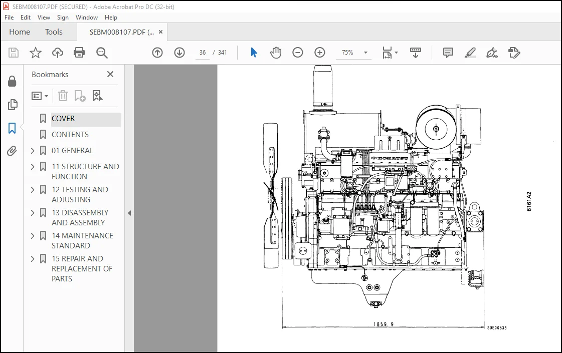
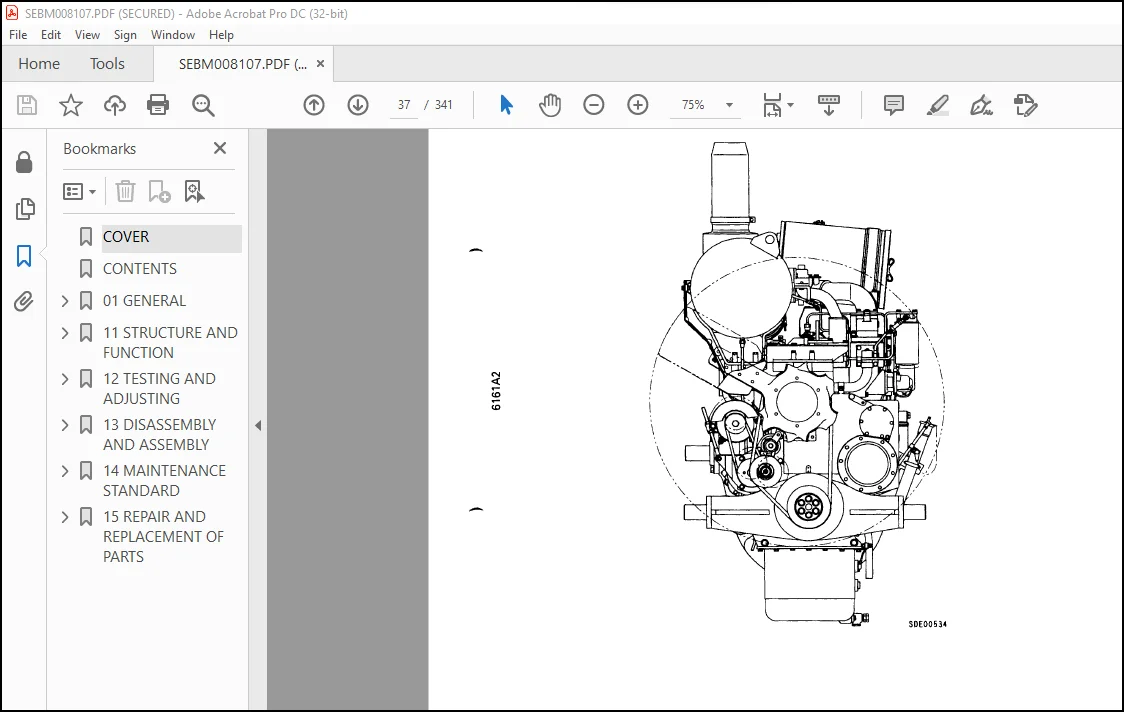
GENERAL ASSEMBLY DRAWING………………………………………………………. 31
WEIGHT TABLE…………………………………………………………………. 54
ENGINE PERFORMANCE CURVE………………………………………………………. 55
11 STRUCTURE AND FUNCTION…………………………………………………………. 64
INTAKE AND EXHAUST SYSTEM……………………………………………………… 65
AIR CLEANER………………………………………………………………. 65
TURBOCHARGER……………………………………………………………… 67
AFTERCOOLER………………………………………………………………. 71
ENGINE BODY………………………………………………………………….. 73
CYLINDER HEAD…………………………………………………………….. 73
VALVE SYSTEM……………………………………………………………… 75
CYLINDER BLOCK……………………………………………………………. 77
MAIN REVOLUTION…………………………………………………………… 79
TIMING GEAR………………………………………………………………. 81
FLYWHEEL AND FLYWHEEL HOUSING………………………………………………. 83
LUBRICATION SYSTEM……………………………………………………………. 84
OIL PUMP…………………………………………………………………. 85
OIL FILTER AND SAFETY VALVE………………………………………………… 86
BYPASS OIL FILTER…………………………………………………………. 87
OIL COOLER……………………………………………………………….. 88
OIL PUMP RELIEF VALVE……………………………………………………… 89
OIL COOLER BYPASS VALVE……………………………………………………. 89
PISTON COOLING VALVE………………………………………………………. 90
FUEL SYSTEM………………………………………………………………….. 91
FUEL INJECTION PUMP……………………………………………………….. 94
FUEL INJECTION PUMP……………………………………………………….. 97
FUEL INJECTION NOZZLE………………………………………………………100
FUEL INJECTION PUMP DRIVE…………………………………………………..101
FUEL FILTER……………………………………………………………….103
STARTING AID………………………………………………………………105
FUEL CUT SOLENOID………………………………………………………….106
ENGINE STOP MOTOR………………………………………………………….108
COOLING SYSTEM………………………………………………………………..113
WATER PUMP………………………………………………………………..114
COOLING FAN……………………………………………………………….115
CORROSION RESISTOR…………………………………………………………122
THERMOSTAT………………………………………………………………..123
ACCESSORY…………………………………………………………………….124
AIR COMPRESSOR MOUNTING…………………………………………………….124
FREON COMPRESSOR…………………………………………………………..126
AIR COMPRESSOR…………………………………………………………….127
EXHAUST BRAKE……………………………………………………………..129
ELECTRICAL SYSTEM……………………………………………………………..130
ALTERNATOR………………………………………………………………..130
ALTERNATOR WITH BUILT-IN REGULATOR…………………………………………..132
STARTING MOTOR…………………………………………………………….133
12 TESTING AND ADJUSTING…………………………………………………………..134
ENGINE BODY…………………………………………………………………..136
ADJUSTING VALVE CLEARANCE…………………………………………………..136
MEASURING COMPRESSION PRESSURE………………………………………………137
INSTALLING ENGINE SPEED SENSOR………………………………………………138
FUEL SYSTEM…………………………………………………………………..139
TESTING AND ADJUSTING FUEL INJECTION TIMING…………………………………..139
ADJUSTING FUEL INJECTION PRESSURE……………………………………………144
CALIBRATION DATA…………………………………………………………..146
REPLACE FAN BELT AND ADJUSTING AUTO TENSIONER…………………………………156
ELECTRICAL SYSTEM……………………………………………………………..157
TESTING AND ADJUSTING ALTERNATOR BELT TENSION…………………………………157
PERFORMANCE TEST………………………………………………………………158
RUNNING IN STANDARD………………………………………………………..158
PERFORMANCE TEST CRITERIA…………………………………………………..160
TROUBLESHOOTING……………………………………………………………….165
POINTS TO REMEMBER WHEN TROUBLESHOOTING………………………………………167
METHOD OF USING TROUBLESHOOTING CHART………………………………………..168
S-1 STARTING PERFORMANCE IS POOR (STARTING ALWAYS TAKES TIME)…………………..172
S-2 ENGINE DOES NOT START…………………………………………………..176
(1) ENGINE DOES NOT TURN………………………………………………..176
(2) ENGINE TURNS BUT NO EXHAUST SMOKE COMES OUT (FUEL IS NOT BEING INJECTED)….177
(3) EXHAUST GAS COMES OUT BUT ENGINE DOES NOT START (FUEL IS BEING INJECTED)….179
S-3 ENGINE DOES NOT PICK-UP SMOOTHLY (FOLLOW-UP IS POOR)……………………….180
S-4 ENGINE STOPS DURING OPERATIONS…………………………………………..181
S-5 ENGINE DOES NOT ROTATE SMOOTHLY (HUNTING)…………………………………184
S-6 ENGINE LACKS OUTPUT (NO POWER)…………………………………………..186
S-7 EXHAUST SMOKE IS BLACK (INCOMPLETE COMBUSTION)…………………………….188
S-8 OIL COMSUMPTION IS EXCESSIVE (OR EXHAUST SMOKE IS BLUE)…………………….190
S-9 OIL BECOMES CONTAMINATED QUICKLY…………………………………………191
S-10 FUEL CONSUMPTION IS EXCESSIVE…………………………………………..192
S-11 OIL IS IN COOLING WATER, OR WATER SPURTS BACK, OR WATER LEVER GOES DOWN……..194
S-12 OIL PRESSURE LAMP LIGHTS UP (DROP IN OIL PRESSURE)………………………..195
S-13 OIL LEVEL RISES……………………………………………………….196
S-14 WATER TEMPERATURE BECOMES TOO HIGH (OVERHEATING)………………………….197
S-15 ABNORMAL NOISE IS MADE…………………………………………………198
S-16 VIBRATION IS EXCESSIVE…………………………………………………199
TOOL LIST…………………………………………………………………200
TESTING AND ADJUSTING DATA………………………………………………….201
13 DISASSEMBLY AND ASSEMBLY………………………………………………………..205
SPECIAL TOOL LIST……………………………………………………………..206
DISASSEMBLY…………………………………………………………………..207
WASHING………………………………………………………………………225
WASHING CYLINDER BLOCK…………………………………………………………225
WASHING CRANKSHAFT…………………………………………………………….225
MEASURING PARTS……………………………………………………………….226
ASSEMBLY……………………………………………………………………..232
14 MAINTENANCE STANDARD……………………………………………………………269
TURBOCHARGER………………………………………………………………….270
CYLINDER HEAD…………………………………………………………………274
VALVES AND VALVE GUIDE…………………………………………………………275
CROSSHEAD AND CROSSHEAD GUIDE…………………………………………………..276
PUSH ROD AND CAM FOLLOWER………………………………………………………277
CYLINDER BLOCK………………………………………………………………..278
CYLINDER LINER………………………………………………………………..280
CRANKSHAFT……………………………………………………………………281
CAMSHAFT……………………………………………………………………..282
TIMING GEAR…………………………………………………………………..283
PISTON……………………………………………………………………….285
CONNECTING ROD………………………………………………………………..286
OIL PUMP……………………………………………………………………..287
OIL PUMP RELIEF VALVE, PISTON COOLING VALVE AND OIL COOLER BY-PASS VALVE…………….288
WATER PUMP……………………………………………………………………289
15 REPAIR AND REPLACEMENT OF PARTS………………………………………………….290
TABLE OF SPECIAL TOOLS…………………………………………………………291
CYLINDER HEAD…………………………………………………………………292
TESTING AND INSPECTING…………………………………………………………293
REPAIRING MOUNTING FACE OF CYLINDER HEAD BY GRINDING………………………………295
REPLACING VALVE SEAT INSERTS……………………………………………………296
REPLACING NOZZLE HOLDER SLEEVE………………………………………………….302
PRESSURE TEST METHOD…………………………………………………………..305
REPLACING VALVE GUIDE………………………………………………………….306
REPLACING CROSS HEAD GUIDE……………………………………………………..307
GRINDING THE VALVE…………………………………………………………….308
CYLINDER BLOCK………………………………………………………………..309
TESTING AND INSPECTING…………………………………………………………310
GRINDING THE TOP SURFACE OF CYLINDER BLOCK……………………………………….312
REPLACING MAIN BEARING CAP……………………………………………………..318
REPLACING CAM BUSHING………………………………………………………….320
CRANKSHAFT……………………………………………………………………322
REPAIRING THE CRANKSHAFT……………………………………………………….329
CONNECTING ROD………………………………………………………………..337
REPLACING CRANKSHAFT GEAR………………………………………………………339
REPLACING CAMSHAFT GEAR………………………………………………………..340
REPLACING FLYWHEEL RING GEAR……………………………………………………341
Customer Support: [email protected]
https://vimeo.com/799031636
PLEASE NOTE:
- This is the same manual used by the DEALERSHIPS to SERVICE your vehicle.
- The manual can be all yours – Once payment is complete, you will be taken to the download page from where you can download the manual. All in 2-5 minutes time!!
- Need any other service / repair / parts manual, please feel free to contact us at heydownloadss @gmail.com . We may surprise you with a nice offer
S.V


