
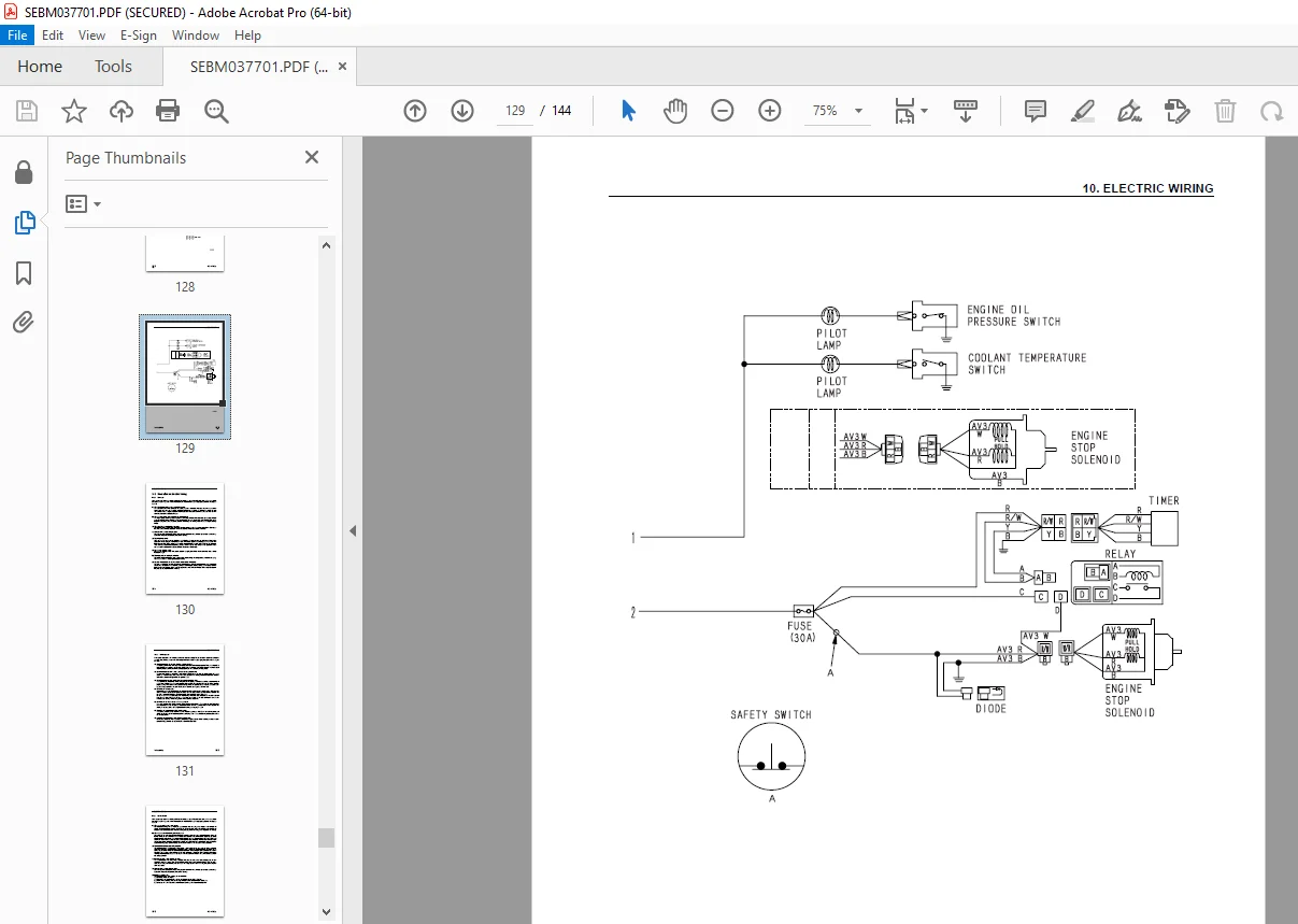
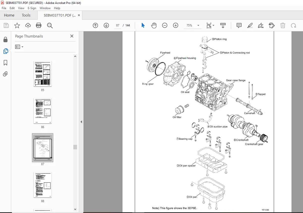
Komatsu 70E-5,76E-5 Series Diesel Engine Shop Manual SEBM037701 PDF
$27.95
Komatsu 70E-5,76E-5 Series Diesel Engine Shop Manual SEBM037701 – PDF DOWNLOAD
Description
Komatsu 70E-5,76E-5 Series Diesel Engine Shop Manual SEBM037701 – PDF DOWNLOAD
FILE DETAILS:
Komatsu 70E-5,76E-5 Series Diesel Engine Shop Manual SEBM037701 – PDF DOWNLOAD
Language : English
Pages : 144
Downloadable : Yes
File Type : PDF
IMAGES PREVIEW OF THE MANUAL:
TABLE OF CONTENTS:
Komatsu 70E-5,76E-5 Series Diesel Engine Shop Manual SEBM037701 – PDF DOWNLOAD
COVER . 1
CONTENTS 15
1. GENERAL 16
1.1 SPECIFICATIONS 17
1.2 ENGINE EXTERNAL VIEWS . 19
1.3 STRUCTURAL DESCRIPTION 20
2. INSPECTION AND ADJUSTMENT 21
2.1 PERIODIC MAINTENANCE SCHEDULE . 22
2.2 PERIODIC INSPECTION AND MAINTENANCE PROCEDURE . 23
2.2.1 CHECK BEFORE DAILY OPERATION . 23
2.2.2 INSPECTION AFTER INITIAL 50 HOURS OPERATION 25
2.2.3 INSPECTION EVERY 50 HOURS . 28
2.2.4 INSPECTION EVERY 250 HOURS OR 3 MONTHS 32
2.2.5 INSPECTION EVERY 500 HOURS OR 6 MONTHS 35
2.2.6 INSPECTION EVERY 1,000 HOURS OR ONE YEAR 37
2.2.7 INSPECTION EVERY 2000 HOURS OR 2 YEARS 43
2.3 ADJUSTING THE NO-LOAD MAXIMUM OR MINIMUM SPEED 45
2.4 SENSOR INSPECTION . 46
2.4.1 OIL PRESSURE SWITCH . 46
2.4.2 THERMO SWITCH . 46
2.5 WATER LEAK CHECK IN COOLING WATER SYSTEM 46
2.6 RADIATOR CAP INSPECTION . 47
2.7 THERMOSTAT INSPECTION 47
2.8 ADJUSTING OPERATION 48
2.9 LONG STORAGE 48
3. TROUBLESHOOTING 49
3.1 PREPARATION BEFORE TROUBLESHOOTING 50
3.2 QUICK REFERENCE TABLE FOR TROUBLESHOOTING . 51
3.3 TROUBLESHOOTING BY MEASURING COMPRESSION PRESSURE . 54
4. DISASSEMBLY, INSPECTION AND REASSEMBLY OF ENGINES 56
4.1 COMPLETE DISASSEMBLY AND REASSEMBLY . 57
4.1.1 INTRODUCTION 57
4.1.2 SPECIAL SERVICE TOOLS . 58
4.1.3 COMPLETE DISASSEMBLY 63
4.1.4 PRECAUTIONS BEFORE AND DURING REASSEMBLY 67
4.1.5 ADJUSTING OPERATION 67
4.2 CYLINDER HEAD: DISASSEMBLY, INSPECTION AND REASSEMBLY . 68
4.2.1 COMPONENTS (2-VALVE CYLINDER HEAD) 68
4.2.2 DISASSEMBLY PROCEDURE . 69
4.2.3 REASSEMBLY PROCEDURE 69
4.2.4 SERVICING POINTS 70
4.2.5 PARTS INSPECTION AND MEASUREMENT 74
4.2.6 VALVE SEAT CORRECTION 78
4.2.7 VALVE GUIDE REPLACEMENT 79
4.2.8 VALVE STEM SEAL REPLACEMENT . 80
4.3 GEAR TRAIN AND CAMSHAFT . 81
4.3.1 COMPONENTS 81
4.3.2 DISASSEMBLY PROCEDURE . 81
4.3.3 REASSEMBLY PROCEDURE 82
4.3.4 SERVICING POINTS 82
4.3.5 PARTS INSPECTION AND MEASUREMENT . 85
4.3.6 OIL SEAL REPLACEMENT (GEAR CASE SIDE) . 86
4.3.7 CAMSHAFT BUSHING REPLACEMENT . 86
4.4 CYLINDER BLOCK 87
4.4.1 COMPONENTS 87
4.4.2 DISASSEMBLY PROCEDURE . 88
4.4.3 REASSEMBLY PROCEDURE 88
4.4.4 SERVICING POINTS 88
4.4.5 PARTS INSPECTION AND MEASUREMENT 92
4.4.6 CYLINDER BORE CORRECTION 101
4.4.7 PISTON PIN METAL REPLACEMENT .102
4.4.8 OIL SEAL REPLACEMENT (FLYWHEEL HOUSING SIDE) 102
5. LUBRICATION SYSTEM 103
5.1 LUBRICATION SYSTEM DIAGRAM 104
5.2 TROCHOID PUMP COMPONENTS 105
5.3 DISASSEMBLY (REVERSE THE PROCEDURE BELOW FOR ASSEMBLY) 105
5.4 SERVICING POINTS 105
5.5 PARTS INSPECTION AND MEASUREMENT .106
6. COOLING SYSTEM 107
6.1 COOLING WATER SYSTEM .108
6.2 COOLING WATER PUMP COMPONENTS .108
6.3 DISASSEMBLY (REVERSE THE PROCEDURE BELOW FOR ASSEMBLY) 109
6.4 SERVICING POINTS 109
7. FUEL INJECTION PUMP/GOVERNOR .110
7.1 INTRODUCTION .111
7.2 FUEL INJECTION PUMP .111
7.2.1 FUEL SYSTEM DIAGRAM .111
7.2.2 EXTERNAL VIEW AND COMPONENTS 112
7.2.3 DISASSEMBLY PROCEDURE .113
7.2.4 ASSEMBLY PROCEDURE 113
7.2.5 CONFIRMATION AND ADJUSTMENT OF FUEL INJECTION TIMING 113
7.2.6 CONFIRMATION AND ADJUSTMENT OF NO-LOAD MAXIMUM AND MINIMUM SPEED 113
8. THE SPECIFICATIONS OF A STARTING MOTOR AND THE CHARACTERISTICS .114
8.1 THE SPECIFICATIONS AND THE CHARACTERISTICS 115
8.1.1 SPECIFICATIONS 115
8.1.2 CHARACTERISTICS .115
8.2 THE STRUCTURE OF A STARTING MOTOR AND THE WIRING DIAGRAM 116
8.2.1 STRUCTURE .116
8.2.2 WIRING DIAGRAM OF A STARTING MOTOR 117
8.3 PERFORMANCE .117
9. ALTERNATOR .118
9.1 20A ALTERNATOR 119
9.1.1 SPECIFICATIONS 119
9.1.2 STRUCTURE .120
9.1.3 WIRING DIAGRAM 121
9.1.4 STANDARD OUTPUT CHARACTERISTICS .121
9.1.5 INSPECTION 122
9.2 40A ALTERNATOR .123
9.2.1 COMPONENTS 123
9.2.2 SPECIFICATIONS 124
9.2.3 WIRING DIAGRAM 124
9.2.4 STANDARD OUTPUT CHARACTERISTICS 125
9.2.5 INSPECTION 125
9.2.6 TROUBLESHOOTING 126
10.ELECTRIC WIRING .127
10.1 ELECTRIC WIRING DIAGRAM 128
10.2 PRECAUTION ON ELECTRIC WIRING 130
10.2.1 ALTERNATOR .130
10.2.2 STARTING MOTOR .131
10.2.3 CURRENT LIMITER 132
10.2.4 SECTION AREA AND RESISTANCE OF ELECTRIC WIRE .133
11.SERVICE STANDARDS 134
11.1 ENGINE TUNING 135
11.2 ENGINE BODY 136
11.2.1 CYLINDER HEAD 136
11.2.2 GEAR TRAIN AND CAMSHAFT 137
11.2.3 CYLINDER BLOCK 138
11.3 LUBRICATING OIL SYSTEM (TROCHOID PUMP) .141
12.TIGHTENING TORQUE FOR BOLTS AND NUTS .142
12.1 TIGHTENING TORQUES FOR MAIN BOLTS AND NUTS .143
12.2 TIGHTENING TORQUES FOR STANDARD BOLTS AND NUTS .144
DESCRIPTION:
Komatsu 70E-5,76E-5 Series Diesel Engine Shop Manual SEBM037701 – PDF DOWNLOAD
PREFACE:
This manual describes the service procedures for the 70E, 76E-5 series engines.
Please use this manual for accurate, quick and safe servicing of the said engine. Since the explanation in this
manual assumes the standard type engine, the specifications and components may partially be different from
the engine installed on individual machine. Please also refer to the shop manual for each machine for details.
PRECAUTIONS FOR SERVICE WORK:
1. Precautions for Safety
Read the safety precautions given at the beginning of this manual carefully and always mind safety in work.
2. Preparation for Service Work
Preparation is necessary for accurate, efficient service work. Check the customer ledger file for the history
of the engine.
• Preceding service date
• Period/operation hours after preceding service
• Problems and actions in preceding service
• Replacement parts expected to be required for service
• Recording form/check sheet required for service
3. Preparation before Disassembly
• Prepare general tools, special service tools, measuring instruments, oil, grease, non reusable parts, and
parts expected to be required for replacement.
• When disassembling complicated portions, put match marks and other marks at places not adversely
affecting the function for easy reassembly.
4. Precautions in Disassembly
• Each time a parts is removed, check the part installed state, deformation, damage, roughening, surface
defect, etc.
• Arrange the removed parts orderly with clear distinction between those to be replaced and those to be
used again.
• Parts to be used again shall be washed and cleaned sufficiently.
• Select especially clean locations and use clean tools for disassembly of hydraulic units such as the fuel
injection pump.
5. Precautions for Inspection and Measurement
Inspect and measure parts to be used again as required to determine whether they are reusable or not.
6. Precautions for Reassembly
• Reassemble correct parts in correct order according to the specified standards (tightening torques, and
adjustment standards). Apply oil important bolts and nuts before tightening when specified.
• Always use genuine parts for replacement.
• Always use new oil seals, O-rings, packings and cotter pins.
• Apply sealant to packings depending on the place where they are used. Apply of grease to sliding contact
portions, and apply grease to oil seal lips.
7. Precautions for Adjustment and Check
Use measuring instruments for adjustment to the specified service standards.
G.B 25/12/24



