
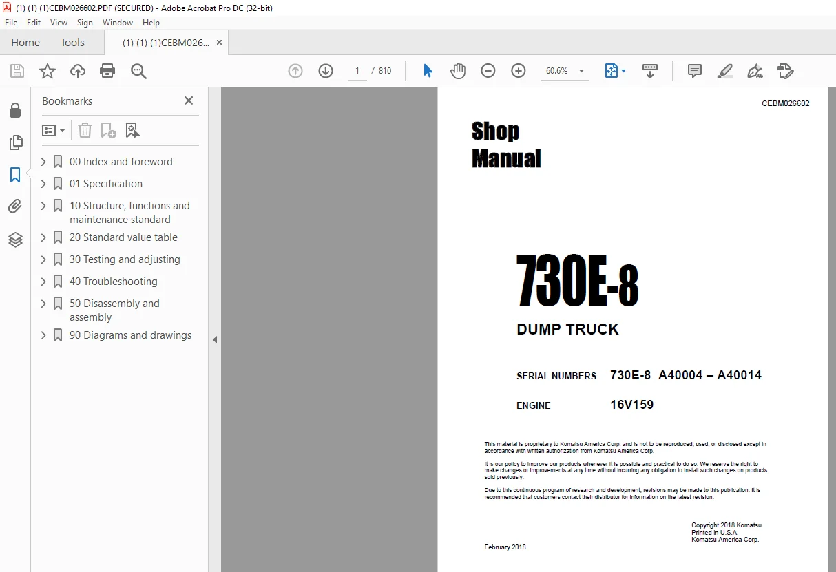
Komatsu 730E-8 DUMP TRUCK Shop Manual CEBM026602 – PDF DOWNLOAD
$33.95
Komatsu 730E-8 DUMP TRUCK Shop Manual CEBM026602 – PDF DOWNLOAD
SERIAL NUMBERS 730E-8 A40004 – A40014
ENGINE 16V159
Description
Komatsu 730E-8 DUMP TRUCK Shop Manual CEBM026602 – PDF DOWNLOAD
FILE DETAILS:
Komatsu 730E-8 DUMP TRUCK Shop Manual CEBM026602 – PDF DOWNLOAD
Language : English
Pages :810
Downloadable : Yes
File Type : PDF
DESCRIPTION:
Komatsu 730E-8 DUMP TRUCK Shop Manual CEBM026602 – PDF DOWNLOAD
SERIAL NUMBERS 730E-8 A40004 – A40014
ENGINE 16V159
Foreword
- This manual is written for use by the operator and/or the service technician. It is designed to help these persons to become fully knowledgeable of the truck and all of its systems in order to keep it operating safely and efficiently. All operators and maintenance personnel should read and understand the information in this manual before operating the truck or performing maintenance and/or operational checks on the truck.
- All safety notices, warnings, and cautions should be understood and followed when operating the truck or performing repairs on the truck. The first section covers component descriptions, truck specifications and safe work practices, as well as other general information. The major portion of the manual pertains to disassembly, service and reassembly.
- Each major serviceable area is dealt with individually. For example, the disassembly, service and reassembly of the radiator group is discussed as a unit. The same is true of the engine and engine accessories, and so on through the entire mechanical detail of the truck.
- Disassembly should be carried only as far as necessary to accomplish needed repairs. The illustrations used in this manual are typical of the component shown and may not be an exact reproduction of what is found on the truck. This manual shows dimensioning of U.S. standard and metric (SI) units throughout. All references to “right,” “left,” “front,” or “rear” are made with respect to the operator’s normal seated position unless specifically stated otherwise.
- When assembly instructions are provided without references to specific torque values, standard torque values should be used. Standard torque values are shown in torque charts later in this section. Specific torques, when provided in the text, are in bold face type, such as 135 N·m (100 ft lb). All torque specifications have ±10% tolerance unless otherwise specified. A product identification plate is located on the frame in front of the right side front wheel. It designates the Truck Model Number, Product Identification Number (vehicle serial number), and Maximum GVW (Gross Vehicle Weight) rating. The KOMATSU truck model designation consists of three numbers and one letter (i.e. 960E).
- The three numbers represent the basic truck model. The letter “E” designates an Electrical wheel motor drive system. The Product Identification Number (vehicle serial number) contains information which identifies several characteristics of this unit. For a more detailed explanation, refer to the Operation and Maintenance Manual. The Gross Vehicle Weight (GVW) is what determines the load on the drive train, frame, tires, and other components.
- The vehicle design and application guidelines are sensitive to the maximum GVW. GVW is total weight: empty vehicle weight + fuel & lubricants + payload. To determine the allowable payload, fill all lubricants to the proper level and fill the fuel tank of an empty truck (which includes all accessories, body liners, tailgates, etc.), and then weigh the truck. Record this value and subtract it from the GVW. The result is the allowable payload.
TABLE OF CONTENTS:
Komatsu 730E-8 DUMP TRUCK Shop Manual CEBM026602 – PDF DOWNLOAD
SERIAL D31S-1s 25001 NUMBERS D31Q-1s 2soo1
00 Index and foreword
Index CEN00022-02
Composition of shop manual 2
Table of contents 4
Foreword, safety and general information CEN00002-09
Foreword 4
How to read the shop manual 5
General safety 7
Precautions before operating the truck 10
Precautions while operating the truck 12
Working near batteries 15
Precautions before performing service17
Precautions while performing service20
Tires 22
Precautions for performing repairs 25
Precautions for welding on the truck 26
Capacitor discharge system 27
Handling electrical equipment and hydraulic components 35
Standard tightening torques 43
Conversion tables48
01 Specification
Specification and technical data CEN01009-02
Specification drawing3
Specifications 4
Weight table 6
Fuel, coolant and lubricants 7
10 Structure, function and maintenance standard
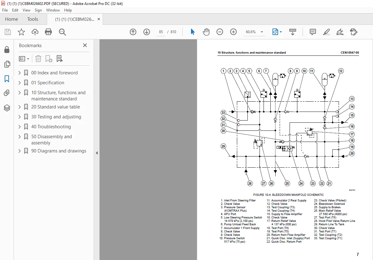
Steering circuit CEN10047-00
Steering circuit operation3
Steering circuit components 4
Steering/brake pump operation 16
Hoist circuit CEN10048-01
Hoist circuit operation3
Hoist circuit components 4
Hoist pilot valve operation 7
Brake circuits CEN10049-00
General information3
Service brake circuit operation 3
Secondary braking and auto apply5
Parking brake circuit operation5
Wheel brake lock circuit operation 6
Brake warning circuit operation 6
00 Index and foreword CEN00022-02
5
Suspensions CEN10050-00
General information3
Front suspension wear data3
Rear suspension wear data 4
Electrical system, 24V CEN10051-00
Battery supply system3
Isolation box 4
Auxiliary control cabinet components5
Relay boards 6
Electric cranking motor system (with prelube) 8
Body-up switch9
Hoist limit switch10
Interface module (IM) CEN10052-00
General information2
Sensors 2
Interface module inputs and outputs 3
Electrical system, AC drive CEN10053-00
General system operation 2
AC drive system components 4
DSC software functions6
Alternator field control 10
Event detection and processing 12
Event restrictions13
Event logging and storage 13
Abnormal conditions/overriding functions 14
Electronic accelerator and retard pedals15
Drive system component abbreviations & locations16
Cab air conditioning CEN10008-02
General information2
Principles of refrigeration 3
Air conditioning system components5
Air conditioning system electrical circuit9
20 Standard value table
Standard value table CEN20004-00
Standard value table for truck 3
30 Testing and adjusting
Steering and hoist hydraulic system CEN30054-00
General information on system checkout2
Steering system checkout procedures 2
Steering and brake pump pressure control adjustments3
Shock & suction valve settings5
Leakage tests6
Accumulator bleed down procedure7
Low steering pressure switch7
CEN00022-02 00 Index and foreword
6
Toe-in adjustment 12
Steering system checkout data sheet14
Checking hoist system pressures15
Hoist counterbalance valve 17
Hoist cylinder leakage test 18
Hoist system checkout data sheet21
Hydraulic system flushing22
Oil cleanliness check27
Hydraulic system flushing checkout data sheet 28
Brake system CEN30056-00
General information on system checkout 2
Brake circuit checkout procedure2
Brake system checkout data sheet 11
Service brake conditioning (burnishing) procedure 17
Parking brake adjustment procedure 20
Brake bleeding procedure 20
Piston assembly return spring force and built-in clearance (BIC) 21
Valve bench test and adjustment 26
Accumulators and suspension CEN30057-00
Accumulator charging and storage2
Bladder accumulator charging procedure 3
Bladder accumulator leak testing 7
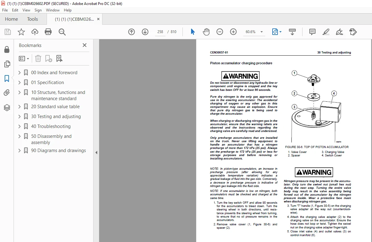
Piston accumulator charging procedure8
Piston accumulator storage10
Piston accumulator leak testing10
Suspension oiling and charging procedure 11
Suspension pressure test18
KOMTRAX Plus CEN30095-00
General information2
Using the KOMTRAX Plus system 5
KOMTRAX Plus data items7
KOMTRAX Plus diagnostic features 14
KOMTRAX Plus controller15
KOMTRAX Plus software 17
KOMTRAX Plus system setup 18
KOMTRAX Plus initialization procedure19
KOMTRAX Plus controller checkout 30
Orbcomm controller34
Interface module (IM) CEN30051-00
Interface module software 3
Interface module checkout procedures 5
Cab air conditioning CEN30029-00
General information2
Service tools and equipment 3
Detecting leaks6
System performance test 7
00 Index and foreword CEN00022-02
7
Checking system oil 8
System flushing9
Installing the manifold gauge set10
Recovering and recycling refrigerant 11
Evacuating the air conditioning system13
Charging the air conditioning system 14
40 Troubleshooting
Fuse and circuit breaker locations CEN40113-00
Fuse and circuit breaker locations 3
AC drive system fault codes CEN40114-01
DID panel fault code tables 3
Troubleshooting by fault code, Part 1 CEN40108-00
Fault Code A001: Left front suspension pressure sensor signal high3
Fault Code A002: Left front suspension pressure sensor signal low 4
Fault Code A003: Right front suspension pressure sensor signal high 5
Fault Code A004: Right front suspension pressure sensor signal low6
Fault Code A005: Left rear suspension pressure sensor signal high7
Fault Code A006: Left rear suspension pressure sensor signal low8
Fault Code A007: Right rear suspension pressure sensor signal high 9
Fault Code A008: Right rear suspension pressure sensor signal low10
Fault Code A009: Incline sensor signal high 11
Fault Code A010: Incline sensor signal low 12
Fault Code A011: Payload meter speed sensor signal has failed 13
Fault Code A013: Body up switch has failed14
Fault Code A014: Payload meter checksum computation has failed 15
Fault Code A016: Payload meter write to flash memory has failed 16
Fault Code A017: Payload meter flash memory read has failed17
Fault Code A018: Right rear flat suspension cylinder warning 18
Fault Code A019: Left rear flat suspension cylinder warning20
Fault Code A022: Carryback load excessive 22
Fault Code A101: High pressure detected across an hydraulic pump filter 24
Fault Code A103: Hydraulic Oil Temp – Tank Sensor Low 25
Fault Code A104: Hydraulic oil temp – Tank sensor high 26
Fault Code A105: Fuel level sensor shorted to ground indicating a false high fuel level 27
Fault Code A109: GE has generated a propel system reduced level signal29
Fault Code A111 & A247: Low steering pressure warnings 30
Fault Code A115: Low steering precharge pressure detected 32
Fault Code A117 & A261: Low brake accumulator pressure warnings 33
Fault Code A118: Brake pressure is low while in brake lock34
Fault Code A123: GE has generated a reduced retarding caution 35
Fault Code A124: GE has generated a no propel / no retard warning 36
Fault Code A125: GE has generated a no propel warning 37
Fault Code A126: Oil level in the hydraulic tank is low 38
Fault Code A127: IM-furnished +5 volt output for sensors is low39
Fault Code A128: IM-furnished +5 volt output for sensors is high 40
CEN00022-02 00 Index and foreword
8
Fault Code A139 & A310: Low fuel warnings41
Troubleshooting by fault code, Part 2 CEN40109-00
Fault Code A152: Starter failure 3
Fault Code A153: Battery voltage is low with the truck in operation 4
Fault Code A154: Battery charging voltage is excessive 6
Fault Code A155: Battery charging voltage is low7
Fault Code A158: The fuel level sensor is open or shorted high indicating a false
low fuel level8
Fault Code A184: J1939 data link is not connected 9
Fault Code A190: Auto lube control has detected an incomplete lube cycle 10
Fault Code A193: Hydraulic tank oil temperature is high 12
Fault Code A198: Hoist pressure 1 sensor is high 13
Fault Code A200: Steering pressure sensor is high 14
Fault Code A201: Brake pressure sensor is high15
Fault Code A202: Hoist pressure 1 sensor is low 16
Fault Code A204: Steering pressure sensor is low 17
Fault Code A205: Brake pressure sensor is low 18
Fault Code A206: Ambient temperature sensor is high19
Fault Code A207: Ambient temperature sensor is low 20
Fault Code A213: Parking brake should have applied but is detected as
not having applied 21
Fault Code A214: Parking brake should have released but is detected as
not having released 23
Fault Code A216: An open or short to ground has been detected in the parking brake
command valve circuit25
Fault Code A223: Excessive engine cranking has occurred or a jump start has
been attempted 27
Fault Code A230: Parking brake has been requested while truck still moving29
Fault Code A231: The body is up while traveling or intending to travel 31
Fault Code A233: Drive system CAN/RPC Control Link not connected33
Fault Code A235: Steering accumulator is in the process of being bled down 35
Fault Code A236: The steering accumulator has not properly bled after 90 seconds37
Fault Code A237: The CAN/RPC connection to the display is open38
Fault Code A240: The key switch input to the interface module is open39
Troubleshooting by fault code, Part 3 CEN40110-00
Fault Code A242: Fuel gauge within the display panel is defective 4
Fault Code A243: Engine coolant temperature gauge within the display panel is defective 5
Fault Code A244: Drive system temperature gauge within the display panel is defective 6
Fault Code A245: Hydraulic oil temperature gauge within the display panel is defective 7
Fault Code A246: Payload meter reports truck overload 8
Fault Code A248: Status module within the display panel is defective 9
Fault Code A249: Red warning lamp within the display (driven by IM) is shorted 10
Fault Code A250: Battery voltage is low with the truck parked 11
Fault Code A251: Sonalert used with the display (driven by IM) is open or
shorted to ground 13
Fault Code A252: Start enable output circuit is either open or shorted to ground14
Fault Code A253: Steering bleed circuit is not open while running 15
00 Index and foreword CEN00022-02
9
Fault Code A255: IM has detected a fault on IM output 1N This fault is disabled and
not wired16
Fault Code A256: Red warning lamp in the display (driven by IM) is open17
Fault Code A257: Payload CAN/RPC is not connected18
Fault Code A258: Steering accumulator bleed pressure switch circuit is defective 19
Fault Code A260: Parking brake failure 20
Fault Code A262: Steering bleed valve circuit open during shutdown 22
Fault Code A264: Parking brake relay circuit is defective24
Fault Code A265: Service brake failure 25
Fault Code A266: Selector lever was not in park while attempting to crank engine 27
Fault Code A267: Parking brake was not set while attempting to crank engine 28
Fault Code A268: Secondary engine shutdown while cranking 29
Fault Code A270: Brake lock switch power supply is not on when required30
Fault Code A271: Shifter not in gear32
Fault Code A272: Brake lock switch power supply is not off when required33
Fault Code A273: A fault has been detected in the hoist or steering pump filter
pressure switch circuit35
Fault Code A274: A brake setting fault has been detected36
Fault Code A275: A starter has been detected as engaged without a cranking attempt 38
Troubleshooting by fault code, Part 4 CEN40111-00
Fault Code A277: Parking brake applied while loading3
Fault Code A278: Service brake applied while loading4
Fault Code A279: Low steering pressure switch is defective5
Fault Code A280: Steering accumulator bleed down switch is defective 6
Fault Code A281: Brake lock degrade switch is defective 7
Fault Code A282: The number of excessive cranking counts and jump starts without
the engine running has reached 78
Fault Code A283: An engine shutdown delay was aborted because the parking brake
was not set 10
Fault Code A284: An engine shutdown delay was aborted because the secondary
shutdown switch was operated 12
Fault Code A285: The parking brake was not set when the key switch was turned off 13
Fault Code A286: A fault was detected in the shutdown delay relay circuit14
Fault Code A292: The shutdown delay relay has remained on after the latched
keyswitch circuit is off15
Fault Code A303: Shifter is defective16
Fault Code A304: Auto lube grease level fault17
Fault Code A305: Auto lube circuit is defective18
Fault Code A307: Both GE Inverters disabled 19
Fault Code A309: No brakes applied when expected 20
Fault Code A311: Brake lock switch on when it shouldn’t be 22
Fault Code A312: The DCDC Converter 12 volt circuit sensing is producing low readings23
Fault Code A313: The DCDC converter 12 volt circuit sensing is producing high readings 24
Fault Code A315: The DCDC converter 12 volt circuit is low25
Fault Code A316: Starter engagement has been attempted with engine running26
Fault Code A318: Unexpected power loss to Interface Module 28
Fault Code A328: Drive system not powered up29
CEN00022-02 00 Index and foreword
10
Fault Code A333: The hydraulic ladder controller has declared a ladder fault30
Troubleshooting by fault code, Part 5 CEN40112-00
Fault Code A350: Overload on output 1B 3
Fault Code A351: Overload on output 1E 4
Fault Code A352: Overload on output 1H 5
Fault Code A353: Overload on output 1J 6
Fault Code A354: Overload on output 1K 7
Fault Code A355: Overload on output 1L8
Fault Code A356: Overload on output 1M9
Fault Code A357: Overload on output 1N 10
Fault Code A358: Overload on output 1P 11
Fault Code A359: Overload on output 1R 12
Fault Code A360: Overload on output 1S 13
Fault Code A361: Overload on output 1T14
Fault Code A362: Overload on output 1U 15
Fault Code A363: Overload on output 1X 16
Fault Code A364: Overload on output 1Y 17
Fault Code A365: Overload on output 1Z18
Cab air conditioning CEN40008-01
Preliminary checks 3
Diagnosis of gauge readings and system performance 3
Troubleshooting by manifold gauge set readings4
50 Disassembly and assembly
Service tools CEN50036-00
Special tool group3
Additional service tools3
Locally made tools4
Wheels, spindles and rear axle CEN50037-00
General precautions for tires and rims 3
Rim components 4
Wheel stud maintenance5
Removal and installation of front wheel6
Removal and installation of rear wheel 8
Rim and tire service11
Removal and installation of front wheel hub and spindle 18
Disassembly and assembly of front wheel hub and spindle26
Hub floating ring seal assembly and installation 39
Removal and installation of rear axle 44
Removal and installation of anti-sway bar47
Removal and installation of pivot pin50
Pivot eye and bearing service 52
Removal and installation of wheel motor54
00 Index and foreword CEN00022-02
11
Brake system CEN50038-00
Removal and installation of brake valve3
Disassembly and assembly of brake valve/pedal assembly 6
Removal and installation of brake manifold 8
Disassembly and assembly of brake manifold 10
Disassembly and assembly of brake accumulator 11
Removal and installation of front brake caliper 15
Disassembly and assembly of front brake caliper16
Removal and installation of rear brake caliper 19
Disassembly and assembly of rear brake caliper25
Steering system CEN50039-00
Removal and installation of steering control unit3
Disassembly and assembly of steering control unit 5
Removal and installation of steering column10
Removal and installation of steering wheel13
Removal and installation of bleeddown manifold 14
Removal and installation of flow amplifier 17
Removal and installation of steering cylinders and tie rod 19
Disassembly and assembly of steering cylinders22
Removal and installation of steering/brake pump 25
Removal and installation of piston steering accumulator 29
Disassembly and assembly of piston steering accumulators32
Suspensions CEN50040-00
Removal and installation of front suspension3
Disassembly and assembly of front suspension 11
Removal and installation of rear suspension 16
Disassembly and assembly of rear suspension 20
Operator cab CEN50042-00
Removal and installation of operator cab3
Removal and installation of cab door 7
Disassembly and assembly of cab door8
Adjustment of cab door 15
Removal and installation of side window glass 17
Removal and installation of windshield and rear window glass 19
Removal and installation of windshield wiper motor 20
Removal and installation of windshield wiper arm 21
Removal and installation of windshield wiper linkage 22
Removal and installation of operator seat23
Replacing the seat compressor (standard seat) 24
Removal and installation of seat belts (standard seat)30
Removal and installation of seat belts (optional seat) 32
Cab air conditioning CEN50028-02
Replacement of air conditioning system components3
CEN00022-02 00 Index and foreword
12
90 Diagrams and drawings
Hydraulic circuit diagrams CEN90011-01
Steering and hoist hydraulic circuit diagramXB6903-00
Brake hydraulic circuit diagram XS7600-01
Auxiliary hydraulic circuit diagram XS8100-01
Electrical circuit diagrams CEN90012-01
Electrical circuit diagram 58D-06-00440-02
Connectors table and arrangementHE491
IMAGES PREVIEW OF THE MANUAL:
S.M 12/12/24



