Komatsu 730E Dump Truck Operation & Maintenance Manual A30181 A30211 – PDF DOWNLOAD
Original price was: $51.95.$16.95Current price is: $16.95.
Komatsu 730E Dump Truck Operation & Maintenance Manual
SERIAL NUMBER A30181 – A30211
Book Code: CEAM006700
Description
Komatsu 730E Dump Truck Operation & Maintenance Manual
FILE DETAILS:
Komatsu 730E Dump Truck Operation & Maintenance Manual
Language : English
Pages : 160
Downloadable : Yes
File Type : PDF
Size: 2.47 MB
Book Code: CEAM006700
KOMATSU 730E DUMP TRUCK OPERATION & MAINTENANCE MANUAL A30181 A30211 – PDF DOWNLOAD:
DESCRIPTION:
Komatsu 730E Dump Truck Operation & Maintenance Manual
FOREWORD:
This manual is written for use by the operator and/or the service technician. It is designed to help these persons to become fully knowledgeable of the truck and all of its systems in order to keep it operating safely and efficiently. All operators and maintenance personnel should read and understand the information in this manual before operating the truck or performing maintenance and/or operational checks on the truck. All safety notices, warnings, and cautions should be understood and followed when operating the truck or performing repairs on the truck.
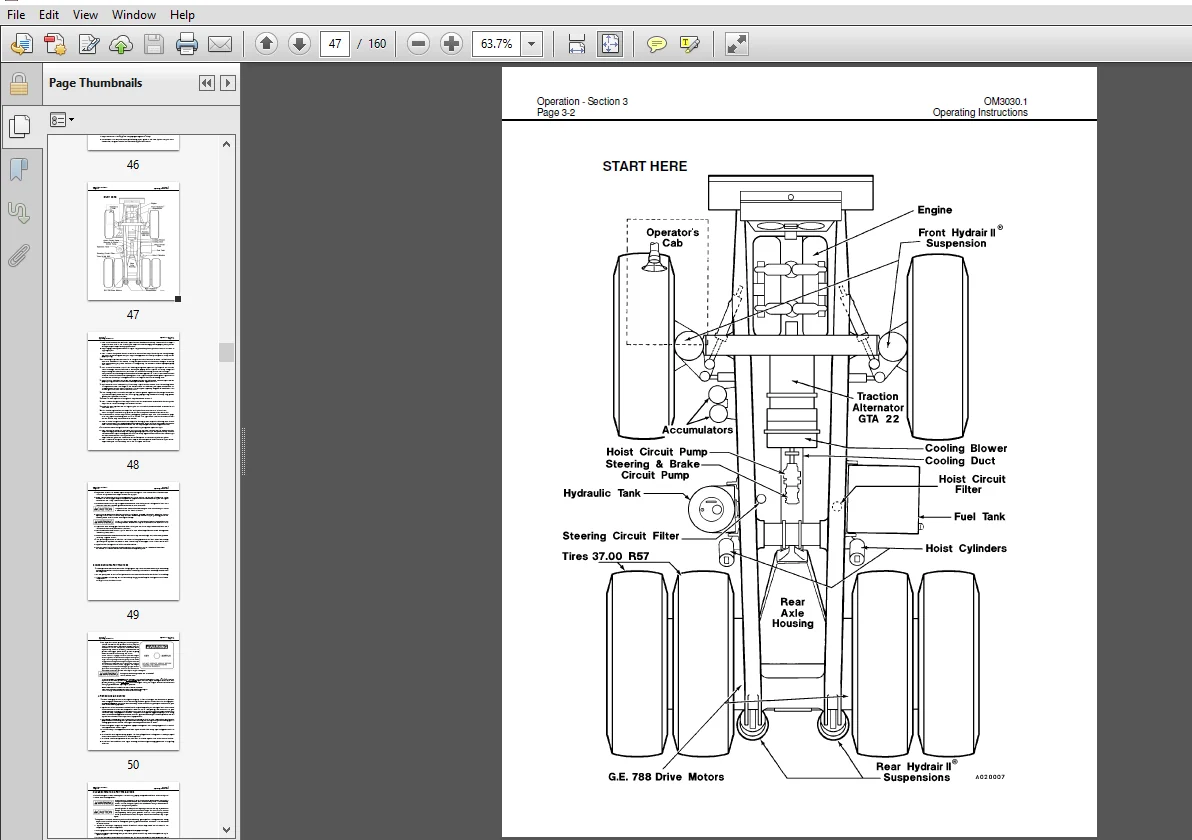
- The first section covers component descriptions, truck specifications and safe work practices, as well as other general information. The major portion of the manual pertains to disassembly, service and reassembly. Each major serviceable area is dealt with individually. For example, the disassembly, service and reassembly of the radiator group is discussed as a unit. The same is true of the engine and engine accessories, and so on through the entire mechanical detail of the truck.
- Disassembly should be carried only as far as necessary to accomplish needed repairs. The illustrations used in this manual are typical of the component shown and may not be an exact reproduction of what is found on the truck. This manual shows dimensioning of U.S. standard and metric (SI) units throughout.
- All references to “right,” “left,” “front,” or “rear” are made with respect to the operator’s normal seated position unless specifically stated otherwise. When assembly instructions are provided without references to specific torque values, standard torque values should be used.
- Standard torque values are shown in torque charts later in this section. Specific torques, when provided in the text, are in bold face type, such as 135 N·m (100 ft lb). All torque specifications have ±10% tolerance unless otherwise specified.
- A product identification plate is located on the frame in front of the right side front wheel. It designates the Truck Model Number, Product Identification Number (vehicle serial number), and Maximum GVW (Gross Vehicle Weight) rating. The KOMATSU truck model designation consists of three numbers and one letter (i.e. 960E). The three numbers represent the basic truck model. The letter “E” designates an Electrical wheel motor drive system.
- The Product Identification Number (vehicle serial number) contains information which identifies several characteristics of this unit. For a more detailed explanation, refer to the Operation and Maintenance Manual. The Gross Vehicle Weight (GVW) is what determines the load on the drive train, frame, tires, and other components.
- The vehicle design and application guidelines are sensitive to the maximum GVW. GVW is total weight: empty vehicle weight + fuel & lubricants + payload. To determine the allowable payload, fill all lubricants to the proper level and fill the fuel tank of an empty truck (which includes all accessories, body liners, tailgates, etc.), and then weigh the truck. Record this value and subtract it from the GVW. The result is the allowable payload.
TABLE OF CONTENTS:
Komatsu 730E Dump Truck Operation & Maintenance Manual
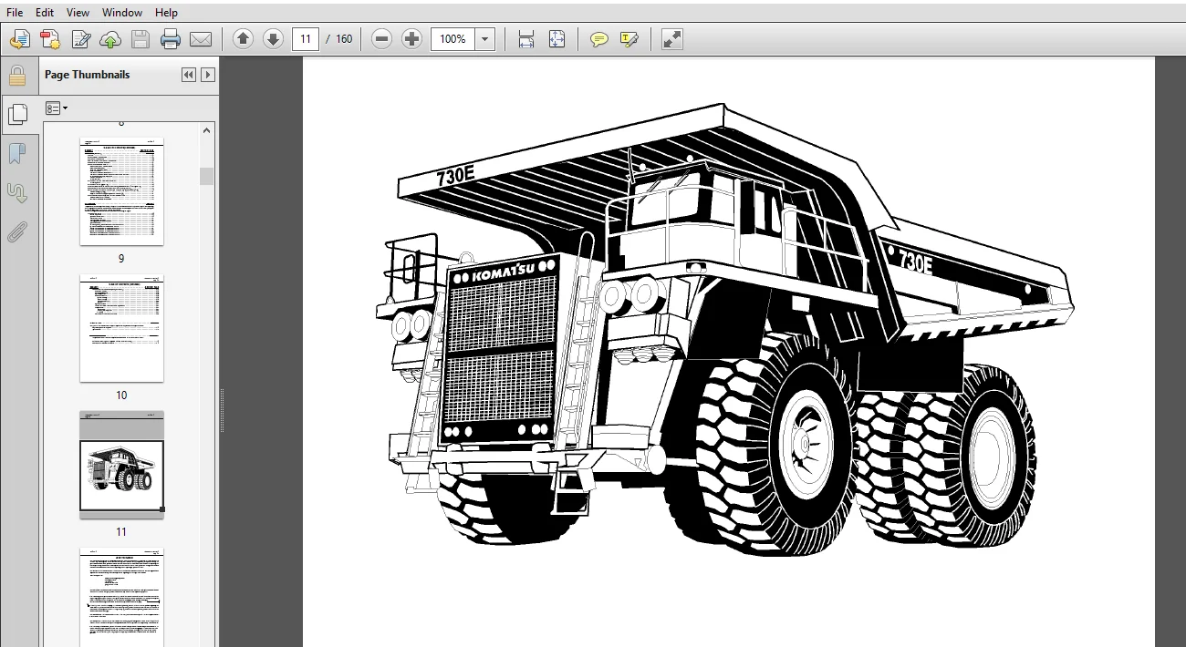
MAIN MENU.....................................................  0
COVER.........................................................  1
INTRODUCTION..................................................  6
	FOREWARD..................................................  6
	ALERTS....................................................  7
	TABLE OF CONTENTS.........................................  8
	TRUCK MODEL ILLUSTRATION.................................. 11
	ABOUT THIS MANUAL......................................... 12
	STANDARD CHARTS AND TABLES................................ 14
SAFETY........................................................ 20
	GENERAL SAFETY RULES...................................... 20
	PRECAUTIONS DURING OPERATION.............................. 24
		Before Starting Engine................................ 24
		Operating Machine..................................... 25
		Battery............................................... 28
		Towing................................................ 29
	PRECAUTIONS FOR MAINTENANCE............................... 30
		Before Carrying Out Maintenance....................... 30
		During Maintenance.................................... 31
		Tires................................................. 34
	ADDITIONAL JOB SITE RULES................................. 35
	WHEN REPAIRS ARE NECESSARY................................ 36
	WARNING, CAUTION, AND INSTRUCTION PLATES / DECALS......... 38
OPERATION..................................................... 46
	OPERATING INSTRUCTIONS.................................... 46
		Preparing For Operation............................... 46
		Safety Is Thinking Ahead.............................. 46
		At The Truck - Ground Level Walk-Around Inspection.... 46
	ENGINE START-UP SAFETY PRACTICES.......................... 49
	AFTER ENGINE HAS STARTED.................................. 50
	MACHINE OPERATION SAFETY PRECAUTIONS...................... 51
	LOADING................................................... 51
	HAULING................................................... 52
	PASSING................................................... 52
	DUMPING................................................... 53
	TOWING.................................................... 55
	SAFE PARKING PROCEDURES................................... 55
	SHUTDOWN PROCEDURE........................................ 56
	DELAYED ENGINE SHUTDOWN PROCEDURE......................... 56
	SUDDEN LOSS OF ENGINE POWER............................... 57
	OPERATOR CAB AND CONTROLS................................. 58
		STEERING WHEEL AND CONTROLS........................... 59
		SERVICE BRAKE PEDAL................................... 60
		DYNAMIC RETARDER PEDAL................................ 60
		THROTTLE PEDAL........................................ 60
		HEATER / AIR CONDITIONER VENTS........................ 60
		HEATER / AIR CONDITIONER COMPARTMENT AND CONTROLS..... 61
		OVER HEAD PANEL AND DISPLAYS.......................... 62
		CENTER CONSOLE........................................ 63
		OPERATOR SEAT......................................... 67
	INSTRUMENT PANEL AND INDICATOR LIGHTS..................... 68
		CONTROL SYMBOLS....................................... 68
	INSTRUMENT PANEL.......................................... 69
	PANEL GAUGES, INDICATORS AND CONTROLS..................... 69
	OVER HEAD STATUS / WARNING INDICATOR LIGHT PANEL.......... 75
	INDICATOR LIGHT SYMBOLS................................... 76
		HAZARD WARNING LIGHTS................................. 82
		LAMP TEST SWITCH / CENTRY DIAGNOSTIC TEST SWITCH...... 82
	CUMMINS ENGINE CENTRY FUEL SYSTEM DIAGNOSTICS............. 83
		DETERMINING FAULT CODES............................... 83
		EXITING THE DIAGNOSTIC MODE........................... 84
MAINTENANCE................................................... 86
	LUBRICATION AND SERVICE................................... 86
		Service Capacities.................................... 86
		Hydraulic Tank Service................................ 86
		Coolant Level Check................................... 87
		Radiator Filling Procedure............................ 87
		Cooling System Recommendations........................ 87
		Lubrication Chart..................................... 88
		10 HOUR (SHIFT) Lubrication and Maintenance Checks.... 89
		50 HOUR Lubrication and Maintenance Checks............ 91
		100 HOUR Lubrication and Maintenance Checks .......... 92
		250 HOUR Lubrication and Maintenance Checks........... 93
		500 HOUR Lubrication and Maintenance Checks........... 95
		1000 HOUR Lubrication and Maintenance Checks.......... 96
		5000 HOUR Lubrication and Maintenance Checks.......... 97
	LINCOLN AUTOMATIC SYSTEM (OPTIONAL)....................... 98
		General Description................................... 98
		System Components.....................................100
		System Operation......................................101
		General Instructions..................................104
			System Priming....................................104
			Lubricant Pump....................................104
			Filter and Reservoir..............................105
			Injectors.........................................106
		System Checkout.......................................107
		24 VDC Solid State Timer Checkout & Adjustment........107
		Pump Rebuild..........................................108
			Disassembly.......................................108
			Cleaning and Inspection...........................108
			Assembly..........................................110
		Preventative Maintenance Procedure....................114
SPECIFICATIONS................................................116
	MAJOR COMPONENT DESCRIPTION...............................116
	SPECIFICATIONS............................................118
OPTIONAL EQUIPMENT............................................120
	PAYLOAD METER II..........................................122
		General Information...................................122
		Lights, Switches, and Components......................123
		Tips for Operation....................................124
		External Display Lights...............................124
		Theory of Operation...................................125
			Basic Description.................................125
			Linkage Factor....................................125
			Brake Lock........................................126
			Sources of Error..................................126
			Typical Data From Service Check Mode..............126
			Example Calculation of Payload....................127
			Calculation of the Calibration Load...............127
		Types of Data Stored..................................128
			Cycle Data........................................128
			Engine ON/OFF Data................................129
			Fault Codes and Warning Data......................129
			Engine Operation..................................130
			Total Payload and Total Number of Cycles..........130
			Other Data........................................130
		Operator Functions....................................131
			Using the Operator Load Counter...................131
				Description...................................131
				Viewing the Operator Load Counter.............131
				Clearing the Operator Load Counter............131
			Dimming the Lights on the Display.................131
		Initial Setup of Payload Meter........................132
			Switch Settings...................................132
			Checking the Operator Check Mode..................132
			Checking the Service Check Mode...................133
				Setting "UP:00"...............................133
				Setting "PL:00"...............................133
			Checking the Gt Setting...........................133
			Checking the Inclinometer Settings................133
			Calibrating a Truck...............................134
		Displays at Start-Up..................................135
		Setup and Maintenance.................................136
			Setting the Speed Limit...........................136
			Setting the Option Code...........................136
			Setting the Machine I.D...........................136
			Setting the Operator I.D..........................137
			Setting the Time and Date.........................137
		Download of Payload and Fault Codes...................137
		Display of Fault Codes................................138
		Charts of Error Codes and Other Information...........140
		Service Check Mode....................................141
			Monitoring Input Signals..........................141
			UP Factor - Payload Calculation Gain..............142
			PL Mode - Load Calculation Timing.................142
		Final Gear Ration Selection...........................143
		Battery Replacement Procedure.........................144
			Replacing the Battery.............................144
			After Replacing the Battery.......................145
		Suspension Pressure Sensor............................145
			Removal...........................................145
			Installation......................................146
		Inclinometer..........................................146
			Removal...........................................146
			Installation......................................146
		Scoreboard............................................147
			Description.......................................147
			Making Connections................................147
			Wiring Diagram....................................148
			Normal Operation of the Scoreboard................149
		Payload Meter Back Panel..............................149
			Connections (AMP Pin Identification)..............150
		Payload Circuit Numbers...............................151
		Payload Meter II Reinitalization Procedure............152
	RADIO, AM / FM CASSETTE...................................154
IMAGES PREVIEW OF THE MANUAL:
PLEASE NOTE:
- This is the SAME exact manual used by your dealers to fix your vehicle.
- The same can be yours in the next 2-3 mins as you will be directed to the download page immediately after paying for the manual.
- Any queries / doubts regarding your purchase, please feel free to contact [email protected]


