Trusted Business
Verified & Licensed
Virus Free Files
100% Safe Downloads
Secure Payment
SSL Protected
Instant Delivery
Available Immediately
Sale!


KOMATSU 730E DUMP TRUCK Operation & Maintenance Manual (SN:A30597 – A30602 & A30604 – A30609) KOMATSU 730E – PDF DOWNLOAD
Original price was: $81.95.$25.95Current price is: $25.95.
- KOMATSU 730E DUMP TRUCK Operation & Maintenance Manual
- SERIAL NUMBER:A30597 – A30602 & A30604 – A30609
- PUBLICATION NUMBER:CEAM022201
Instant PDF Download
Available immediately
Save to Your Device
Download & keep forever
Antivirus Scanned
100% virus-free
Trusted Worldwide
175,000+ customers
Description
KOMATSU 730E DUMP TRUCK Operation & Maintenance Manual (SN:A30597 – A30602 & A30604 – A30609) KOMATSU 730E
KOMATSU 730E DUMP TRUCK OPERATION & MAINTENANCE MANUAL (SN:A30597 – A30602 & A30604 – A30609) KOMATSU 730E – PDF DOWNLOAD:
IMAGE PREVIEW:
DESCRIPTION:
KOMATSU 730E DUMP TRUCK Operation & Maintenance Manual (SN:A30597 – A30602 & A30604 – A30609) KOMATSU 730E
- This manual is written for use by the operator and/or the service technician. It is designed to help these persons to become fully knowledgeable of the truck and all its systems in order to keep it operating safely and efficiently. All operators and maintenance personnel must read and understand the materials in this manual before operating the truck or performing maintenance and/or operational checks on the truck. All safety notices, warnings, and cautions must be understood and followed when operating or repairing the truck.
- A product identification plate is located on the frame in front of the right side front wheel and designates the truck model number, product identification number (vehicle serial number), and maximum GVW (Gross Vehicle Weight) rating.
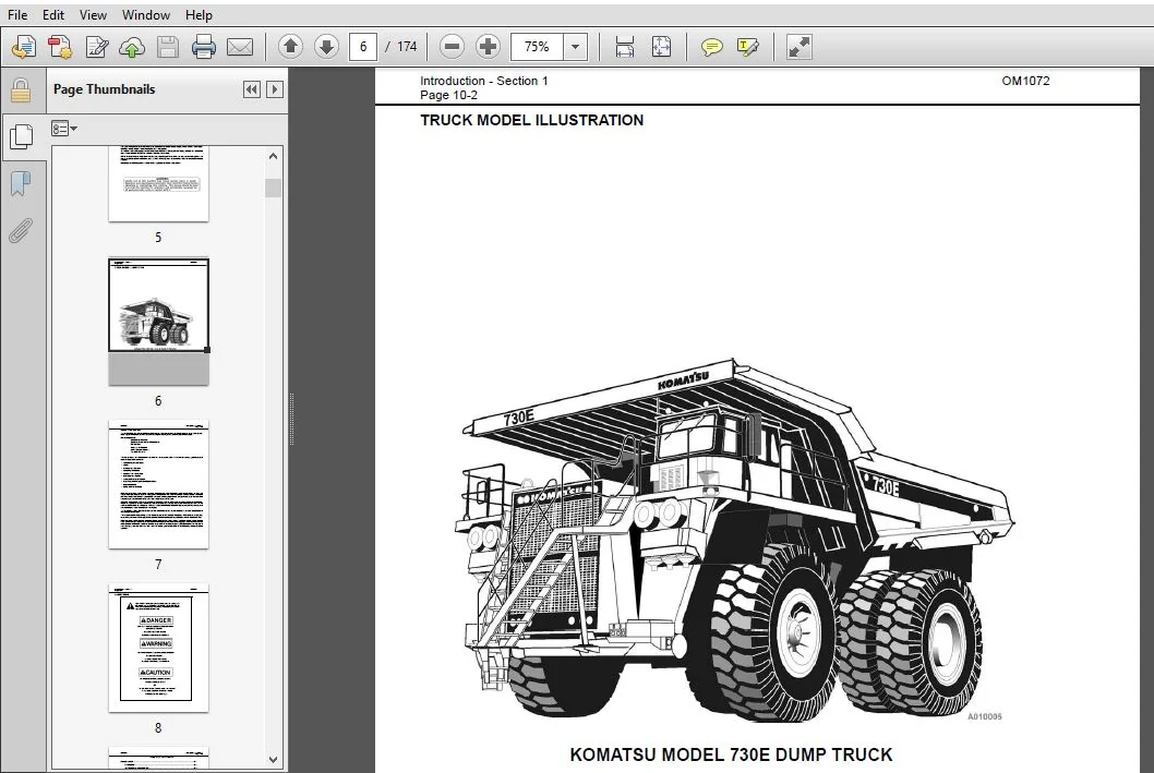
- The Komatsu truck model designation consists of three numbers and one letter (i.e. 930E).
The three numbers represent the basic truck model.
The letter E, when present, designates an electrical wheel motor drive system. - The product identification number (vehicle serial number) contains information which will identify the original manufacturing bill of material for this unit. This complete number will be necessary for proper ordering of many service parts and/or warranty consideration.
- The GVW is what determines the load on the drive train, frame, tires, and other components. The vehicle design and application guidelines are sensitive to the total maximum Gross Vehicle Weight (GVW). GVW is total weight: the empty vehicle weight + the fuel and lubricants + the payload.
TABLE OF CONTENTS:
KOMATSU 730E DUMP TRUCK Operation & Maintenance Manual (SN:A30597 – A30602 & A30604 – A30609) KOMATSU 730E
COVER............................................................................  0
INTRODUCTION.....................................................................  5
	FOREWORD.....................................................................  5
	TRUCK MODEL ILLUSTRATION.....................................................  6
	ABOUT THIS MANUAL............................................................  7
	ALERTS PAGE..................................................................  8
TABLE OF CONTENTS................................................................  9
STANDARD CHARTS AND TABLES....................................................... 19
	EFFECT OF SPECIAL LUBRICANTS On Fasteners and Standard Torque Values......... 19
	STANDARD ASSEMBLY TORQUES For 12-Point, Grade 9 Cap screws (SAE)............. 20
	STANDARD ASSEMBLY TORQUES For Class 10.9 Cap screws & Class 10 Nuts.......... 20
GENERAL SAFETY................................................................... 25
	PERSONAL SAFETY.............................................................. 25
		Safety Rules............................................................. 25
		Truck Safety Features.................................................... 25
		Clothing And Personal Items.............................................. 25
		Unauthorized Modification................................................ 25
		Leaving The Operator’s Seat.............................................. 25
		Mounting And Dismounting................................................. 25
		Fire Extinguishers And First Aid Kits.................................... 26
		Precautions For High Temperature Fluids.................................. 26
		Asbestos Dust Hazard Prevention.......................................... 26
		Fire Prevention For Fuel And Oil......................................... 26
		ROPS Precautions......................................................... 27
		Preventing Injury From Work Equipment.................................... 27
		Precautions For Optional Attachments..................................... 27
		Precautions When Starting The Machine.................................... 27
	PRECAUTIONS FOR TRUCK OPERATION.............................................. 28
		Safety Is Thinking Ahead................................................. 28
		Safety At The Work Site.................................................. 28
		Fire Prevention.......................................................... 28
		Preparing For Operation.................................................. 28
		Ventilation For Enclosed Areas........................................... 28
		Mirrors, Windows, And Lights............................................. 28
		In The Operator’s Cab - Before Starting The Engine....................... 29
		Seat Belts............................................................... 29
	OPERATING THE MACHINE........................................................ 29
		Starting The Engine...................................................... 29
		Truck Operation - General................................................ 29
		Traveling In The Truck................................................... 30
		Precautions When Traveling In Reverse.................................... 30
		Traveling On Slopes...................................................... 30
		Ensuring Good Visibility................................................. 31
		Operating On Snow........................................................ 31
		Avoid Damage To The Dump Body............................................ 31
		Driving Near High-Voltage Cables......................................... 31
		When Loading The Truck................................................... 31
		When Dumping............................................................. 31
		Working On Loose Ground.................................................. 31
		Parking The Machine...................................................... 32
	TOWING....................................................................... 32
	WORKING NEAR BATTERIES....................................................... 32
		Battery Hazard Prevention................................................ 32
		Jump-Starting With Booster Cables........................................ 33
		Jump Starting With Receptacles........................................... 33
	PRECAUTIONS FOR MAINTENANCE.................................................. 34
		BEFORE PERFORMING MAINTENANCE............................................ 34
			Stopping The Engine Before Service................................... 34
			Warning Tag.......................................................... 34
			Proper Tools......................................................... 34
			Securing The Dump Body............................................... 34
		DURING MAINTENANCE....................................................... 35
			Personnel............................................................ 35
			Attachments.......................................................... 35
			Working Under The Machine............................................ 35
			Keeping The Machine Clean............................................ 35
			Rules To Follow When Adding Fuel Or Oil.............................. 35
			Radiator Coolant Level............................................... 35
			Use Of Lighting...................................................... 35
			Precautions With The Battery......................................... 36
			Handling High-Pressure Hoses......................................... 36
			Precautions With High-Pressure Oil................................... 36
			Maintenance Near High Temperatures And High Pressures................ 36
			Rotating Fan And Belts............................................... 36
			Waste Materials...................................................... 36
		TIRES.................................................................... 37
			Handling Tires....................................................... 37
			Tire Maintenance..................................................... 38
			Storing Tires After Removal.......................................... 38
	ADDITIONAL JOB SITE RULES.................................................... 39
	WHEN REPAIRS ARE NECESSARY................................................... 40
WARNINGS AND CAUTIONS............................................................ 43
OPERATING INSTRUCTIONS........................................................... 51
	PREPARING FOR OPERATION...................................................... 51
	SAFETY IS THINKING AHEAD..................................................... 51
	WALK AROUND INSPECTION....................................................... 51
	ENGINE START-UP.............................................................. 56
	AFTER ENGINE HAS STARTED..................................................... 57
	EMERGENCY STEERING SYSTEM.................................................... 58
		Operation................................................................ 58
		Pre-Operation Testing.................................................... 58
		Additional Guidelines.................................................... 59
	MACHINE OPERATION SAFETY PRECAUTIONS......................................... 59
	LOADING...................................................................... 60
	HAULING...................................................................... 60
	PASSING...................................................................... 61
	DUMPING...................................................................... 61
		To Raise The Dump Body:.................................................. 61
		To Lower The Dump Body: (When dumping over a berm or into a crusher):.... 62
		To Lower The Dump Body (When dumping on flat ground):.................... 62
	SAFE PARKING PROCEDURES...................................................... 63
	ENGINE SHUTDOWN PROCEDURE.................................................... 63
	DELAYED ENGINE SHUTDOWN PROCEDURE............................................ 64
	SUDDEN LOSS OF POWER......................................................... 64
	DISABLED TRUCK DUMPING PROCEDURE............................................. 65
		Hookup................................................................... 65
		Raising the Body......................................................... 65
		Lowering the Body........................................................ 65
	TOWING....................................................................... 66
OPERATOR CAB AND CONTROLS........................................................ 67
	STEERING WHEEL AND CONTROLS.................................................. 68
		STEERING WHEEL........................................................... 68
		HORN BUTTON.............................................................. 68
		TILT/TELESCOPE LEVER..................................................... 68
		MULTI-FUNCTION TURN SIGNAL SWITCH........................................ 68
			Turn Signal Operation................................................ 68
			High Beam Headlight Operation........................................ 68
			Windshield Wiper Operation........................................... 68
	PEDALS....................................................................... 69
		SERVICE BRAKE PEDAL...................................................... 69
		DYNAMIC RETARDER PEDAL................................................... 69
		THROTTLE PEDAL........................................................... 69
	OVERHEAD PANEL CONTROLS AND COMPONENTS....................................... 70
		GRADE/SPEED WARNING CHART................................................ 70
		RADIO SPEAKERS........................................................... 70
		WARNING ALARM BUZZER..................................................... 70
		CAB RADIO................................................................ 70
		WARNING LIGHTS DIMMER CONTROL............................................ 70
		WARNING/STATUS INDICATOR LIGHT PANEL..................................... 70
		AIR CLEANER VACUUM GAUGES................................................ 70
		WINDSHIELD WIPERS........................................................ 70
		TRUCK CONTROLS........................................................... 71
			F-N-R Selector Switch................................................ 71
			Hoist Control Lever.................................................. 71
		CONSOLE SWITCHES AND CONTROLS............................................ 72
			Cigarette Lighter.................................................... 72
			Left-Hand Window Control Switch...................................... 72
			Right-Hand Window Control Switch..................................... 72
			Engine Shutdown Switch............................................... 72
			Override Switch...................................................... 72
			Retard Speed Control (RSC) Switch.................................... 73
			Retard Speed Control (RSC) Dial...................................... 73
			Statex III Download Port............................................. 74
			Engine Diagnostic Port (CENSE)....................................... 74
			Engine Diagnostic Connectors......................................... 74
			Passenger Seat....................................................... 74
		PAYLOAD METER............................................................ 74
			Payload Meter Download Connector..................................... 74
	CAB CLIMATE CONTROL.......................................................... 75
		HEATER / AIR CONDITIONER CONTROLS........................................ 75
			Fan Speed Control Knob............................................... 75
			Temperature Control Knob............................................. 75
			Air Flow Directional Knob............................................ 75
			Heater/Air Conditioner Vents......................................... 75
	OPERATOR SEAT................................................................ 76
		Seat Belts............................................................... 76
		ADJUSTMENT............................................................... 76
	INSTRUMENT PANEL............................................................. 77
		GENERAL INFORMATION...................................................... 78
		CONTROL SYMBOLS.......................................................... 78
			Key Switch........................................................... 79
			Engine Shutdown Switch With Timer Delay.............................. 79
			Fog Light Switch..................................................... 79
			Ladder Light Switch.................................................. 79
			Backup Light Switch.................................................. 79
			Panel Illumination Lights............................................ 79
			Cab Air Conditioner/Heater Vents..................................... 80
			Engine Cold Weather Starting Aid Switch.............................. 80
			Rotating Beacon Light Switch......................................... 80
			Heated Mirror Switch................................................. 80
			Wheel Brake Lock Switch.............................................. 80
			Parking Brake Switch................................................. 80
			Digital Tachometer................................................... 81
			Right Turn Signal Indicator Light.................................... 81
			High Beam Headlight Indicator Light.................................. 81
			Left Turn Signal Indicator Light..................................... 81
			Digital Speedometer/Payload Meter Display............................ 81
			Voltmeter Gauge...................................................... 81
			Engine Oil Pressure Gauge............................................ 81
			Engine Water Temperature Gauge....................................... 81
			Fuel Gauge........................................................... 81
			Engine Hourmeter..................................................... 81
			Headlight Switch..................................................... 82
			Panel Illumination Lights Dimmer Rheostat............................ 82
			Payload Meter Switch................................................. 82
	OVERHEAD STATUS/WARNING INDICATOR LIGHT PANEL................................ 83
		DESCRIPTION OF INDICATOR SYMBOLS......................................... 83
		INDICATOR LIGHT FUNCTIONS................................................ 84
			A1. High Hydraulic Oil Temperature................................... 84
			B1. Low Steering Pressure............................................ 84
			C1. Low Accumulator Precharge Pressure............................... 85
			D1. Electric System Fault............................................ 85
			E1. Low Brake Pressure............................................... 85
			A2. Low Hydraulic Tank Level......................................... 85
			B2. Automatic Lubrication System Pressure............................ 85
			C2. Circuit Breaker Tripped.......................................... 85
			D2. Hydraulic Oil Filter Monitor..................................... 86
			E2. Low Fuel......................................................... 86
			A3. Parking Brake.................................................... 86
			B3. Service Brake.................................................... 86
			C3. Body Up.......................................................... 86
			D3. Dynamic Retarding................................................ 86
			E3. Stop Engine...................................................... 86
			A4. Not Used......................................................... 87
			B4. Manual Backup Lights............................................. 87
			C4. Engine Shutdown Timer............................................ 87
			D4. Retard Speed Control (RSC)....................................... 87
			E4. Check Engine..................................................... 87
			A5. Service Engine Indicator (AEM)................................... 87
			B5. High Wheel Motor Temperature..................................... 87
			C5. Blower Fault..................................................... 87
			D5, E5, A6, B6, and C6. Not Used..................................... 87
			D6. Service Engine (CENSE)........................................... 87
			E6. Not Used......................................................... 87
			Komatsu Engines w/Centry™ Fuel Control............................... 88
			Hazard Warning Light Switch.......................................... 88
			Lamp Test Switch/Centry™ Diagnostic Test Switch...................... 88
	VEHICLE HEALTH MONITORING SYSTEM (VHMS)...................................... 88
		BASIC PRECAUTIONS........................................................ 88
		OPERATION................................................................ 88
		INTERFACE MODULE......................................................... 90
	CENTRY™ FUEL SYSTEM DIAGNOSTICS.............................................. 91
		GENERAL OPERATION........................................................ 91
		DETERMINING FAULT CODES.................................................. 91
		EXITING THE DIAGNOSTICS MODE............................................. 92
LUBRICATION AND SERVICE.......................................................... 93
	GENERAL INFORMATION.......................................................... 93
	HYDRAULIC TANK SERVICE....................................................... 93
		Adding Oil............................................................... 93
	COOLING SYSTEM SERVICE....................................................... 94
		Radiator Filling Procedure............................................... 94
	RESERVE ENGINE OIL SYSTEM - (IF EQUIPPED).................................... 94
		Reserve Oil Tank Filling Procedure (Remote Fill)......................... 94
	LEFT-HAND FUEL RECEIVER - OPTIONAL (WIGGINS QUICK FILL)...................... 95
	LUBRICATION CHART............................................................ 96
	10 HOUR (DAILY) LUBE AND MAINTENANCE CHECKS.................................. 97
	50 HOUR LUBRICATION AND MAINTENANCE CHECKS................................... 99
	100 HOUR LUBRICATION AND MAINTENANCE CHECKS.................................. 99
	250 HOUR LUBRICATION AND MAINTENANCE CHECKS..................................100
	500 HOUR LUBRICATION AND MAINTENANCE CHECKS..................................102
	1000 HOUR LUBRICATION AND MAINTENANCE CHECKS.................................104
	1500 HOUR LUBRICATION AND MAINTENANCE CHECKS.................................105
	2500 HOUR LUBRICATION AND MAINTENANCE CHECKS.................................105
	5000 HOUR LUBRICATION AND MAINTENANCE CHECKS.................................106
	10,000 HOUR LUBRICATION AND MAINTENANCE CHECKS...............................107
AUTOMATIC LUBRICATION SYSTEM.....................................................109
	GENERAL DESCRIPTION..........................................................109
	SYSTEM COMPONENTS............................................................110
		Filter Assembly..........................................................110
		Hydraulic Motor and Grease Pump..........................................110
		Reservoir................................................................110
		Fixed Pressure Reducing Valve............................................110
		Flow Control Valve.......................................................110
		Solenoid Valve...........................................................112
		Vent Valve...............................................................112
		Time Delay Module........................................................112
		Pump Cutoff Pressure Switch..............................................112
		Unloader Valve...........................................................112
		Pressure Switch..........................................................112
		Pressure Gauge...........................................................112
		Manual Override Button...................................................112
		Injectors................................................................112
	SYSTEM OPERATION.............................................................114
		Normal Operation.........................................................114
		Pressure Failure Detection Circuits......................................115
	GENERAL INSTRUCTIONS.........................................................116
		LUBRICANT REQUIRED FOR SYSTEM............................................116
		SYSTEM PRIMING...........................................................116
		LUBRICANT PUMP...........................................................116
			Pump Housing Oil Level...............................................116
			Pump Pressure Control................................................116
			FILTER AND RESERVOIR.................................................117
			Filter Assembly Element..............................................117
		INJECTORS (SL-1 Series H)................................................118
			Injector Specifications..............................................118
			Injector Adjustment..................................................118
		INJECTOR OPERATION.......................................................119
		SYSTEM CHECKOUT..........................................................120
			Lubrication Cycle Timer Check........................................120
			Lubrication Cycle Timer Adjustment...................................121
		PREVENTIVE MAINTENANCE INSPECTION........................................121
			10 Hour Lubrication System Inspection................................121
			250 Hour Inspection..................................................121
			1000 Hour Inspection.................................................122
		SYSTEM TROUBLESHOOTING CHART.............................................123
730E MAJOR COMPONENTS............................................................126
MAJOR COMPONENT DESCRIPTION......................................................125
	SPECIFICATIONS...............................................................127
PAYLOAD METER III™...............................................................129
	INDEX........................................................................129
	Introduction.................................................................131
		Data Summary.............................................................131
		Data Gathering...........................................................131
	COMPONENT DESCRIPTION........................................................132
		System Diagram...........................................................132
		Suspension Pressure Sensors..............................................132
		Inclinometer.............................................................132
		Operator Display.........................................................132
		Operator Switch..........................................................133
		Speed Input..............................................................133
		Body-Up Switch...........................................................133
		Brake Lock Switch........................................................133
		Payload Meter............................................................133
		Communications Ports.....................................................133
		Key Switch Input.........................................................134
		Payload Meter Power......................................................134
		Load Lights..............................................................134
		Wiring and Termination...................................................135
		TCI Outputs..............................................................135
	OPERATOR’S DISPLAY AND SWITCH................................................136
		Reading the Speedometer..................................................136
		Reading the Load Display.................................................136
		Using the Operator ID....................................................136
		Using the Load and Ton Counter...........................................136
		Total Ton Counter........................................................136
		Total Load Counter.......................................................137
		Clearing the Counters....................................................137
		Viewing Live Sensor Data.................................................137
		Other Display Messages...................................................137
	PAYLOAD OPERATION & CALCULATION..............................................138
		Haul Cycle States........................................................138
		Haul Cycle Description...................................................138
		Load Calculation.........................................................139
		Carry Back...............................................................139
		Measurement Accuracy.....................................................139
	SOURCES FOR PAYLOAD ERROR....................................................139
		Payload Error............................................................139
		Loading Conditions.......................................................140
		Pressure Sensors.........................................................140
		Swingloads...............................................................140
		Speed and Distance.......................................................140
	HAUL CYCLE DATA..............................................................140
		Haul Cycle Data..........................................................141
		Haul Cycle Warning Flags.................................................142
		Frame Torque Data........................................................143
		Sprung Weight Data.......................................................143
		Maximum Speed Data.......................................................143
		Alarm Records............................................................143
		Fault Code Data..........................................................144
	PC SOFTWARE OVERVIEW.........................................................145
		PC Overview..............................................................145
		System Configuration.....................................................145
		Installing the PLMIII Software...........................................145
	DOWNLOADING DATA.............................................................146
	PLM III SYSTEM CONFIGURATION.................................................147
		Starting Communications..................................................147
		Displayed Payload Units..................................................147
		Time Units...............................................................147
		Connection Menu..........................................................147
		Connecting to the Payload Meter..........................................148
		Configure the Payload Meter..............................................148
		Setting the Date and Time................................................148
		Setting the Truck Type...................................................149
		Setting the Gauge Display Units..........................................149
		Setting the Frame Serial Number..........................................149
		Setting the Truck Number.................................................149
		Setting the Komatsu Distributor..........................................149
		Setting the Komatsu Customer.............................................149
		Clean Truck Tare.........................................................150
		Inclinometer Calibration.................................................150
	DATA ANALYSIS................................................................151
		Creating a Query.........................................................151
		Sorting on Truck Unit Number.............................................151
		Sorting on Truck Type....................................................151
		Sorting on Date Range....................................................152
		Sorting on Time Range....................................................152
		Payload Detail Screen....................................................153
		Creating Reports.........................................................153
		Summary - one page report................................................154
		Detailed - multi-page report.............................................154
		Creating Graphs..........................................................155
		Exporting Data...........................................................155
		CSV Export...............................................................155
		Compressed...............................................................156
		Importing Data...........................................................157
		Deleting Haul Cycle Records..............................................157
		Viewing Alarms...........................................................158
		Deleting Alarm Records...................................................158
AM/FM RADIO / CD / MP3 / USB / iPOD™ / AUX PLAYER................................161
	OPERATING INSTRUCTIONS.......................................................161
		GENERAL RADIO RECEIVER FUNCTIONS.........................................161
			Turning On the Power.................................................161
			One-Hour Timer.......................................................161
			Adjusting the Volume.................................................162
			Display..............................................................162
			Radio Mode Displays..................................................162
			CD Mode Displays.....................................................162
			MP3/USB/iPod Mode Displays...........................................162
			AUX Input Displays...................................................163
			CLOCK/ALARM Button...................................................163
			Front Auxiliary Mode.................................................163
			Rear Auxiliary Mode..................................................163
			Adjusting the Receiver Audio Settings................................163
			Adjusting the Receiver Menu Settings.................................164
		USING THE RADIO..........................................................165
			Finding a Station....................................................165
			Setting the Presets..................................................165
		USING THE CLOCK..........................................................166
			Setting the Clock....................................................166
		USING THE ALARM..........................................................166
			Setting the Alarm....................................................166
			Turning the Alarm Off................................................167
			Activating Snooze....................................................167
		USING THE WEATHERBAND (USA Only).........................................167
		USING THE COMPACT DISC PLAYER/USB........................................168
			Playing A Compact Disc...............................................168
			Button Functions.....................................................168
		PLAYING AN MP3 DISC/USB..................................................169
			Root Directory.......................................................169
			Empty Directory or Folder............................................169
			No Folder............................................................169
			File Name Display....................................................169
		PLAYING MP3 FILES........................................................169
			Button Functions.....................................................169
		USING AN iPOD®...........................................................170
			Playing an iPod......................................................170
			Button Functions.....................................................170
		OPERATING TIPS...........................................................171
			Tips About The Audio System..........................................171
			Understanding Radio Reception........................................171
			Care of The Compact Discs............................................171
		TROUBLESHOOTING..........................................................172
PLEASE NOTE:
⦁ This is not a physical manual but a digital manual – meaning no physical copy will be couriered to you. The manual can be yours in the next 2 mins as once you make the payment, you will be directed to the download page IMMEDIATELY.
⦁ This is the same manual used by the dealers inorder to diagnose your vehicle of its faults.
⦁ Require some other service manual or have any queries: please WRITE to us at [email protected]


