Komatsu 830E-5 Dump Truck Shop Manual CEBM032107 – PDF DOWNLOAD
Original price was: $75.95.$36.95Current price is: $36.95.
Komatsu 830E-5 Dump Truck Shop Manual CEBM032107 – PDF DOWNLOAD
SERIAL NUMBERS 830E-5 A50005 and up
ENGINE 16V160
Description
Komatsu 830E-5 Dump Truck Shop Manual CEBM032107 – PDF DOWNLOAD
IMAGES PREVIEW OF THE MANUAL:
TABLE OF CONTENTS:
Komatsu 830E-5 Dump Truck Shop Manual CEBM032107 – PDF DOWNLOAD
Shop Manual, contents binder, binder label and tabs CEBM032107
00 Index and foreword
Index CEN00040-06
Foreword, safety and general information CEN00038-04
01 Specification
Specification and technical data CEN01019-03
10 Structure and functions
Steering circuit CEN10085-00
Hoist circuit CEN10086-01
Brake circuits CEN10084-02
Electrical system, 24 volt CEN10087-02
Heating/air conditioning (HVAC) system CEN10088-01
Automatic lubrication (auto lube) system CEN10080-00
Engine emissions after-treatment system CEN10083-01
20 Standard value table
Standard value table CEN20008-00
30 Testing and adjusting
Steering, hoist and auxiliary hydraulic systems CEN30096-03
Brake system CEN30097-03
Accumulators and suspensions CEN30098-11
Electrical systems CEN30100-00
Interface module (IM) CEN30099-01
KOMTRAX Plus II CEN30091-00
Payload meter IV CEN30070-03
Komatsu wireless bridge (KWB) CEN30101-00
Cab air conditioning CEN30029-01
Automatic lubrication (auto lube) system CEN30089-00
KomVision CEN30105-02
00 Index and foreword CEN00040-06
3
Tire monitoring system CEN30114-00
40 Troubleshooting
Fuse, diode and relay locations CEN40197-00
Troubleshooting by Fault Code, part 1 CEN40178-01
Troubleshooting by Fault Code, part 2 CEN40179-01
Troubleshooting by Fault Code, part 3 CEN40180-02
Troubleshooting by Fault Code, part 4 CEN40181-03
Troubleshooting by Fault Code, part 5 CEN40182-00
Aftertreatment system fault codes CEN40222-02
Steering system CEN40198-01
KomVision CEN40200-01
Automatic lubrication (auto lube) system CEN40202-00
Heating/air conditioning (HVAC) system CEN40226-00
Electronic fan clutch CEN40256-00
50 Disassembly and assembly
Service tools CEN50074-05
Wheels, spindles and rear axle CEN50075-05
Brake system CEN50076-05
Steering system CEN50080-02
Suspensions CEN50081-02
Hoist circuit CEN50082-03
Body and structures CEN50083-03
Operator cab CEN50079-02
Power module CEN50118-03
90 Diagrams and drawings
Hydraulic circuit diagrams CEN90025-01
Electrical circuit diagrams CEN90026-01
CEN00040-06 00 Index and foreword
4
Table of contents
00 Index and foreword
Index CEN00040-06
Composition of shop manual 2
Table of contents 4
Foreword, safety and general information CEN00038-04
Foreword 4
How to read the shop manual 5
General safety 7
Precautions before operating the truck 10
Precautions while operating the truck 12
Working near batteries 15
Precautions before performing service 17
Precautions while performing service 20
Tires 22
Precautions for performing repairs 25
Precautions for welding on the truck 26
Control cabinet capacitor discharge system 27
Handling electrical equipment and hydraulic components 29
Actions taken to meet exhaust gas regulations 37
Precautions for diesel exhaust fluid (DEF) 38
Standard tightening torques 40
Conversion tables 46
01 Specification
Specification and technical data CEN01019-03
Specification drawing 3
Specifications 4
Weight table 6
Fuel, coolant and lubricants 7
10 Structure and functions
Steering circuit CEN10085-00
Steering circuit operation 3
Steering circuit components 7
Steering/brake pump operation 9
Flow amplifier operation 12
Hoist circuit CEN10086-01
Hoist circuit operation 2
Hydraulic circuit components 2
Hoist pilot valve operation 8
Brake circuits CEN10084-02
General information 3
Service brake circuit operation 3
00 Index and foreword CEN00040-06
5
Secondary braking and auto apply 5
Parking brake circuit operation 5
Wheel brake lock circuit operation 6
Brake warning circuit operation 6
Electrical system, 24 volt CEN10087-02
Battery supply system 3
Isolation box 4
Engine starting system with prelube 5
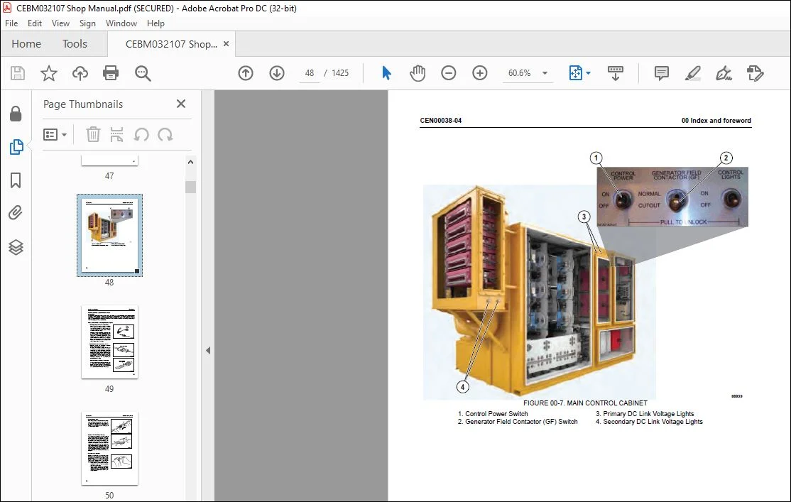
Auxiliary control cabinet components 6
Body-up switch 9
Hoist limit switch 10
Heating/air conditioning (HVAC) system CEN10088-01
Basic air conditioning system operation 3
HVAC components 5
Automatic lubrication (auto lube) system CEN10080-00
General information 3
System operation 4
Engine emissions aftertreatment system CEN10083-01
About emissions aftertreatment 4
DEF injection system 4
DEF heating system 4
Sensors 4
Exhaust system cleaning 5
Inducement strategy 5
20 Standard value table
Standard value table CEN20008-00
Standard value table for truck 3
30 Testing and adjusting
Steering, hoist and auxiliary hydraulic systems CEN30096-03
Hydraulic system bleeddown procedure 3
Hydraulic system vacuum procedure 5
General information on system checkout 6
Hydraulic system checkout procedures 6
Hydraulic system checkout data sheet 17
Toe-in adjustment 20
Hoist cylinder leakage test 21
Steering cylinder leakage test 21
Brake system CEN30097-03
General information on system checkout 3
Brake system checkout procedures 3
Brake system checkout data sheet 15
Service brake conditioning (burnishing) 22
Parking brake adjustment procedure 25
Brake bleeding procedure 26
CEN00040-06 00 Index and foreword
6
Piston assembly return spring force and built-in clearance (BIC) 28
Accumulators and suspensions CEN30098-11
Accumulator charging and storage 3
Bladder accumulator charging procedure 4
Piston accumulator charging procedure 8
Piston accumulator storage 11
Piston accumulator leak testing 11
Checking for improper suspension charge 12
Suspension oiling and charging procedures 13
Suspension pressure test 22
Electrical systems CEN30100-00
General information on system checkout 3
Truck shutdown procedure 4
Required software and tools 4
Electrical system checkout procedures 6
Electrical checkout sheet 10
Interface module (IM) CEN30099-01
Required software and tools 3
Interface module checkout procedures 4
IM checkout sheet 7
KOMTRAX Plus II CEN30091-00
Required software and tools 3
Ethernet connection to KOMTRAX Plus II controller 3
KOMTRAX Plus II configuration 5
GPS connection test 7
Iridium satellite system opening 9
Data download over ethernet connection for KOMTRAX Plus II initialization 11
Payload meter IV CEN30070-03
Payload meter IV software and tools 3
Payload meter IV system configuration 3
Payload meter IV software installation 5
Payload meter IV checkout procedure 6
PLM IV system checkout data sheet 12
Downloading PLM IV data and possible errors 13
Komatsu wireless bridge (KWB) CEN30101-00
General information 3
Required software and tools 3
Configuring the Bullet wireless radio 4
Installing the Bullet wireless radio 7
Configuring the NanoStation access point 8
Testing the connection 11
Changing a service computer’s IP address 12
Cab air conditioning CEN30029-01
General information 3
Service tools and equipment 4
Detecting leaks 7
00 Index and foreword CEN00040-06
7
System performance test 8
Checking system oil 9
System flushing 10
Installing the manifold gauge set 11
Recovering and recycling refrigerant 12
Evacuating the air conditioning system 14
Charging the air conditioning system 15
Automatic lubrication (auto lube) system CEN30089-00
Priming the system 3
Checkout procedure 4
Adjusting the lubrication cycle timing 5
KomVision CEN30105-02
Requirements 3
Initial setup 3
Checkout data sheet 10
Calibration sheets 15
Camera calibration procedures 22
Radar setting procedure 32
Tire monitoring system CEN30114-00
Tire monitoring system software and tools 3
Tire monitoring system configuration 3
Tire monitoring system software installation 5
Tire monitoring system checkout procedure 6
Resetting the tire monitoring system 7
Tire monitoring system checkout data sheet 8
40 Troubleshooting
Fuse, diode and relay locations CEN40197-00
Vehicle Electrical Center (VEC-89) 2
Vehicle Electrical Center (VEC-90) 4
Vehicle Electrical Center (VEC-91) 6
Vehicle Electrical Center (VEC-92) 8
Rear Terminal Mini-fuse and Relay (RTMR3) 9
Rear Terminal Mini-fuse and Relay (RTMR4) 10
Circuit breakers 10
Troubleshooting by fault code, part 1 CEN40178-01
Fault Code A001 4
Fault Code A002 5
Fault Code A003 6
Fault Code A004 7
Fault Code A005 8
Fault Code A006 9
Fault Code A007 10
Fault Code A008 11
Fault Code A011 12
Fault Code A013 13
CEN00040-06 00 Index and foreword
8
Fault Code A014 14
Fault Code A016 15
Fault Code A017 16
Fault Code A018 17
Fault Code A019 18
Fault Code A022 19
Fault Code A101 20
Fault Code A103 21
Fault Code A104 22
Fault Code A105 23
Fault Code A109 24
Fault Code A111 25
Fault Code A115 27
Fault Code A117 28
Fault Code A118: Brake pressure is low while in brake lock 30
Fault Code A123: GE has generated a reduced retarding caution 32
Fault Code A124: GE has generated a no propel / no retard or system not running input 33
Fault Code A125: GE has generated a no propel warning 36
Fault Code A126: Oil level in the hydraulic tank is low 37
Fault Code A127: IM-furnished +5 volt output for sensors is low 38
Fault Code A128: IM-furnished +5 volt output for sensors is high 39
Fault Code A139: Low fuel warning 40
Troubleshooting by fault code, part 2 CEN40179-01
Fault Code A145: Hydraulic oil temp sensors cause engine rpm advance to level 1 4
Fault Code A146: Hydraulic oil temp sensors cause engine rpm advance to level 2 6
Fault Code A152: Starter failure 8
Fault Code A153: Battery voltage is low with the truck in operation 10
Fault Code A154: Battery charging voltage is excessive 13
Fault Code A155: Battery charging voltage is low 14
Fault Code A158: Fuel level sensor open or shorted high; false low fuel level indicated 16
Fault Code A166: Left rear hydraulic oil temperature sensor is low 18
Fault Code A167: Right rear hydraulic oil temperature sensor is low 20
Fault Code A168: Left front hydraulic oil temperature sensor is low 22
Fault Code A169: Right front hydraulic oil temperature sensor is low 24
Fault Code A170: Left rear hydraulic oil temperature sensor is high 26
Fault Code A171: Right rear hydraulic oil temperature sensor is high 27
Fault Code A172: Left front hydraulic oil temperature sensor is high 28
Fault Code A173: Right front hydraulic oil temperature sensor is high 29
Fault Code A184: The J1939 data link is not connected 30
Fault Code A190: The auto lube control has detected an incomplete lube cycle 32
Fault Code A193: Hydraulic Tank Oil Temperature is high 34
Fault Code A194: Left front hydraulic oil temperature is high 35
Fault Code A195: Right front hydraulic oil temperature is high 36
Fault Code A196: Left rear hydraulic oil temperature is high 37
Fault Code A197: Right rear hydraulic oil temperature is high 38
Fault Code A198: Hoist Pressure 1 Sensor is high 39
00 Index and foreword CEN00040-06
9
Fault Code A199: Hoist Pressure 2 Sensor is high 40
Fault Code A200: Steering Pressure Sensor High 41
Fault Code A201: Brake Pressure Sensor High 42
Fault Code A202: Hoist Pressure 1 Sensor Low 44
Fault Code A203: Hoist Pressure 2 Sensor Low 46
Fault Code A204: Steering Pressure Sensor Low 48
Fault Code A205: Brake Pressure Sensor Low 50
Fault Code A206: Ambient Temperature Sensor High 52
Fault Code A207: Ambient Temperature Sensor Low 53
Fault Code A213: Parking brake should have applied; detected as not having applied 54
Fault Code A214: Parking brake should have released; detected as not having released 60
Fault Code A215: Brake auto apply valve circuit is defective 66
Fault Code A216: Open or short to ground detected in parking brake command valve circuit70
Fault Code A223: Excessive engine cranking occurred or jump start attempted 74
Fault Code A230: Parking brake has been requested while truck still moving 76
Fault Code A231: The body is up while traveling or intending to travel 80
Fault Code A233: Drive system CAN/RPC Control Link not connected 84
Fault Code A235: Steering accumulator is in the process of being bled down 88
Fault Code A236: The steering accumulator has not properly bled after 90 seconds 90
Fault Code A237: The CAN/RPC connection to the display is open 92
Fault Code A240: The keyswitch input to the Interface Module is open 93
Fault Code A242: The fuel level gauge in the display panel is defective 94
Fault Code A243: The engine coolant temp gauge in the display panel is defective 95
Fault Code A244: The drive system temp gauge in the dash display panel is defective 96
Fault Code A245: The hydraulic oil temp gauge in the display panel is defective 97
Fault Code A246: PLM reports truck overload 98
Troubleshooting by fault code, part 3 CEN40180-02
Fault Code A247: Low steering pressure warning 4
Fault Code A248: Status module within the dash display panel is defective 7
Fault Code A249: Red warning lamp in the display panel is shorted 9
Fault Code A250: Battery voltage is low with the truck parked 11
Fault Code A251: Sonalert circuit is open or shorted to ground 15
Fault Code A252: Start enable output circuit is either open or shorted to ground 17
Fault Code A253: Steering bleed circuit is not open while running 19
Fault Code A256: Red warning lamp in the display panel is open 21
Fault Code A257: Payload CAN/RPC is not connected 23
Fault Code A258: Steering accumulator bleed pressure switch circuit is defective 24
Fault Code A260: Parking brake failure 25
Fault Code A261: Low brake accumulator pressure warning 27
Fault Code A262: Steering bleed valve circuit open during shutdown 31
Fault Code A264: Parking brake relay circuit is defective 34
Fault Code A265: Service brake failure 37
Fault Code A266: Shift lever was not in park while attempting to crank engine 39
Fault Code A267: Parking brake was not set while attempting to crank engine 41
Fault Code A268: Secondary engine shutdown while cranking 43
Fault Code A270: Brake lock switch power supply is not on when required 45
CEN00040-06 00 Index and foreword
10
Fault Code A272: Brake lock switch power supply is not off when required 48
Fault Code A273: Hoist filter or steering filter pressure switch circuit fault detected 51
Fault Code A274: A brake setting fault has been detected 52
Fault Code A275: A starter has been detected as engaged without a cranking attempt 55
Fault Code A277: Parking brake applied while loading 57
Fault Code A278: Service brake applied while loading 59
Fault Code A279: Low Steering Pressure Switch bad 61
Fault Code A280: Steering accumulator bleed down switch is defective 63
Fault Code A281: Brake lock degrade switch is defective 65
Fault Code A282: Excessive cranking counts or jump starts without the engine running 67
Fault Code A283: Engine shutdown delay aborted; parking brake not set 69
Fault Code A284: Engine shutdown delay aborted; secondary shutdown switch operated 73
Fault Code A285: The parking brake was not set when the keyswitch was turned off 77
Fault Code A286: A fault was detected in the shutdown delay relay circuit 79
Fault Code A292: Shutdown delay relay stays on after latched key switch circuit is off 81
Troubleshooting by fault code, part 4 CEN40181-03
Fault Code A303: Shift lever is defective 4
Fault Code A304: Auto lube grease level fault 6
Fault Code A305: Auto lube circuit is defective 7
Fault Code A307: Both GE inverters are disabled 8
Fault Code A309: No brakes applied when expected 10
Fault Code A310: Low fuel warning 12
Fault Code A311: Brake lock switch is on when it should not be 14
Fault Code A312: DC-DC converter 12 volt circuit sensing is producing low readings 16
Fault Code A313: DCDC converter 12 volt circuit sensing is producing high readings 17
Fault Code A315: DCDC converter 12 volt circuit is low 18
Fault Code A316: Starter engagement has been attempted with engine running 20
Fault Code A317: Operation of brake auto apply circuit without a detected response 22
Fault Code A318: Unexpected power loss to interface module 24
Fault Code A328: Drive system not powered up 25
Fault Code A332: Seat belt not buckled 26
Fault Code A333: The hydraulic ladder controller has declared a ladder fault 28
Fault Code A334: Shift lever not in park when propel was either not ready or at rest 30
Fault Code A335: Manual/Auto Apply Pressure Fault 32
Fault Code A337: Engine Air Filter Circuit Fault 33
Fault Code A338: Engine Air Filter Fault 34
Fault Code A339: The DEF level gauge in the display panel is defective 35
Fault Code A340: The shifter controller has declared a fault 36
Fault Code A341: The shifter control circuit is defective 37
Fault Code A342: The Accessory Pump Filter Switch has actuated 39
Fault Code A343: Truck speed is limited by GE 40
Fault Code A344: GE has posted a No Retarding fault 41
Fault Code A345: Engine speed limited by GE 42
Fault Code A346: Delayed Shut Down by GE 43
Fault Code A347: Operator Override of GE is active 44
Fault Code A348: GE has disabled load box operation 45
00 Index and foreword CEN00040-06
11
Fault Code A349: GE has limited load box operation 46
Fault Code A350: Overload on output 1B 47
Fault Code A351: Overload on output 1E 49
Fault Code A352: Overload on output 1H 51
Fault Code A353: Overload on output 1J 53
Fault Code A354: Overload on output 1K 55
Fault Code A355: Overload on output 1L 56
Fault Code A356: Overload on output 1M 57
Fault Code A357: Overload on output 1N 59
Fault Code A358: Overload on output 1P 61
Fault Code A359: Overload on output 1R 63
Fault Code A360: Overload on output 1S 65
Fault Code A361: Overload on output 1T 66
Fault Code A362: Overload on output 1U 67
Fault Code A363: Overload on output 1X 68
Fault Code A364: Overload on output 1Y 69
Fault Code A365: Overload on output 1Z 70
Fault Code A366: Axle box cooling fault 71
Troubleshooting by fault code, part 5 CEN40182-00
Fault Code A400: Tire 1 (Front Left) High Pressure RED 4
Fault Code A401: Tire 1 (Front Left) High Pressure AMBER 5
Fault Code A402: Tire 1 (Front Left) Low Pressure RED 6
Fault Code A403: Tire 1 (Front Left) Low Pressure AMBER 7
Fault Code A404: Tire 1 (Front Left) No Data / Sensor Failure / Not Connected 8
Fault Code A405: Tire 1 (Front Left) High Temperature RED 9
Fault Code A406: Tire 1 (Front Left) High Temperature AMBER 10
Fault Code A407: Tire 1 (Front Left) Bad Value Sensor Error / Not Connected 11
Fault Code A408: Tire 2 (Front Right) High Pressure RED 12
Fault Code A409: Tire 2 (Front Right) High Pressure AMBER 13
Fault Code A410: Tire 2 (Front Right) Low Pressure RED 14
Fault Code A411: Tire 2 (Front Right) Low Pressure AMBER 15
Fault Code A412: Tire 2 (Front Right) No Data / Sensor Failure / Not Connected 16
Fault Code A413: Tire 2 (Front Right) High Temperature RED 17
Fault Code A414: Tire 2 (Front Right) High Temperature AMBER 18
Fault Code A415: Tire 2 (Front Right) Bad Value Sensor Error / Not Connected 19
Fault Code A416: Tire 3 (Rear Left Outboard) High Pressure RED 20
Fault Code A417: Tire 3 (Rear Left Outboard) High Pressure AMBER 21
Fault Code A418: Tire 3 (Rear Left Outboard) Low Pressure RED 22
Fault Code A419: Tire 3 (Rear Left Outboard) Low Pressure AMBER 23
Fault Code A420: Tire 3 (Rear Left Outboard) No Data / Sensor Failure / Not Connected 24
Fault Code A421: Tire 3 (Rear Left Outboard) High Temperature RED 25
Fault Code A422: Tire 3 (Rear Left Outboard) High Temperature AMBER 26
Fault Code A423: Tire 3 (Rear Left Outboard) Bad Value Sensor Error / Not Connected 27
Fault Code A424: Tire 4 (Rear Left Inboard) High Pressure RED 28
Fault Code A425: Tire 4 (Rear Left Inboard) High Pressure AMBER 29
Fault Code A426: Tire 4 (Rear Left Inboard) Low Pressure RED 30
CEN00040-06 00 Index and foreword
12
Fault Code A427: Tire 4 (Rear Left Inboard) Low Pressure AMBER 31
Fault Code A428: Tire 4 (Rear Left Inboard) No Data / Sensor Failure / Not Connected 32
Fault Code A429: Tire 4 (Rear Left Inboard) High Temperature RED 33
Fault Code A430: Tire 4 (Rear Left Inboard) High Temperature AMBER 34
Fault Code A431: Tire 4 (Rear Left Inboard) Bad Value Sensor Error / Not Connected 35
Fault Code A432: Tire 5 (Rear Right Inboard) High Pressure RED 36
Fault Code A433: Tire 5 (Rear Right Inboard) High Pressure AMBER 37
Fault Code A434: Tire 5 (Rear Right Inboard) Low Pressure RED 38
Fault Code A435: Tire 5 (Rear Right Inboard) Low Pressure AMBER 39
Fault Code A436: Tire 5 (Rear Right Inboard) No Data / Sensor Failure / Not Connected 40
Fault Code A437: Tire 5 (Rear Right Inboard) High Temperature RED 41
Fault Code A438: Tire 5 (Rear Right Inboard) High Temperature AMBER 42
Fault Code A439: Tire 5 (Rear Right Inboard) Bad Value Sensor Error / Not Connected 43
Fault Code A440: Tire 6 (Rear Right Outboard) High Pressure RED 44
Fault Code A441: Tire 6 (Rear Right Outboard) High Pressure AMBER 45
Fault Code A442: Tire 6 (Rear Right Outboard) Low Pressure RED 46
Fault Code A443: Tire 6 (Rear Right Outboard) Low Pressure AMBER 47
Fault Code A444: Tire 6 (Rear Right Outboard) No Data / Sensor Failure / Not Connected 48
Fault Code A445: Tire 6 (Rear Right Outboard) High Temperature RED 49
Fault Code A446: Tire 6 (Rear Right Outboard) High Temperature AMBER 50
Fault Code A447: Tire 6 (Rear Right Outboard) Bad Value Sensor Error / Not Connected 51
Aftertreatment system fault codes CEN40222-02
Fault Code CA256 5
Fault Code CA1677 7
Fault Code CA1678 9
Fault Code CA1682 12
Fault Code CA1683 19
Fault Code CA1684 21
Fault Code CA1685 23
Fault Code CA1686 25
Fault Code CA1712 27
Fault Code CA1713 29
Fault Code CA1714 31
Fault Code CA1715 32
Fault Code CA1887 34
Fault Code CA2771 35
Fault Code CA3142 39
Fault Code CA3143 41
Fault Code CA3146 43
Fault Code CA3147 45
Fault Code CA3232 47
Fault Code CA3497 50
Fault Code CA3498 51
Fault Code CA3547 52
Fault Code CA3558 53
Fault Code CA3559 55
00 Index and foreword CEN00040-06
13
Fault Code CA3562 57
Fault Code CA3563 59
Fault Code CA3567 61
Fault Code CA3571 63
Fault Code CA3572 65
Fault Code CA3573 68
Fault Code CA3574 70
Fault Code CA3575 72
Fault Code CA3712 74
Fault Code CA3713 75
Fault Code CA3714 78
Fault Code CA3867 79
Fault Code CA3868 81
Fault Code CA3878 84
Fault Code CA3988 85
Fault Code CA3995 89
Fault Code CA4113 91
Fault Code CA4114 93
Fault Code CA4119 95
Fault Code CA4121 97
Fault Code CA4152 99
Fault Code CA4164 103
Fault Code CA4165 105
Fault Code CA4166 108
Fault Code CA4168 110
Fault Code CA4169 112
Fault Code CA4174 114
Fault Code CA4175 116
Fault Code CA4233 119
Fault Code CA4234 120
Fault Code CA4243 121
Fault Code CA4277 122
Fault Code CA4457 124
Fault Code CA4458 126
Fault Code CA4459 129
Fault Code CA4461 131
Fault Code CA4462 133
Fault Code CA4464 135
Fault Code CA4465 137
Fault Code CA4466 140
Fault Code CA4467 147
Fault Code CA4474 149
Fault Code CA4475 151
Fault Code CA4572 154
Fault Code CA4677 158
Fault Code CA4679 162
CEN00040-06 00 Index and foreword
14
Fault Code CA4682 163
Fault Code CA4731 164
Fault Code CA4732 165
Fault Code CA4736 166
Fault Code CA4737 167
Fault Code CA4738 168
Fault Code CA4739 169
Fault Code CA4745 170
Fault Code CA4768 171
Fault Code CA4769 173
Fault Code CA4842 175
Fault Code CA4863 176
Fault Code CA4947 177
Fault Code CA5115 178
Fault Code CA5116 181
Fault Code CA5117 184
Fault Code CA5247 187
Fault Code CA5653 189
Fault Code CA5654 192
Fault Code CA5725 194
Fault Code CA5727 199
Fault Code CA5728 202
Fault Code CA5729 205
Fault Code CA5748 207
Fault Code CA5749 209
Fault Code CA5751 211
Fault Code CA5753 213
Fault Code CA5755 216
Fault Code CA5756 221
Fault Code CA5758 223
Fault Code CA5768 225
Fault Code CA5769 227
Fault Code CA5771 230
Fault Code CA5772 232
Fault Code CA5773 235
Fault Code CA5774 238
Fault Code CA5775 240
Fault Code CA5776 245
Fault Code CA5778 247
Fault Code CA5779 249
Fault Code CA5887 251
Fault Code CA5888 252
Fault Code CA5889 253
Fault Code CA5891 254
Fault Code CA5892 255
Fault Code CA5893 256
00 Index and foreword CEN00040-06
15
Fault Code CA6692 257
Fault Code CA6693 259
Fault Code CA6694 261
Fault Code CA6695 263
Fault Code CA6696 265
Fault Code CA6697 267
Fault Code CA6855 269
Fault Code CA6856 272
Steering system CEN40198-01
Steering circuit troubleshooting chart 2
Steering circuit troubleshooting guidelines 6
Basic hydraulic system checks 7
System leakage check 8
Steering pump troubleshooting guide 10
Pump pressure control checks 13
KomVision CEN40200-01
KomVision fault codes 3
Automatic lubrication (auto lube) system CEN40202-00
Autolube troubleshooting chart 3
Heating/air conditioning (HVAC) system CEN40226-00
Control panel configurations 3
Diagnostics mode 4
Additional HVAC troubleshooting chart 5
Voltage levels 7
Electronic fan clutch CEN40256-00
Electronic fan clutch troubleshooting 3
50 Disassembly and assembly
Service tools CEN50074-05
Special tool group 3
Additional service tools 4
Locally made tools 5
Wheels, spindles and rear axle CEN50075-05
General precautions for tires and rims 3
Rim components 4
Wheel stud maintenance 5
Removal and installation of front wheel 6
Removal and installation of rear wheel 8
Rim and tire service 11
Removal and installation of front wheel hub and spindle 28
Disassembly and assembly of front wheel hub and spindle 35
Hub floating ring seal assembly and installation 45
Removal and installation of rear axle 52
Removal and installation of anti-sway bar 55
Removal and installation of pivot pin 58
Pivot eye and bearing service 60
CEN00040-06 00 Index and foreword
16
Removal and installation of wheel motor 62
Brake system CEN50076-05
Removal and installation of brake valve 3
Disassembly and assembly of brake valve/pedal assembly 6
Removal and installation of brake manifold 9
Disassembly and assembly of brake manifold 11
Disassembly and assembly of brake accumulator 12
Removal and installation of front brake caliper 16
Disassembly and assembly of front brake caliper 18
Removal and installation of rear brake caliper 21
Disassembly and assembly of rear brake caliper 28
Steering system CEN50080-02
Removal and installation of steering control unit 3
Disassembly and assembly of steering control unit 5
Removal and installation of steering column 10
Removal and installation of steering wheel 12
Removal and installation of bleeddown manifold 13
Removal and installation of flow amplifier 14
Removal and installation of steering cylinders and tie rod 16
Disassembly and assembly of steering cylinders 18
Removal and installation of steering/brake pump 21
Removal and installation of piston steering accumulator 23
Disassembly and assembly of piston steering accumulator 26
Suspensions CEN50081-02
General information 3
Removal and installation of front suspension 3
Disassembly and assembly of front suspension 11
Removal and installation of rear suspension 15
Disassembly and assembly of rear suspension 19
Hoist circuit CEN50082-03
Removal and installation of hoist pump 3
Disassembly and assembly of hoist pump 8
Removal and installation of hoist valve 17
Disassembly and assembly of hoist valve 19
Overcenter manifold service 26
Removal and installation of hoist pilot valve 27
Disassembly and assembly of hoist pilot valve 28
Removal and installation of hoist cylinders 32
Disassembly and assembly of hoist cylinders 35
Body and structures CEN50083-03
Removal and installation of dump body 3
Removal and installation of body pads 6
Removal and installation of diagonal ladder/hood and grille assembly 8
Removal and installation of RH deck 10
Removal and installation of LH deck 12
Removal and installation of fuel tank 14
00 Index and foreword CEN00040-06
17
Removal and installation of fuel gauge sender 16
Removal and installation of hydraulic tank 17
Removal and installation of hydraulic tank strainers 19
Operator cab CEN50079-02
Removal and installation of operator cab 3
Removal and installation of cab door 6
Disassembly and assembly of cab door 8
Adjustment of cab door 16
Removal and installation of side window glass 18
Removal and installation of windshield and rear window glass 21
Removal and installation of windshield wiper components 22
Removal and installation of cab seats 24
Removal and installation of seat belts 26
Power module CEN50118-04
Removal and installation of power module 3
Exhaust tube installation 16
Exhaust blanket installation 16
Removal and installation of alternator 17
Removal and installation of radiator 33
Repairing the radiator 38
Removal and installation of engine 42
Removal and installation of electronic fan clutch 44
Removal and installation of electronic fan clutch speed sensor 45
90 Diagrams and drawings
Hydraulic circuit diagrams CEN90025-01
Steering and hoist hydraulic circuit diagram 58E-60-02431
Brake hydraulic circuit diagram 58E-60-50030
Auxiliary system hydraulic circuit schematic 58E-60-01680
Electrical circuit diagrams CEN90026-01
Electrical circuit diagram 58E-06-02316
HVAC electrical circuit diagram 58B-06-06830
Need help? Contact: [email protected]
https://vimeo.com/742178876
DESCRIPTION:
Komatsu 830E-5 Dump Truck Shop Manual CEBM032107 – PDF DOWNLOAD
SERIAL NUMBERS 830E-5 A50005 and up
ENGINE 16V160
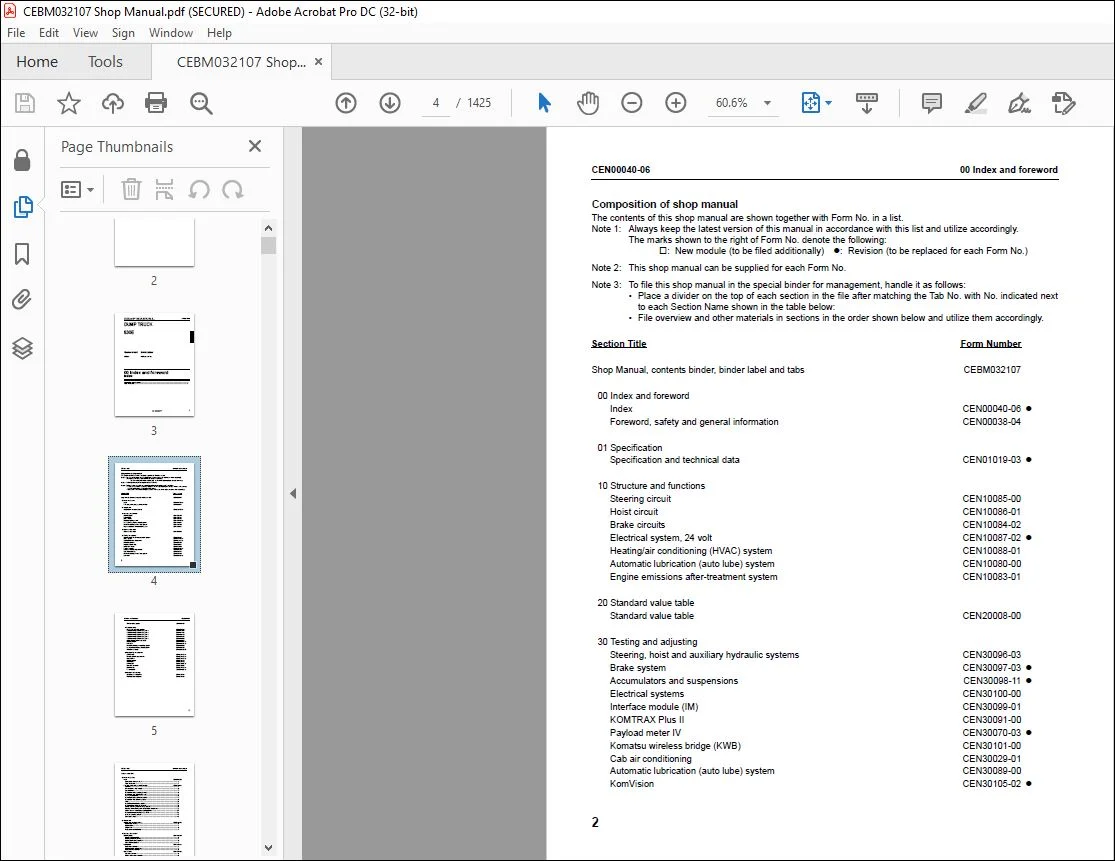
Composition of shop manual:
The contents of this shop manual are shown together with Form No. in a list.
Note 1: Always keep the latest version of this manual in accordance with this list and utilize accordingly.
The marks shown to the right of Form No. denote the following:
: New module (to be filed additionally) : Revision (to be replaced for each Form No.)
Note 2: This shop manual can be supplied for each Form No.
Note 3: To file this shop manual in the special binder for management, handle it as follows:
• Place a divider on the top of each section in the file after matching the Tab No. with No. indicated next
to each Section Name shown in the table below:
• File overview and other materials in sections in the order shown below and utilize them accordingly.
PLEASE NOTE:
- This is the SAME exact manual used by your dealers to fix your vehicle.
- The same can be yours in the next 2-3 mins as you will be directed to the download page immediately after paying for the manual.
- Any queries / doubts regarding your purchase, please feel free to contact [email protected]
S.V


