Komatsu 830E Dump Truck Operation & Maintenance Manual A30733 & UP – PDF DOWNLOAD
Original price was: $50.95.$15.95Current price is: $15.95.
Komatsu 830E Dump Truck Operation & Maintenance Manual
Book Code: CEAM015001
SERIAL NUMBERS A30733 & UP
Description
Komatsu 830E Dump Truck Operation & Maintenance Manual
FILE DETAILS:
Komatsu 830E Dump Truck Operation & Maintenance Manual
Language : English
Pages : 154
Downloadable : Yes
File Type : PDF
Size: 2.54 MB
Book Code: CEAM015001
KOMATSU 830E DUMP TRUCK OPERATION & MAINTENANCE MANUAL A30733 & UP – PDF DOWNLOAD:
DESCRIPTION:
Komatsu 830E Dump Truck Operation & Maintenance Manual
FOREWORD:
This manual is written for use by the operator and/or the service technician. It is designed to help these persons to become fully knowledgeable of the truck and all of its systems in order to keep it operating safely and efficiently. All operators and maintenance personnel should read and understand the information in this manual before operating the truck or performing maintenance and/or operational checks on the truck. All safety notices, warnings, and cautions should be understood and followed when operating the truck or performing repairs on the truck.
- The first section covers component descriptions, truck specifications and safe work practices, as well as other general information. The major portion of the manual pertains to disassembly, service and reassembly. Each major serviceable area is dealt with individually. For example, the disassembly, service and reassembly of the radiator group is discussed as a unit. The same is true of the engine and engine accessories, and so on through the entire mechanical detail of the truck.
- Disassembly should be carried only as far as necessary to accomplish needed repairs. The illustrations used in this manual are typical of the component shown and may not be an exact reproduction of what is found on the truck. This manual shows dimensioning of U.S. standard and metric (SI) units throughout.
- All references to “right,” “left,” “front,” or “rear” are made with respect to the operator’s normal seated position unless specifically stated otherwise. When assembly instructions are provided without references to specific torque values, standard torque values should be used.
- Standard torque values are shown in torque charts later in this section. Specific torques, when provided in the text, are in bold face type, such as 135 N·m (100 ft lb). All torque specifications have ±10% tolerance unless otherwise specified.
- A product identification plate is located on the frame in front of the right side front wheel. It designates the Truck Model Number, Product Identification Number (vehicle serial number), and Maximum GVW (Gross Vehicle Weight) rating. The KOMATSU truck model designation consists of three numbers and one letter (i.e. 960E). The three numbers represent the basic truck model. The letter “E” designates an Electrical wheel motor drive system.
- The Product Identification Number (vehicle serial number) contains information which identifies several characteristics of this unit. For a more detailed explanation, refer to the Operation and Maintenance Manual. The Gross Vehicle Weight (GVW) is what determines the load on the drive train, frame, tires, and other components.
- The vehicle design and application guidelines are sensitive to the maximum GVW. GVW is total weight: empty vehicle weight + fuel & lubricants + payload. To determine the allowable payload, fill all lubricants to the proper level and fill the fuel tank of an empty truck (which includes all accessories, body liners, tailgates, etc.), and then weigh the truck. Record this value and subtract it from the GVW. The result is the allowable payload.
TABLE OF CONTENTS:
Komatsu 830E Dump Truck Operation & Maintenance Manual
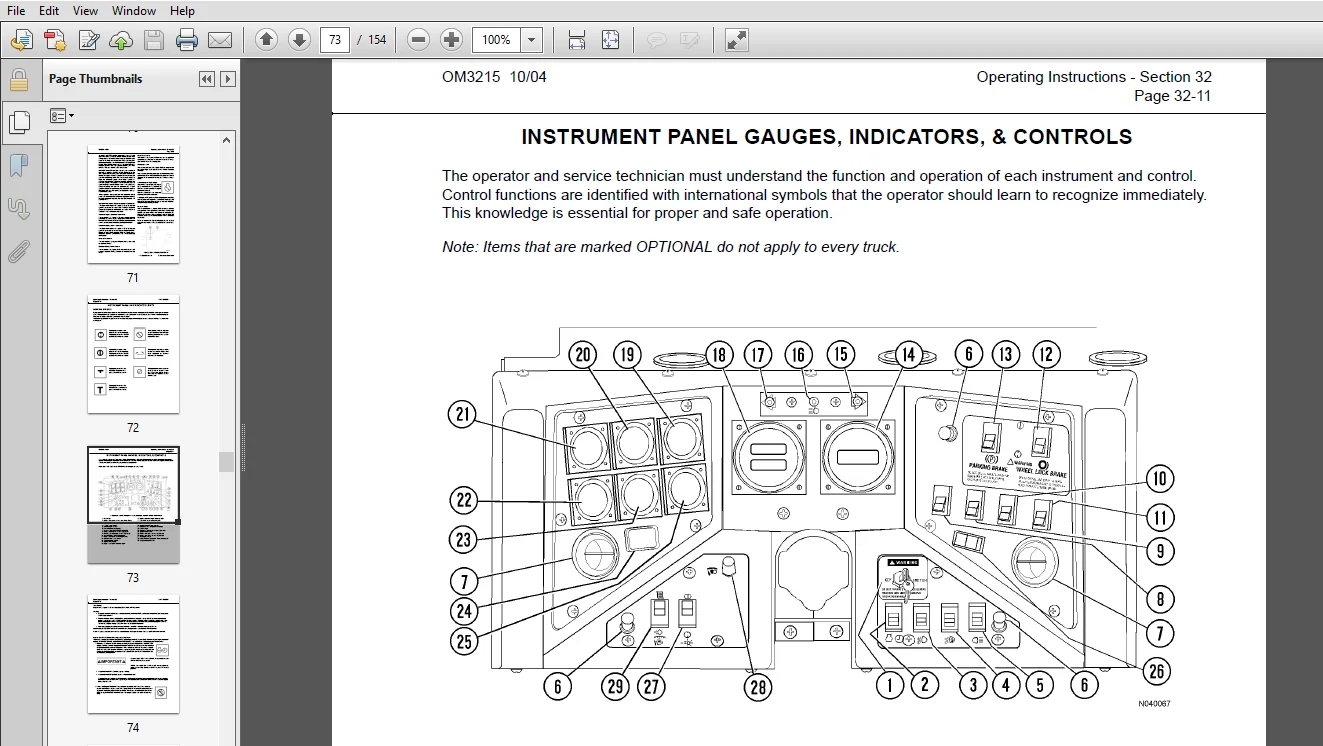
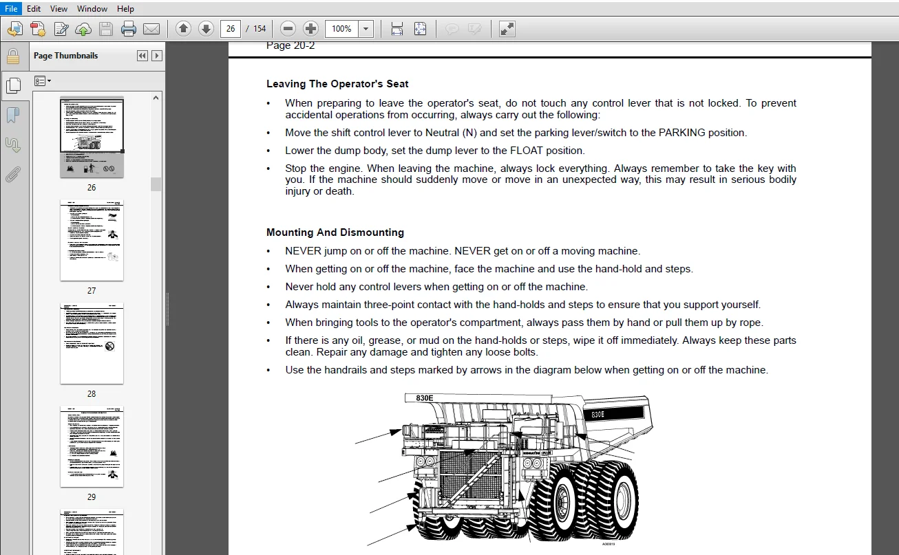
MAIN MENU.........................................................................................  0
COVER.............................................................................................  1
INTRODUCTION......................................................................................  7
	FOREWORD......................................................................................  7
	ALERTS PAGE...................................................................................  8
	TRUCK MODEL ILLUSTRATION...................................................................... 16
	ABOUT THIS MANUAL............................................................................. 17
	WARNINGS......................................................................................  3
	STANDARD CHARTS AND TABLES.................................................................... 19
TABLE OF CONTENTS.................................................................................  9
GENERAL SAFETY.................................................................................... 25
	Safety Rules.................................................................................. 25
	Safety Features............................................................................... 25
	Clothing And Personal Items................................................................... 25
	Unauthorized Modification..................................................................... 25
	Leaving The Operator's Seat................................................................... 26
	Mounting And Dismounting...................................................................... 26
	Fire Prevention For Fuel And Oil.............................................................. 26
	Precautions With High Temperature Fluids...................................................... 27
	Asbestos Dust Hazard Prevention............................................................... 27
	Prevention Of Injury By Work Equipment........................................................ 27
	Fire Extinguisher And First Aid Kit........................................................... 27
	Precautions When Using Rops................................................................... 28
	Precautions For Attachments................................................................... 28
	Precautions For Starting Machine.............................................................. 28
	PRECAUTIONS DURING OPERATION.................................................................. 29
		Safety Is Thinking Ahead.................................................................. 29
		Safety At The Worksite.................................................................... 29
		Fire Prevention........................................................................... 29
		Preparing For Operation................................................................... 29
		Ventilation In Enclosed Areas............................................................. 29
		In Operator's Cab - Before Starting The Engine............................................ 30
		Mirrors, Windows, And Lights.............................................................. 30
		OPERATING THE MACHINE..................................................................... 30
			When Starting The Engine.............................................................. 30
			Truck Operation - General............................................................. 30
			Check When Traveling In Reverse....................................................... 31
			Traveling............................................................................. 31
			Traveling On Slopes................................................................... 32
			Ensure Good Visibility................................................................ 32
			Operate Carefully On Snow............................................................. 32
			Avoid Damage To Dump Body............................................................. 32
			Driving Near High-voltage Cables...................................................... 32
			When Dumping.......................................................................... 33
			Working On Loose Ground............................................................... 33
			When Loading.......................................................................... 33
			Parking The Machine................................................................... 33
		TOWING.................................................................................... 33
		WORKING NEAR BATTERIES.................................................................... 34
			Battery Hazard Prevention............................................................. 34
			Starting With Booster Cables.......................................................... 34
		PRECAUTIONS FOR MAINTENANCE............................................................... 35
			BEFORE PERFORMING MAINTENANCE......................................................... 35
				Warning Tag....................................................................... 35
				Proper Tools...................................................................... 35
				Stopping The Engine Before Service................................................ 35
				Securing The Dump Body............................................................ 35
			DURING MAINTENANCE.................................................................... 36
				Personnel......................................................................... 36
				Attachments....................................................................... 36
				Work Under The Machine............................................................ 36
				Keep The Machine Clean............................................................ 36
				Rules To Follow When Adding Fuel Or Oil........................................... 36
				Radiator Water Level.............................................................. 37
				Use Of Lighting................................................................... 37
				Precautions With The Battery...................................................... 37
				Handling High-pressure Hoses...................................................... 37
				Precautions With High Pressure Oil................................................ 37
				Precautions When Performing Maintenance Near High Temperature Or High Pressure.... 38
				Rotating Fan And Belts............................................................ 38
				Waste Materials................................................................... 38
			TIRES................................................................................. 39
				Handling Tires.................................................................... 39
				Storing Tires After Removal....................................................... 39
		ADDITIONAL JOB SITE RULES................................................................. 40
		WHEN REPAIRS ARE NECESSARY................................................................ 41
WARNINGS AND CAUTIONS............................................................................. 43
OPERATING INSTRUCTIONS............................................................................ 51
	PREPARING FOR OPERATION....................................................................... 51
		Safety Is Thinking Ahead.................................................................. 51
		At The Truck - Ground Level Walk Around Inspection........................................ 51
	ENGINE START-UP SAFETY PRACTICES.............................................................. 54
	AFTER ENGINE HAS STARTED...................................................................... 55
	MACHINE OPERATION SAFETY PRECAUTIONS.......................................................... 55
	LOADING....................................................................................... 56
	HAULING....................................................................................... 56
	PASSING....................................................................................... 56
	DUMPING....................................................................................... 57
		To Raise Body:............................................................................ 57
		To Lower Body: When dumping over a berm or into a crusher:................................ 57
		To Lower Body: When dumping on flat ground:............................................... 58
	TOWING........................................................................................ 58
	SUDDEN LOSS OF ENGINE POWER................................................................... 59
	SAFE PARKING PROCEDURES....................................................................... 59
	ENGINE SHUTDOWN PROCEDURE..................................................................... 59
	DELAYED ENGINE SHUTDOWN PROCEDURE............................................................. 60
	RESERVE ENGINE OIL SYSTEM (Optional).......................................................... 61
		Operation................................................................................. 61
		LED Monitor Light......................................................................... 61
		Changing Oil.............................................................................. 61
OPERATOR CAB AND CONTROLS......................................................................... 63
	STEERING WHEEL AND CONTROLS................................................................... 64
		Horn Button............................................................................... 64
		Tilt / Telescope Lever.................................................................... 64
		Multi-function Turn Signal Switch......................................................... 64
		Turn Signal Operation..................................................................... 64
		High Beam Headlight Operation............................................................. 64
		Windshieldindshield Wiper Operation....................................................... 64
	PEDALS........................................................................................ 65
		Service Brake Pedal....................................................................... 65
		Dynamic Retarder Pedal.................................................................... 65
		Optional - Dual Function / Single Pedal................................................... 65
		Throttle Pedal............................................................................ 65
	HEATER / AIR CONDITIONER COMPARTMENT AND CONTROLS............................................. 66
		Defroster Vent Control Switch............................................................. 66
		Heat Vent Control Switch.................................................................. 66
		Temperature Control Knob.................................................................. 66
		Fan Control Knob.......................................................................... 66
		Heater/air Conditioner Selector Switch.................................................... 66
		Heater/air Conditioner Vents.............................................................. 66
	OVERHEAD PANEL AND DISPLAY.................................................................... 67
		Grade/speed Warning Chart................................................................. 67
		Radio Speakers............................................................................ 67
		Warning Alarm Buzzer...................................................................... 67
		Cab Radio................................................................................. 67
		Warning Lights Dimmer Control............................................................. 67
		Status / Warning Indicator Light Panel.................................................... 67
		Windshield Wipers......................................................................... 67
		Air Cleaner Vacuum Gauges................................................................. 68
	CENTER CONSOLE................................................................................ 68
		F-n-r Selector Switch..................................................................... 68
		Hoist Control Lever....................................................................... 69
		To Raise Body:............................................................................ 69
		To Lower Body:............................................................................ 69
		Ash Tray.................................................................................. 69
		Lighter................................................................................... 69
		L.h. Window Control Switch................................................................ 69
		R.h. Window Control Switch................................................................ 69
		Engine Shutdown Switch.................................................................... 69
		Override Switch........................................................................... 70
		Retard Speed Control (RSC) Off/on Switch.................................................. 70
		Retard Speed Control (RSC) Adjust Dial.................................................... 70
		Statex III Propulsion System Diagnostic Connector......................................... 71
		Komatsu Engine Quantum Connector.......................................................... 71
		Komatsu Engine Cense Connector............................................................ 71
		Unused Connector.......................................................................... 71
		Modular Mining Port Conector.............................................................. 71
		Data Store Button......................................................................... 71
		Passenger Seat............................................................................ 71
		Service Engine Light (Blue)............................................................... 71
		Payload Meter............................................................................. 71
	INSTRUMENT PANEL AND INDICATOR LIGHTS......................................................... 72
		CONTROL SYMBOLS........................................................................... 72
	INSTRUMENT PANEL GAUGES, INDICATORS, & CONTROLS............................................... 73
		Key Switch................................................................................ 74
		Starting.................................................................................. 74
		Engine Shutdown Switch With Timer Delay (Optional)........................................ 74
		Fog Lights (Optional)..................................................................... 75
		Ladder Light Switch....................................................................... 75
		Manual Backup Switch...................................................................... 75
		Panel Illumination Lights................................................................. 75
		Cab Air Conditioner / Heater Vents........................................................ 75
		Engine Cold Weather Starting Aid (Optional)............................................... 75
		Rotating Beacon Light Switch (Optional)................................................... 75
		Heated Mirror Switch (Optional)........................................................... 75
		Wheel Brake Lock Control.................................................................. 76
		Parking Brake Control..................................................................... 76
		Tachometer................................................................................ 76
		Right Turn Signal Indicator............................................................... 77
		High Beam Indicator....................................................................... 77
		Left Turn Signal Indicator................................................................ 77
		Speedometer / Payload Meter............................................................... 77
		Voltmeter................................................................................. 77
		Engine Oil Pressure Gauge................................................................. 77
		Water Temperature Gauge................................................................... 77
		Fuel Gauge................................................................................ 77
		Hourmeter................................................................................. 78
		Headlight Switch.......................................................................... 78
		Panel Light Dimmer........................................................................ 78
		Payload Meter Switch...................................................................... 78
		INDICATOR LIGHT SYMBOLS................................................................... 80
			Hazard Warning Lights................................................................. 84
			Lamp Test Switch...................................................................... 84
	OPERATOR COMFORT.............................................................................. 85
		OPERATOR SEAT............................................................................. 85
			Adjustment............................................................................ 85
			Seat Removal.......................................................................... 85
			Seat Installation..................................................................... 86
LUBRICATION AND SERVICE........................................................................... 87
	830E SERVICE CAPACITIES....................................................................... 87
	HYDRAULIC TANK SERVICE........................................................................ 87
		Adding Oil................................................................................ 87
	COOLANT LEVEL CHECK........................................................................... 88
	RADIATOR FILLING PROCEDURE.................................................................... 88
	RESERVE ENGINE OIL SYSTEM (Optional).......................................................... 88
		Reserve Oil Tank Filling Procedure (Remote fill).......................................... 88
	LUBRICATION CHART............................................................................. 89
	10 HOUR (DAILY) INSPECTION.................................................................... 90
		10 HOUR LUBRICATION AND MAINTENANCE CHECKS................................................ 90
			LED Light Signals:.................................................................... 90
	50 HOUR LUBRICATION AND MAINTENANCE CHECKS.................................................... 92
	100 HOUR LUBRICATION AND MAINTENANCE CHECKS................................................... 93
	250 HOUR LUBRICATION AND MAINTENANCE CHECKS................................................... 94
	500 HOUR LUBRICATION AND MAINTENANCE CHECKS................................................... 96
	1000 HOURS LUBRICATION AND MAINTENANCE CHECKS................................................. 97
	2500 HOUR MAIN1TENANCE CHECKS................................................................. 98
	5000 HOUR MAINTENANCE CHECKS.................................................................. 98
	10,000 HOUR MAINTENANCE CHECKS................................................................ 98
AUTOMATIC LUBRICATION SYSTEM...................................................................... 99
	GENERAL DESCRIPTION........................................................................... 99
	SYSTEM COMPONENTS.............................................................................101
		Filter ...................................................................................101
		Hydraulic Motor and Pump .................................................................101
		Grease Reservoir .........................................................................101
		Pressure Reducing Valve...................................................................101
		Flow Control Valve........................................................................101
		Solenoid Valve ...........................................................................101
		Vent Valve................................................................................101
		Lubrication Cycle Timer...................................................................101
		Delay Timer...............................................................................101
		Pump Cutoff Pressure Switch (N.O. 2500 psi [17 237 kPa]) .................................101
		Grease Pressure Failure Switch (N.O. 2000 psi [13 789 kPa])...............................101
		Pressure Gauge............................................................................101
		Injectors.................................................................................101
	SYSTEM OPERATION..............................................................................102
		Normal Operation:.........................................................................102
		Pressure Failure Detection Circuits:......................................................103
		INJECTOR OPERATION........................................................................104
		System Priming............................................................................105
		Filter Assembly...........................................................................105
	LUBRICANT PUMP................................................................................106
		Pump Housing Oil Level....................................................................106
		Pump Pressure Control.....................................................................106
		Pressure Control Valve Adjustment.........................................................106
	INJECTORS (SL-1 Series “H”))..................................................................107
		Injector Specifications...................................................................107
		Injector Adjustment.......................................................................107
	SYSTEM CHECKOUT...............................................................................108
		Lubrication Cycle Timer Check.............................................................108
		Lubrication Cycle Timer Adjustment........................................................108
	SYSTEM TROUBLESHOOTING CHART..................................................................109
	PREVENTATIVE MAINTENANCE PROCEDURES...........................................................111
		Daily Lubrication System Inspection.......................................................111
		250 Hour Inspection.......................................................................111
		1000 Hour Inspection......................................................................111
TRUCK COMPONENT DESCRIPTION.......................................................................113
	SPECIFICATIONS................................................................................115
PAYLOAD METER III.................................................................................117
	OPERATION SECTION.............................................................................119
		Introduction..............................................................................119
		Data Summary..............................................................................119
		Data Gathering............................................................................119
	COMPONENT DESCRIPTION.........................................................................120
		System Diagram............................................................................120
		Suspension Pressure Sensors...............................................................120
		Inclinometer..............................................................................120
		Operator Display..........................................................................120
		Operator Switch...........................................................................121
		Speed Input...............................................................................121
		Body-Up Switch............................................................................121
		Brake Lock Switch.........................................................................121
		Payload Meter.............................................................................121
		Communications Ports......................................................................121
		Keyswitch Input...........................................................................122
		Payload Meter Power.......................................................................122
		Load Lights...............................................................................122
		Wiring and Termination....................................................................123
		TCI Outputs...............................................................................123
	OPERATOR’S DISPLAY AND SWITCH.................................................................124
		Reading the Speedometer...................................................................124
		Reading the Load Display..................................................................124
		Using the Operator ID.....................................................................124
		Using the Load and Ton Counter............................................................124
		Total Ton Counter.........................................................................124
		Total Load Counter........................................................................125
		Clearing the Counters.....................................................................125
		Viewing Live Sensor Data..................................................................125
		Other Display Messages....................................................................125
	PAYLOAD OPERATION & CALCULATION...............................................................126
		Description of Haul Cycle States..........................................................126
		Haul Cycle Description....................................................................126
		Load Calculation..........................................................................127
		Carry Back................................................................................127
		Measurement Accuracy......................................................................127
	SOURCES FOR PAYLOAD ERROR.....................................................................127
		Payload Error.............................................................................127
		Loading Conditions........................................................................128
		Pressure Sensors..........................................................................128
		Swingloads................................................................................128
		Speed and Distance........................................................................128
	HAUL CYCLE DATA...............................................................................128
		Haul Cycle Data...........................................................................129
		Haul Cycle Warning Flags..................................................................130
		A: Continuous Loading.....................................................................130
		B: Loading to Dumping Transition..........................................................130
		C: No Final Load..........................................................................130
		D: Maneuvering to Dumping Transition......................................................130
		E: Average Load or Tare Used..............................................................130
		F: Final Zone to Dumping Transition.......................................................130
		H: False Body Up..........................................................................130
		I: Body Up Signal Failed..................................................................130
		J: Speed Sensor Failed....................................................................130
		K: New Tare Not Calculated................................................................130
		L: Incomplete Haul Cycle..................................................................130
		M: Haul Cycle Too Long....................................................................131
		N: Sensor Input Error.....................................................................131
		Alarm Records.............................................................................131
		Frame Torque Data.........................................................................131
		Sprung Weight Data........................................................................132
		Maximum Speed Data........................................................................132
	PC SOFTWARE OVERVIEW..........................................................................132
		PC Overview...............................................................................132
		System Configuration......................................................................132
		Installing the PLMIII Software............................................................132
	DOWNLOADING DATA..............................................................................133
	PLMIII SYSTEM CONFIGURATION...................................................................134
		Starting Communications...................................................................134
		Displayed Payload Units...................................................................134
		Time Units................................................................................134
		Connection Menu...........................................................................134
		Connecting to the Payload Meter...........................................................135
		Configure the Payload Meter...............................................................135
		Setting the Date and Time.................................................................135
		Setting the Truck Type....................................................................136
		Setting the Gauge Display Units...........................................................136
		Setting the Frame Serial Number...........................................................136
		Setting the Truck Number..................................................................136
		Setting the Komatsu Distributor...........................................................136
		Setting the Komatsu Customer..............................................................136
		Clean Truck Tare..........................................................................137
		Inclinometer Calibration..................................................................137
	DATA ANALYSIS.................................................................................138
		Sorting on Truck Unit Number..............................................................138
		Creating a Query..........................................................................138
		Sorting on Truck Type.....................................................................138
		Sorting on Date Range.....................................................................139
		Sorting on Time Range.....................................................................139
		Payload Detail Screen.....................................................................140
		Creating Reports..........................................................................140
		Summary - one page report.................................................................141
		Detailed - multi-page report..............................................................141
		Creating Graphs...........................................................................142
		Exporting Data............................................................................142
		CSV Export................................................................................142
		Compressed................................................................................143
		To export data in ZIP format:.............................................................144
		Importing Data............................................................................144
		Deleting Haul Cycle Records...............................................................144
		Viewing Alarms............................................................................145
		Deleting Alarm Records....................................................................145
RADIO, AM / FM STEREO CASSETTE....................................................................147
	SETTING THE TIME..............................................................................147
	GENERAL RECEIVER FUNCTIONS....................................................................147
		Turning The Power On And Off..............................................................147
		Display...................................................................................147
		Setting The Default Display...............................................................148
		Adjusting Display Brightness..............................................................148
	OPERATING THE RADIO...........................................................................148
		BAND......................................................................................148
		TUNE/SEEK.................................................................................148
		Manual Tuning.............................................................................148
		SEEK Mode.................................................................................148
		SCAN......................................................................................148
		AUTO......................................................................................148
	ADJUSTING THE RECEIVER SETTINGS...............................................................149
	PROGRAMMING PRESET STATIONS...................................................................149
	OPERATION OF THE WEATHERBAND (U.S.)...........................................................149
	SATELLITE RADIO...............................................................................150
		Operating Satellite Radio.................................................................150
		Program Type Search (PTY).................................................................150
	CASSETTE PLAYER...............................................................................151
		Playing A Cassette........................................................................151
		Cassette Functions........................................................................151
	PROGRAMMABLE EJECT DEFAULT....................................................................151
		Bad Tape Detect...........................................................................152
	CASSETTE PLAYER CLEANING......................................................................152
IMAGES PREVIEW OF THE MANUAL:
PLEASE NOTE:
- This is the SAME MANUAL used by the dealerships to diagnose your vehicle
- No waiting for couriers / posts as this is a PDF manual and you can download it within 2 minutes time once you make the payment.
- Your payment is all safe and the delivery of the manual is INSTANT – You will be taken to the DOWNLOAD PAGE.
- So have no hesitations whatsoever and write to us about any queries you may have : heydownloadss @gmail.com


