Komatsu 860E-1KT DUMP TRUCK Shop Manual CEBM022007 – PDF DOWNLOAD
Original price was: $86.95.$37.95Current price is: $37.95.
Komatsu 860E-1KT DUMP TRUCK Shop Manual CEBM022007 – PDF DOWNLOAD
Description
Komatsu 860E-1KT DUMP TRUCK Shop Manual CEBM022007 – PDF DOWNLOAD
IMAGES PREVIEW OF THE MANUAL:
TABLE OF CONTENTS:
Komatsu 860E-1KT DUMP TRUCK Shop Manual CEBM022007 – PDF DOWNLOAD
00 Index and foreword 3
Index 3
Composition of shop manual 4
Table of contents 6
Foreword, safety and general information 35
Foreword 39
How to read the shop manual 40
Composition of shop manual 40
Revision and distribution 40
Symbols 41
General safety 42
Safety rules 42
Safety features 42
Fire extinguisher and first aid kit 42
Clothing and personal items 42
Leaving the operator seat 43
Mounting and dismounting 43
Fire prevention for fuel and oil 43
Precautions with high temperature fluids 44
Asbestos dust hazard prevention 44
Prevention of injury by work equipment 44
Unauthorized modification 44
Precautions when using ROPS 44
Precautions for attachments 45
Precautions for starting the truck 45
Precautions before operating the truck 45
Safety at the worksite 45
Fire prevention 46
Ventilation in enclosed areas 46
Preparing for operation 46
Mirrors, windows and lights 46
In operator cab (before starting the engine) 46
Seat Belts 46
Precautions while operating the truck 47
When starting the engine 47
General truck operation 47
Ensuring good visibility 47
Traveling 48
Traveling in reverse 48
Traveling on slopes 48
Operating on snow or ice 48
Avoid damage to dump body 48
Driving near high voltage cables 49
When dumping 49
Working on loose ground 49
When loading 49
Parking the truck 49
Towing 50
Working near batteries 50
Battery hazard prevention 50
Starting with jumper cables 51
Jump starting with receptacles 51
Precautions before performing service 52
Warning tag 52
Stopping the engine 52
Proper tools 52
Use of fall protection harness anchor during maintenance and repair 52
Securing the dump body 53
While performing maintenance 54
Keep the truck clean 54
Attachments 54
Working under the truck 54
Rotating fan and belts 54
Adding fuel or oil 54
Use of lighting 54
Radiator coolant level 55
Precautions with the battery 55
Precautions with high pressure oil 55
Handling high pressure hoses 55
Precautions when performing maintenance near high temperature or high pressure 55
Waste materials 55
Tires 56
Handling tires 56
Storing tires after removal 56
Precautions for performing repairs 57
Engine shutdown procedure after AC drive system failure 57
Jack point locations 58
Precautions for welding on the truck 59
Handling electrical equipment and hydraulic components 60
Points to remember when handling electrical equipment 60
Points to remember when handling hydraulic equipment 66
How to Read Electric Wire Code 68
Color Code and Harness Designation Tables 69
Standard torque tables 70
Effect of special lubricants on fasteners and standard torque values 70
Suggested sources for rust preventive grease 70
SAE grade 5 and grade 8 hex head capscrew and nut assemblies 71
SAE grade 9 capscrews 72
Class 10 9 capscrews and class 10 nuts 72
Standard tightening torques for fittings 73
Standard tightening torques for clamps 75
Conversion tables 76
Common conversion multipliers 76
Operating instructions 83
Preparing for operation 85
Walk around inspection 85
Engine start-up 90
After engine start-up 91
Precautions during truck operation 92
Operating on a haul road 93
Starting on a grade with a loaded truck 93
Passing 94
Loading 94
Overload speed limit function 94
Dumping 95
Raising The Dump Body 95
Lowering The Dump Body (When dumping on flat ground): 95
Lowering The Dump Body (When dumping over a berm or into a crusher): 96
Using the speed control feature 97
Safe parking procedures 97
Normal engine shutdown procedure 98
Sudden loss of engine power 99
Fuel depletion 100
Towing 100
Special Wiring Harness 100
Towing Procedure 101
Disabled truck operation 103
Steering and brake system 103
Components Required 103
Hookup 104
Disabled truck dumping procedure 105
Hookup 105
Raising the Body 106
Lowering the Body 106
01 Specification 109
Specification and technical data 109
Specification drawing 111
Specifications 112
Weight table 114
Fuel, coolant and lubricants 115
Mixing rate of water and anti-freeze 115
Suspension cylinder oil and nitrogen specifications 116
10 Structure and functions 119
Cab air conditioning 119
General information 121
Environmental impact of air conditioning 121
Air conditioning for off-highway vehicles 121
Principles of refrigeration 122
Air conditioning 122
Refrigeration – the act of cooling 122
The refrigeration cycle 122
Air conditioning system components 124
Relays 124
Fan motor and speed control 124
Cab air filter 124
Heater core 124
Actuators 124
Compressor (refrigerant pump) 126
Service valves 126
Condenser 126
Receiver-drier 126
Expansion valve 127
Accumulator 127
Evaporator core 127
Air conditioning system electrical circuit 128
Thermostat 128
Compressor clutch 128
Trinary™ switch 129
Steering circuit 131
Steering circuit operation 133
Steering circuit components 135
Steering control unit 135
High pressure filter 135
Steering accumulators 135
Bleeddown manifold 136
Steering accumulator bleeddown solenoid 139
Quick disconnect ports 139
Hoist up limit solenoid 139
Flow amplifier 139
Flow amplifier operation 140
No steer 140
Steering left 142
Steering right 144
No steer, external shock load 146
Steering/brake pump operation 149
Normal operation 149
Neutral position 150
Full pump volume 151
Half pump volume 151
Steering cylinder wear data 152
Hoist circuit 155
Hoist circuit operation 157
Hoist circuit components 158
Hydraulic tank 158
Hoist pump 158
High pressure filters 158
Hoist valve 158
Hoist limit solenoid 159
Pilot operated check valve 159
Hoist pilot valve 160
Overcenter manifold 160
Hoist pilot valve operation 161
Float position of pilot valve with truck body on frame 161
Power up operation 163
Hold operation 165
Power down operation 167
Float operation 169
Hoist cylinder wear data 171
Brake circuits 173
General information 175
Service brake circuit operation 176
Secondary braking system and auto apply 176
Rear wheel brake lock circuit operation 178
Parking brake circuit operation 180
Normal operation (key switch ON, engine on) 180
Brake lines and test ports 182
Brake warning circuit operation 183
Brake assembly wear data 185
Suspensions 187
General information 189
Front suspension wear data 189
Rear suspension wear data 190
Electrical system, 24 volt 193
Battery supply system 195
Auxiliary control cabinet components 196
24VDC to 12VDC converter 196
Diode board – DB1 196
Power distribution terminals 196
Control power relay 197
Fuse blocks 198
Relay boards 198
Relay boards RB1, RB3, RB4, RB5 198
Relay boards RB6, RB7, RB8, RB9 200
Relay functions 200
Body position switches (With proximity switch and metal arm) 202
Body-up switch 202
Hoist limit switch 203
Body position switches (With proximity switch and magnet) 204
Proximity switch operation 204
Body-up Switch 204
Hoist limit switch 204
Interface module (IM) 207
General information 209
Service 209
Sensors 209
Temperature sensors 209
Pressure sensors 210
Interface module inputs and outputs 211
Drive system 217
SR rectifier module 220
ST module (auxiliary voltage inverter) 220
Technical Data 223
SD phase modules 224
SR/ST/SD module removal 224
Inverter cabinet layout 225
Inverter cabinet water flow 225
Field regulator 226
Technical Data 226
Field regulator (discharge resistor) 226
Technical Data 226
Gate Unit 227
Technical Data 227
Technical Data 227
Technical Data 227
Control power filter 228
Technical Data 228
Filter for TCU 228
Technical Data 228
Terminal block bus bar 229
Technical Data 229
Fuses (analog sensor voltage) 230
Technical Data 230
Fuses (field regulator) 230
Technical Data 230
Fuses (fuse holder for field regulator) 230
Fuses (control power and trolley box contactor) 231
Technical Data 231
Diode modules 231
Technical Data 231
Support capacitors 232
Technical Data 232
3-Phase capacitor bank (for ST module output voltage) 232
Technical Data 232
Air-cooled inductors (for ST module) 233
Technical Data 233
3-Phase transformer (for ST module) 233
Technical Data 233
Diagnostics box 234
Diagnostic and system monitoring panel 235
Technical Data 235
Current transducers 236
Device names: 236
Technical Data 236
Technical Data 236
Current transducers (for ST module output) 237
Technical Data 237
Voltage transducers 238
Technical Data 238
Voltage transducers (for ST module output) 238
Technical Data 238
Voltage transducers (SiBAS® 24V DC bus monitoring) 239
Analog inclinometer 239
Technical Data 239
DC link capacitors 240
Technical Data 240
Ground tie capacitor 240
Technical Data 240
Low-inductance bus bar assembly 241
Free-wheeling diode for low-inductance bus bars 241
Contactor (grid box and main blower motor) 242
Technical Data 242
Contactor (control power) 242
Technical Data 242
Contactor (DC contactors) 243
Technical Data 243
Contactor (crowbar bypass) 243
Technical Data 243
Temperature probes (PT100 style) 244
Technical Data 244
Coolant inlet temperature sensor 244
Technical Data 244
Coolant outlet temperature sensor (external pad style) 245
IGBT module heat sink temperature sensor 245
Coolant outlet temperature sensor (internal style) 245
Technical Data 245
Coolant outlet temperature sensor (external pad style) 246
Technical Data 246
Circuit breakers 247
Technical Data 247
Inner circulating blower fan 247
Coolant pump 248
Technical Data 248
Motor for coolant pump 248
Technical Data 248
Coolant pressure sensor 249
Inner radiator 250
Ground voltage monitoring resistors 250
Protection thyristor assembly (crowbar) 251
Discharge reactor 251
Main blower motor 252
Technical Data 252
Grid box 252
Technical Data 252
Grid box blower motor 253
Technical Data 253
Grid box blower motor grease fittings 253
Main alternator 254
Stator 254
Rotor 254
Bearings 254
Electrical connection 254
Cooling and ventilation 254
Rotating rectifier section 255
Technical Data 255
Main alternator circuit diagram 256
IGBT – inverter/chopper phase module 257
Troubleshooting information 259
Main input rectifier module 260
Internal circuit diagram 261
Upper ground tie resistor 262
Technical Data 262
Lower ground tie resistor 262
Technical Data 262
Troubleshooting – fault diagnosis 263
Speed sensor, alternator 264
Technical Data 264
Speed sensors, wheel motors 265
Technical Data 265
Traction motor 266
Technical Data 266
Grid box 267
Device name: M04 267
Technical Data 267
Step down box 270
SIBAS® IGBT rack components 273
SiBAS®32 Traction Control Unit (TCU) 276
Overview of the SiBAS®32 systems 277
Features 277
General technical specifications, operating conditions 277
Permissible temperature range 277
Permissible limit value for air humidity 278
Permissible power supply voltage range 278
Permissible mechanical loads 278
Protection measures against electrical hazards 278
Application 278
Removing and installing the SiBAS®32 cards 281
Removal with 24V OFF! (ESD protection required) 281
Installation with 24V OFF! (ESD protection required) 281
SiBAS®32 card device names 282
Structure of SiBAS®32 card part number 283
Development status, downward compatibility 283
SiBAS®32 card interchangeability 284
Use of service interfaces 285
Connection of the service unit 285
Maintenance 285
Cleaning 286
SiBAS®32 card interactions 287
SiBAS®32 card detailed information 290
Blower subassembly 290
Device name: N/A 290
Application 290
Battery replacement 292
Rules for handling lithium batteries 292
Replacement of the battery in the fan subassembly 292
CPU card 293
Device name: G011 293
Application 294
Front panel 294
Technical data 295
DSP card 296
Device name: G019, G027 and G35 296
Application 296
Front panel 296
Technical data 297
I/O card 298
Device name: G043 298
Application 298
Front panel 299
Technical data 300
TRACO card (optional) 301
Device name: G003 301
Application 301
Front panel 302
Technical data 303
Input voltage/frequency card 304
Device name: L055, L063 and L071 304
Application 304
Technical data 305
I/O analog card 306
Device name: L079 and L087 306
Technical data 308
I/O analog card 309
Device name: L095 and L103 309
Application 309
Technical data 311
Output pulse amplifier card 312
Device name: L115, L123, L131, L139 and L147 312
Application 312
Technical data 314
Input temperature sensor card 315
Device name: L155 and L163 315
Application 315
Technical data 317
UWS card 318
Device name: G055, G063, G071 and G079 318
Application 318
Technical data 320
Digital input card 321
Device name: G103, G111, G119, G127 and G135 321
Application 321
Technical data 323
Power start-up unit card 324
Device name: G163 324
Application 324
Technical data 326
Binary output contactor drive card 327
Device name: C019, C027 and C035 327
Application 327
Technical data 329
24V / 24V power supply 330
Device name: C045, C105, C129 330
Application 330
Testing the power supply card 331
Technical data 332
24V / 15V power supply 333
Device name: C069, C087 333
Application 333
Testing the power supply card 334
Technical data 335
24V / 5V power supply 336
Device name: C153 336
Application 336
Testing the power supply card 337
Technical data 338
Reserve engine oil system 341
General information 343
Operation 344
LED monitor light 344
Remote tank fill system 345
Wheel motor transmission 347
General information 349
Transmission wear data 352
20 Standard value table 357
Standard value table 357
Standard value table for truck 359
30 Testing and adjusting 365
General information 365
Special tool list 367
Control cabinet 368
Capacitor discharge system 369
Necessary tools 369
Cab air conditioning 371
General information 373
Service tools and equipment 374
Recovery/recycle station 374
Leak detector 374
Manifold gauge set 375
Service valves 376
Vacuum pump 376
Detecting leaks 377
System performance test 378
Checking system oil 379
System flushing 380
Installing the manifold gauge set 381
Purging air from the service hoses 381
Recovering and recycling refrigerant 382
Draining oil from previous recovery cycle 383
Recovery cycle 383
Recycling procedure 383
Evacuating the air conditioning system 384
Charging the air conditioning system 385
Steering, brake cooling and hoist hydraulic system 387
General information on system checkout 389
Steering system checkout procedures 389
Steering pump pressure control adjustments 390
Steering control valve and flow amplifier leakage test 391
Bleed down manifold leakage test 392
Shock and suction valve pressure tests 393
Steering system checkout data sheet 395
Toe-in adjustment 396
Brake cooling and hoist system checkout procedures 397
Pressure gauge locations 397
Brake cooling circuit test 398
Power up relief pressure test 398
Power down relief pressure test 399
Counterbalance valve pressure check 400
Counterbalance valve adjustment 401
Brake cooling and hoist system checkout data sheet 402
Hydraulic system flushing 403
Hydraulic System Flushing Procedure 403
Front suspension pressure test 410
Rear suspension pressure test 410
Steering cylinder leakage test 411
Hoist cylinder leakage test 411
Brake system 413
General information on system checkout 415
Brake circuit checkout procedure 415
Initial system setup 416
Brake lock / secondary braking checkout 417
Parking brake checkout 419
Service brake checkout 422
Blended braking checkout 422
Low brake accumulator pressure and auto apply checkout 423
Parking brake control logic checkout 425
Auto apply solenoid hydraulic circuit troubleshooting 426
Brake lock control logic checkout 427
Brake system checkout data sheet 430
Brake piston leakage test 435
Wet disc brake bleeding procedure 435
Parking/service brake bleeding procedure 436
Parking brake leakage test 436
Brake disc wear inspection 438
Brake valve bench test and adjustment 440
Test setup procedure 441
Brake valve output pressure adjustment 441
Final test and adjustment 442
Accumulators and suspensions 445
Accumulator charging and storage 446
Temperature during precharge 446
Bladder accumulator charging procedure 447
Precharge maintenance 449
Bladder accumulator storage procedure 450
Bladder storage 450
Installing a bladder accumulator from storage 450
Bladder accumulator leak testing 451
Piston accumulator charging procedure 451
Piston accumulator storage 454
Piston accumulator leak testing 455
Checking for improper suspension charge 456
Suspension oiling and charging procedures 457
Required equipment 457
Installing the charging kit 458
Removing the charging kit 458
Support blocks for oiling and charging dimensions 459
Front suspensions 460
Rear suspensions 463
Suspension pressure test 466
Payload meter 469
Payload meter initial setting procedure 471
Starting communications 471
Configure payload meter 471
Setting truck number 473
Clean truck tare 474
KOMTRAX Plus 477
KOMTRAX Plus and payload meter software 479
VHMS Tool Box Installation 479
VHMS Setting Tool Installation 479
Installing the PDM software 479
KOMTRAX Plus controller initial setting procedure 480
KOMTRAX Plus controller setup procedure 480
KOMTRAX Plus snapshot procedure 483
KOMTRAX Plus download procedure 484
KOMTRAX Plus FTP upload procedure 485
KOMTRAX Plus initialization forms 486
KOMTRAX Plus initialization check list 487
KOMTRAX Plus initialization form 489
Precautions for replacing KOMTRAX Plus controller 490
KOMTRAX Plus controller checkout procedure with optional Orbcomm communication 495
Necessary equipment 495
Preliminary 495
Checkout procedure 496
Troubleshooting 499
Machines equipped with TC301 Orbcomm terminal 501
Interface module (IM) 507
Required software and tools 509
Interface module checkout procedures 510
Initial startup 510
Checking digital inputs to the IM 510
Check analog inputs to the IM 512
Check serial interfaces to the interface module 512
Check outputs from the interface module 513
IGBT haul truck SIBAS® user manual, part 1 515
Abbreviations 518
Precautions 520
Qualified person 520
Customer monitor for SIBAS® 32 control units 520
Product description 520
Version management 521
Overview 522
Requirements 522
Installing and calling the customer monitor 523
Installation 523
Environment variables 523
Communication with the SIBAS® 32 control unit 524
Calling up the customer monitor 525
Start-up prompt 525
Monitor prompt 526
Notes on operation of the customer monitor 527
Structure of a monitor command 527
Step 1: Selecting the menu title 527
Step 2: Selecting a menu entry in the menu box 527
Step 3: Selecting a dialog box, if available 528
Step 4: Entering file or connector/signal names 528
Command buffer 529
Structure of the monitor windows 529
Window menu 530
Commands for Opening, Altering and Closing Windows 530
“Window Work open” 530
“Window Lines open” 530
“Window Tile” 530
“Window Bars open” 530
Options 530
“Window Set” 530
Options 530
“Window Cascade” 530
“Window Close” 530
“Window close All” 530
“Window Exit” 530
Set Menu 531
“Set Port” 531
Options 531
“Set Baudrate” 531
Options 531
“Set String” 532
Example 533
“Set Make” 533
Options 533
Example 1: INIT MON start-up control of the Customer Monitor 534
Example 2: Any monitor batch file with freely selectable file name (incl path) 534
“Set Execute” 535
Options 535
Example 535
“Set Record” 535
Options 535
“Set DIN-Bus” 536
“Set TCN” 536
“Set Timeout” 536
Options 536
“Set Wait” 536
Options 536
“Set Color” 536
Options 536
“Set Info” 537
“Set comment” 537
“Set CHAR Set” 537
“Set Quit” 537
Applic Menu 538
“Applic Func Package” 538
“Applic Connector” 539
Options 539
Example 540
“Applic View” 540
Options 540
Example 540
“Applic Signal” 540
“Applic Observer” 541
Options 541
Possible time slices: 541
Options 542
Two options 542
Notes on the display of connectors 544
“Applic Buffer” 545
Options 545
“Applic Report” 545
“Applic Legitimation” 545
Options 545
“Applic Menu” 546
“Applic Traco” 546
Options 546
“Applic Environment” 546
Hardw Menu 548
Hardware-Oriented Access via the Customer Monitor 548
“Hardw Flash” 548
Options 548
Requirements 548
Example 549
Deleting and loading 549
The EPROM for the communication drivers 549
“Hardw Clock” 549
Options 549
“Hardw DSP” 550
“Hardw BCD” 550
Options 550
Example 550
“Hardw RESET” 550
Options 550
“Hardw Info” 551
Hardware/Operating system 551
Application and tools 551
Communication module 551
Displaying the loading date 551
“Hardw User Flash” 552
Options 552
“Hardw Sys Flash” 552
Options 552
“Hardw BOOT DSP” 553
Requirements 553
DSP5600x Signal Processing Unit and TRACO 553
Inverter processing unit 555
Access to the Signal Processing Unit 555
“Hardw Flash” 555
Options 555
Requirements 555
Example 555
Deleting and loading 556
The EPROM for the communication drivers 556
User Data Flash (UDF) 556
“Hardw RESET” 556
Options 556
“Hardw ZR” 557
“Hardw BOOT ZR” 557
The following procedure is necessary: 557
Graphic Menu 558
Commands for Displaying Line Graphics 558
“Graphic Load” 558
Options 558
“Graphic Position” 558
Options 558
“Graphic Time/Div” 559
Options 559
“Graphic Unit/Div” 559
Options 559
“Graphic Display” 559
Options 559
“Graphic Color” 560
Options 560
“Graphic Format” 560
Options 560
IGBT haul truck SIBAS® user manual, part 2 563
Traco Menu 566
HW-Traco 566
Options 567
SW-Traco 568
Options 569
ZR traco basic parameters: 569
ZR traco record signal table: 569
DAC_Traco 572
Options 573
Events Menu 574
STatistics 575
History 576
LEL:Last EvL 577
LES:Last EvS 579
DLL:DC,LastL 580
DLS:DC,LastS 581
DAL:DC,All L 582
DAS:DC,All S 583
ML:Memory L 584
MS:Memory S 585
CN:Clear Norm 586
CA:Clear All 586
Test-Code 586
DS:Diag-Strc 587
User Menu 588
DAC_IO 589
Options 589
Options 590
Operat Data 591
Acc test 598
Engine_Test 598
X_Test_Inx 601
STate intern 602
Header: 602
Vehicle Number: 602
Powering system: 602
TCU Operation Mode: 602
Component status listings: 603
Field regulator status: 603
Status gate unit power supply A: 603
Status gate unit power supply B: 603
ST inverter status 603
Vehicle status 604
Drive status: 604
Operation status: 604
Pedal calib 605
Language 606
OFFline-test 606
Options 606
Variables 608
Examples: 608
IV:Vehic-ID 609
Commands 610
Discharge Dc link / Fire crowbar 610
Limp mode commands 610
Settings 611
Parameters 612
Temp_prot 614
Appendix 616
Background commands 616
Monitor commands for the central processing unit 618
Monitor commands for the signal processing unit 618
Installing ZR / DSP software 621
Monitor Program – Loading software into the SIBAS® 623
Loading software into the DSP procedure 623
Loading a DSP program Inverter A 628
Loading software into the CPU procedure 635
Loading ZR software Prog jumpers Reset 642
Loading the proper pgm file 644
Setting the system up After loading a new pgm 644
24V electrical system 647
Body position switches (with proximity switches and metal arms) 649
Body up switch adjustment 649
Hoist limit switch adjustment 650
Service 650
Body position switches (with proximity switches and magnets) 651
Body up switch adjustment 651
Hoist limit switch adjustment 651
Service 651
Automatic lubrication system checkout 655
System checkout 657
Pump priming procedure 657
System priming procedure 658
Lubrication cycle operation 659
40 Troubleshooting 661
Cab air conditioning 661
Preliminary checks 663
Diagnosis of gauge readings and system performance 663
Troubleshooting by manifold gauge set readings 664
Fuse and circuit breaker locations 671
Fuse and circuit breaker locations 673
Fuse block tables 674
Prelube motor fuse 675
Circuit breaker table 676
Troubleshooting by fault code, Part 1 679
Fault Code A001: Left front suspension pressure sensor signal high 682
Related circuit diagram 682
Fault Code A002: Left front suspension pressure sensor signal low 683
Related circuit diagram 683
Fault Code A003: Right front suspension pressure sensor signal high 684
Related circuit diagram 684
Fault Code A004: Right front suspension pressure sensor signal low 685
Related circuit diagram 685
Fault Code A005: Left rear suspension pressure sensor signal high 686
Related circuit diagram 686
Fault Code A006: Left rear suspension pressure sensor signal low 687
Related circuit diagram 687
Fault Code A007: Right rear suspension pressure sensor signal high 688
Related circuit diagram 688
Fault Code A008: Right rear suspension pressure sensor signal low 689
Related circuit diagram 689
Fault Code A009: Incline sensor signal high 690
Related circuit diagram 690
Fault Code A010: Incline sensor signal low 691
Related circuit diagram 691
Fault Code A011: Payload meter speed sensor signal has failed 692
Related circuit diagram 692
Fault Code A013: Body up switch has failed 693
Related circuit diagram 693
Fault Code A014: Payload meter checksum computation has failed 694
Related circuit diagram 694
Fault Code A016: Payload meter write to flash memory has failed 695
Related circuit diagram 695
Fault Code A017: Payload meter flash memory read has failed 696
Related circuit diagram 696
Fault Code A018: Right rear flat suspension cylinder warning 697
Related circuit diagram 698
Fault Code A019: Left rear flat suspension cylinder warning 699
Related circuit diagram 700
Fault Code A022: Carryback load excessive 701
Related circuit diagram 702
Fault Code A100: An open circuit breaker has been detected on a relay board 703
Related circuit diagram 703
Fault Code A101: High pressure detected across an hydraulic pump filter 704
Related circuit diagram 706
Fault Code A105: Fuel level sensor shorted to ground, indicating a false high fuel level 707
Related circuit diagram 708
Fault Code A111: Low steering pressure warning for storage by KOMTRAX Plus 709
Related circuit diagram 709
Fault Code A115: Low steering precharge pressure detected 710
Related circuit diagram 711
Fault Code A117: Low brake accumulator pressure warning for storage by KOMTRAX Plus 712
Related circuit diagram 712
Fault Code A118: Brake pressure is low while in brake lock 713
Related circuit diagram 714
Fault Code A126: Oil level in the hydraulic tank is low 715
Related circuit diagram 715
Fault Code A127: IM-furnished +5 volt output for sensors is low 716
Related circuit diagram 717
Fault Code A128: IM-furnished +5 volt output for sensors is high 718
Related circuit diagram 719
Fault Code A139: Low fuel warning for storage by KOMTRAX Plus and for use by A310 720
Related circuit diagram 721
Troubleshooting by fault code, part 2 723
Fault Code A145: Hydraulic temperature sensors cause advance of engine rpm to advance level 1 for cooling of hydraulic oil 726
Related circuit diagram 727
Fault Code A146: Hydraulic temperature sensors cause advance of engine rpm to advance level 2 for cooling of hydraulic oil 728
Related circuit diagram 729
Fault Code A152: Starter failure 730
Related circuit diagram 731
Fault Code A153: Battery voltage is low with the truck in operation 732
Related circuit diagram 733
Fault Code A154: Battery charging voltage is excessive 734
Related circuit diagram 734
Fault Code A155: Battery charging voltage is low 735
Related circuit diagram 735
Fault Code A158: Fuel level sensor is open or shorted high, indicating a false low fuel level 736
Related circuit diagram 737
Fault Code A159: (A30003 only) The battery 12 Volt circuit sensing is producing low readings 738
Related circuit diagram 738
Fault Code A164: (A30003 only) The battery 12 Volt circuit sensing is producing high readings 739
Related Circuit Diagram 739
Fault Code A166: Left rear hydraulic oil temperature sensor is low 740
Related circuit diagram 741
Fault Code A167: Right rear hydraulic oil temperature sensor is low 742
Related circuit diagram 743
Fault Code A168: Left front hydraulic oil temperature sensor is low 744
Related circuit diagram 745
Fault Code A169: Right front hydraulic oil temperature sensor is low 746
Related circuit diagram 747
Fault Code A170: Left rear hydraulic oil temperature sensor is high 748
Related circuit diagram 748
Fault Code A171: Right rear hydraulic oil temperature sensor is high 749
Related circuit diagram 749
Fault Code A172: Left front hydraulic oil temperature sensor is high 750
Related circuit diagram 750
Fault Code A173: Right front hydraulic oil temperature sensor is high 751
Related circuit diagram 751
Fault Code A182: (A30003 only) The battery 12 Volt battery tap has high voltage 752
Related circuit diagram 753
Fault Code A183: (A30003 only) The battery 12 Volt battery tap has low voltage 754
Related circuit diagram 755
Fault Code A184: J1939 data link is not connected 756
Related circuit diagram 757
Fault Code A190: (A30003 only) The automatic lubrication system has announced a fault 758
Fault Code A190: (A30004 & Up) Auto lube control has detected an incomplete lube cycle 760
Related circuit diagram 761
Fault Code A194: Left front hydraulic oil temperature is high 762
Related circuit diagram 762
Fault Code A195: Right front hydraulic oil temperature is high 763
Related circuit diagram 763
Fault Code A196: Left rear hydraulic oil temperature is high 764
Related circuit diagram 764
Fault Code A197: Right rear hydraulic oil temperature is high 765
Related circuit diagram 765
Fault Code A198: Hoist pressure 1 sensor is high 766
Related circuit diagram 766
Fault Code A199: Hoist pressure 2 sensor is high 767
Related circuit diagram 767
Fault Code A200: Steering pressure sensor is high 768
Related circuit diagram 768
Fault Code A201: Brake pressure sensor is high 769
Related circuit diagram 769
Fault Code A202: Hoist pressure 1 sensor is low 770
Related circuit diagram 770
Fault Code A203: Hoist pressure 2 sensor is low 771
Related circuit diagram 771
Fault Code A204: Steering pressure sensor is low 772
Related circuit diagram 772
Fault Code A205: Brake pressure sensor is low 773
Related circuit diagram 773
Fault Code A206: Ambient temperature sensor is high 774
Related circuit diagram 774
Fault Code A207: Ambient temperature sensor is low 775
Related circuit diagram 775
Troubleshooting by fault code, part 3 777
Fault Code A213: Parking brake should have applied but is detected as not having applied 780
Related circuit diagram 783
Fault Code A214: Parking brake should have released but is detected as not having released 784
Related circuit diagram 786
Fault Code A215: Brake auto apply valve circuit is defective 787
Related circuit diagram 788
Fault Code A216: An open or short to ground has been detected in the parking brake command valve circuit 789
Related circuit diagram 790
Fault Code A223: Excessive engine cranking has occurred or a jump start has been attempted 791
Related circuit diagram 792
Fault Code A230: Parking brake has been requested while truck still moving 793
Related circuit diagram 794
Fault Code A231: The body is up while traveling or with selector in forward or neutral 795
Fault Code A233: Drive System Control Link is not connected 797
Related circuit diagram 799
Fault Code A235: Steering accumulator is in the process of being bled down 800
Related circuit diagram 801
Fault Code A236: The steering accumulator has not properly bled down after 90 seconds 802
Related circuit diagram 803
Fault Code A237: The CAN/RPC connection to the display is open 804
Related circuit diagram 805
Fault Code A238: Drive System and IM are reporting different park brake status 806
Related circuit diagram 808
Fault Code A239: The Drive System and IM are reporting different brake lock status 809
Related circuit diagram 810
Fault Code A240: The keyswitch input to the Interface Module is open 811
Related circuit diagram 811
Fault Code A242: Fuel gauge within the dash display panel is defective 812
Related circuit diagram 812
Fault Code A243: Engine coolant temperature gauge within the dash display panel is defective 813
Related circuit diagram 813
Fault Code A244: Drive system temperature gauge within the dash display panel is defective 814
Related circuit diagram 814
Fault Code A245: Hydraulic oil temperature gauge within the dash display panel is defective 815
Related circuit diagram 815
Fault Code A246: Payload meter reports truck overload 816
Related circuit diagram 816
Fault Code A247: Low steering pressure warning for display to operator 817
Related circuit diagram 817
Fault Code A248: Status module within the dash display panel is defective 818
Related circuit diagram 818
Fault Code A249: Red warning lamp within the dash display (driven by IM) is shorted 819
Related circuit diagram 819
Fault Code A250: Battery voltage is low with the truck parked 820
Related circuit diagram 821
Fault Code A251: Sonalert used with the dash display (driven by IM) is open or shorted to ground 822
Related circuit diagram 823
Fault Code A252: Start enable output circuit is either open or shorted to ground 824
Related circuit diagram 825
Fault Code A253: Steering bleed circuit is not open while running 826
Related circuit diagram 827
Fault Code A254: (A30003 Only) The 5 minute idle circuit is either open or shorted to ground 828
Related circuit diagram 828
Fault Code A256: Red warning lamp in the dash display (driven by IM) is open 829
Related circuit diagram 829
Fault Code A257: Payload CAN/RPC is not connected 830
Related circuit diagram 831
Fault Code A258: Steering accumulator bleed pressure switch circuit is defective 832
Related circuit diagram 832
Troubleshooting by fault code, part 4 835
Fault Code A260: Park brake failure 838
Related circuit diagram 839
Fault Code A261: Low brake accumulator pressure warning for display to operator 840
Related circuit diagram 840
Fault Code A262: Steering bleed valve circuit open during shutdown 841
Related circuit diagram 842
Fault Code A264: Park brake relay circuit is defective 843
Related circuit diagram 844
Fault Code A265: Service brake failure 845
Related circuit diagram 846
Fault Code A266: Selector switch was not in park while attempting to crank engine 847
Related circuit diagram 848
Fault Code A267: Park brake was not set while attempting to crank engine 849
Related circuit diagram 850
Fault Code A268: Secondary engine shutdown while cranking 851
Related circuit diagram 851
Fault Code A270: Brake lock switch power supply is not on when required 852
Related circuit diagram 854
Fault Code A271: Shifter not in gear 855
Related circuit diagram 856
Fault Code A272: Brake lock switch power supply is not off when required 857
Related circuit diagram 858
Fault Code A273: A fault has been detected in the hoist or steering pump filter pressure switch circuit 859
Related circuit diagram 859
Fault Code A274: A brake setting fault has been detected 860
Related circuit diagram 861
Fault Code A275: A starter has been detected as engaged without a cranking attempt 862
Related circuit diagram 863
Fault Code A277: Park brake applied while loading 864
Related circuit diagram 865
Fault Code A278: Service brake applied while loading 866
Related circuit diagram 867
Fault Code A279: Low Steering Pressure Switch bad 868
Related circuit diagram 868
Fault Code A280: Steering accumulator bled switch bad 869
Related circuit diagram 869
Fault Code A281: Brake lock degrade switch bad 870
Related circuit diagram 871
Fault Code A282: The number of excessive cranking counts and jump starts without the engine running has reached 7 872
Related circuit diagram 873
Fault Code A283: (A30004 & Up) An engine shutdown delay was aborted because the parking brake was not set 874
Related circuit diagram 875
Fault Code A284: (A30004 & Up) An engine shutdown delay was aborted because the secondary shutdown switch was operated 876
Related circuit diagram 877
Fault Code A285: (A30004 & Up) The park brake was not set when the keyswitch was turned off 878
Related circuit diagram 879
Fault Code A286: (A30004 & Up) A fault was detected in the shutdown delay relay circuit 880
Related circuit diagram 881
Fault Code A292: (A30004 & Up) The shutdown delay relay has remained on after the latched keyswitch circuit is off 882
Related circuit diagram 883
Fault Code A295: The right front park brake is not setting up 884
Related circuit diagram 884
Fault Code A296: The left front park brake is not setting up 885
Related circuit diagram 885
Fault Code A297:The right rear park brake is not setting up 886
Related circuit diagram 886
Fault Code A298: The left rear park brake is not setting up 887
Related circuit diagram 887
Fault Code A299: The right front park brake is not releasing 888
Related circuit diagram 888
Fault Code A300: The left front park brake is not releasing 889
Related circuit diagram 889
Fault Code A301: The right rear park brake is not releasing 890
Related circuit diagram 890
Fault Code A302: The left rear park brake is not releasing 891
Related circuit diagram 891
Troubleshooting by fault code, part 5 893
Fault Code A303: Shifter is defective 896
Related circuit diagram 897
Fault Code A304: (A30004 & Up) Auto lube grease level fault 898
Related circuit diagram 898
Fault Code A305: (A30004 & Up) Auto lube circuit is defective 899
Related circuit diagram 900
Fault Code A309: No brakes applied when expected 901
Related circuit diagram 902
Fault Code A310: Low fuel warning 903
Related circuit diagram 904
Fault Code A311: Brake lock switch is on when it should not be 905
Related circuit diagram 906
Fault Code A312: (A30004 & Up) DCDC converter 12 volt circuit sensing is producing low readings 907
Related circuit diagram 907
Fault Code A313: (A30004 & Up) DCDC converter 12 volt circuit sensing is producing high readings 908
Related circuit diagram 908
Fault Code A315: (A30004 & Up) DCDC converter 12 volt circuit is low 909
Related circuit diagram 910
Fault Code A316: Starter engagement has been attempted with engine running 911
Related circuit diagram 912
Fault Code A317: Operation of brake auto apply valve without a detected response 913
Related circuit diagram 915
Fault Code A318: Unexpected power loss to Interface Module 916
Related circuit diagram 916
Fault Code A328: Drive system not powered up 917
Related circuit diagram 917
Fault Code A335: Manual/Auto Apply Pressure Fault 918
Fault Code A350: Overload on output 1B 919
Related circuit diagram 919
Fault Code A351: Overload on output 1E 920
Related circuit diagram 921
Fault Code A352: (A30003) Overload on output 1H 922
Related circuit diagram 922
Fault Code A352: (A30004 & Up) Overload on output 1H 923
Related circuit diagram 923
Fault Code A353: Overload on output 1J 924
Related circuit diagram 924
Fault Code A354: Overload on output 1K 925
Related circuit diagram 925
Fault Code A355: Overload on output 1L 926
Related circuit diagram 926
Fault Code A356: Overload on output 1M 927
Related circuit diagram 927
Fault Code A357: Overload on output 1N 928
Related circuit diagram 928
Fault Code A358: Overload on output 1P 929
Related circuit diagram 929
Fault Code A359: Overload on output 1R 930
Related circuit diagram 931
Fault Code A360: Overload on output 1S 932
Related circuit diagram 932
Fault Code A361: (A30003) Overload on output 1T 933
Related circuit diagram 933
None 933
Fault Code A361: (A30004 & Up) Overload on output 1T 934
Related circuit diagram 935
Fault Code A362: Overload on output 1U 936
Related circuit diagram 936
Fault Code A363: Overload on output 1X 937
Related circuit diagram 937
Fault Code A364: Overload on output 1Y 938
Related circuit diagram 938
Fault Code A365: Overload on output 1Z 939
Related circuit diagram 939
Fault Code A368: Siemens Brake Test Active 940
Related circuit diagram 940
Fault Code A369: Siemens Brake Test Incomplete 941
Related circuit diagram 941
Fault Code A370: Siemens Brake Test Torque Achieved for Park Brake 942
Related circuit diagram 942
Fault Code A371: Siemens Brake Test Torque Achieved for Service Brake 943
Related circuit diagram 943
Fault Code A372: Siemens Brake Test Torque Not Achieved for Park Brake 944
Related circuit diagram 944
Fault Code A373: Siemens Brake Test Torque Not Achieved for Service Brake 945
Related circuit diagram 945
Drive system fault code table, part 1 947
Summary 950
How to use this document 950
Event code and diagnosis message 950
Description 950
Threshold 950
Detection by 950
Possible reasons 950
Action to reset 950
Action to repair 951
Operator displayed code 951
Note 951
Protection reactions 951
Event classification 952
Level 1: Warning 952
Level 2: Minor purposes 952
Level 3: Severe 952
1 L3C SYS: Time slice overflow CPU T1 953
2 L3C SYS: Time slice overflow CPU T2 953
3 L3C SYS: Time slice overflow CPU T3 953
4 L3C SYS: Time slice overflow CPU T4 953
5 L3C SYS: Time slice overflow CPU T5 953
6 L3C SYS: Time slice overflow CPU T6 953
7 L3C SYS: Time slice overflow CPU T7 953
8 L3C SYS: Time slice overflow CPU T8 953
10 L2A SYS: Pulse inhibit/asa inhibit PSU–ONLINE 954
11 L3D SYS: Pulse inhibit/asa inhibit PSU-Start-up 954
12 L1A SYS: SIBAS® blower fault 955
13 L1B SYS: Undervoltage in SIBAS® battery for BRAM 955
14 L3C SYS: SIBAS® power supply failure 24V for pulse amplifier 956
15 L3C SYS: SIBAS® power supply failure +5V 957
16 L3C SYS: SIBAS® power supply failure +15V 958
17 L3C SYS: SIBAS® power supply failure –15V 959
18 L3C SYS: SIBAS® power supply failure +24V 960
19 L3C SYS: SIBAS® power supply failure –24V 961
20 L3C SYS: SIBAS® power supply failure primary 962
21 L3C SYS: FPGA clock missing for PSU 962
22 L3C SYS: Pulse inhibit by reset in PSU from CPU 963
24 L3C SYS: General protection error (G10) 963
25 L3C SYS: Total block 964
26 L1B SYS: Permanent inhibit fault active 965
27 L1B SYS: Regular inhibit fault active 965
28 L1A SYS: GW Test stopped by A/D converter faulty 966
30 L3C DSP A: Initialization fault detected by DSP 966
31 L3C DSP A: SW-WatchdoG 967
32 L3C DSP A: Initialization fault detected by CPU 968
33 L1B DSP A: SW-Traco triggered 968
34 L1B DSP A: SW-Traco full 969
35 L3C DSP A: Time slice overflow T1 970
36 L3C DSP A: Time slice overflow T2 970
37 L3C DSP A: Time slice overflow T3 970
38 L3C DSP A: Time slice overflow T4 970
39 L1A DSP A: Communication HSCX data from DSP B missing 971
40 L1A DSP A: Communication HSCX data from DSP T missing 971
41 L3C DSP A: Current offset during pulse block 972
42 L3C DSP A: Current offset during no pulse block 972
43 L3A DSP A: Overcurrent fault 973
44 L3C DSP A: Current transducer defective phase U 974
45 L3C DSP A: Current transducer defective phase W 975
48 L1A DSP A: Modulation software fault 975
49 L3A DSP A: Active current controller at limit 976
Drive system fault code table, part 2 979
50 L3A DSP A: Active current reference at limit 982
51 L1A DSP A: Braking chopper controller at limit 982
52 L3C DSP A: Phase unbalance too large 983
53 L3A DSP A: Pulse block by DSP software 984
54 L3C DSP A: U/F Card defective 984
55 L3C DSP A: Difference in current of phase U over limit 985
56 L3C DSP A: Difference in current of phase W over limit 985
60 L3C DSP B: Initialization fault detected by DSP 986
61 L3C DSP B: SW-Watchdog 986
62 L3C DSP B: Initialization fault detected by CPU 987
63 L1B DSP B: SW-Traco triggered 987
64 L1B DSP B: SW-Traco full 988
65 L3C DSP B: Time slice overflow T1 988
69 L1A DSP B: Communication HSCX data from DSP A missing 989
70 L1A DSP B: Communication HSCX data from DSP T missing 989
71 L3C DSP B: Current offset during pulse block 990
72 L3C DSP B: Current offset during no pulse block 990
73 L3A DSP B: Overcurrent fault 991
74 L3C DSP B: Current transducer defective phase V 992
75 L3C DSP B: Current transducer defective phase W 993
78 L1A DSP B: Modulation software fault 993
79 L3A DSP B: Active current controller at limit 994
80 L3A DSP B: Active current reference at limit 994
81 L1A DSP B: Braking chopper controller at limit 994
82 L3C DSP B: Phase unbalance too large 995
83 L3A DSP B: Pulse block by DSP software 995
84 L3C DSP B: U/F Card defective 996
85 L3C DSP B: Difference in current of phase V over limit 996
86 L3C DSP B: Difference in current of phase W over limit 997
90 L3C DSP T: Initialization fault detected by DSP 997
91 L3C DSP T: SW-Watchdog 998
92 L3C DSP T: Initialization fault detected by CPU 999
93 L1B DSP T: SW-Traco triggered 999
94 L1B DSP T: SW-Traco full 1000
95 L3C DSP T: Time slice overflow T1 1000
96 L3C DSP T: Time slice overflow T2 1000
97 L3C DSP T: Time slice overflow T3 1000
98 L3C DSP T: Time slice overflow T4 1000
99 L1A DSP T: Communication HSCX data from DSP A missing 1001
Drive system fault code table, part 3 1003
100 L1A DSP T: Communication HSCX data from DSP B missing 1006
101 L3C DSP T: Current offset during pulse block 1006
102 L3C DSP T: Current offset during no pulse block 1007
103 L3A DSP T: Overcurrent fault 1008
104 L3C DSP T: Current transducer defective phase U 1009
105 L3C DSP T: Current transducer defective phase V 1010
106 L3C DSP T: Current transducer defective phase W 1011
107 L3C DSP T: Sum of output current not equal zero 1012
108 L1A DSP T: Modulation software fault 1012
109 L1A DSP T: Voltage controller at limit 1013
112 L3C DSP T: Phase unbalance too large 1013
113 L3A DSP T: Pulse block by DSP software 1014
114 L3C DSP T: U/F Card defective 1014
117 L3C DSP T: Crowbar fired by DSP T 1015
119 L1C DSP T: Voltage transducer U34 not ok 1016
120 L3C IO: Supervision bus clock 1016
121 L3C IO: Supervision I/O clock 1017
122 L3C IO: Incorrect FPGA version identifier 1017
123 L3C IO: Incorrect FPGA application version identifier 1018
124 L3C IO: Incorrect module version identifier 1018
125 L3C/L1A IO: AD Converter faulty 1019
126 L3C IO: GW Comparator faulty during start-up test 1019
127 L3C IO: Test voltage not equal zero 1020
128 L1A IO: SIBAS® Temperature out of range 1020
129 L3C IO: Incorrect EBIN card identifier 1021
130 L3C IO: Front plug monitoring 1022
131 L3C IO: CPU Watchdog triggered 1023
132 L3C IO: DSP A Watchdog triggered 1023
133 L3C IO: DSP B Watchdog triggered 1024
134 L3C IO: DSP T Watchdog triggered 1024
135 L3C IO: CPU Reset triggered 1025
138 L1B IO: CPU Traco triggered 1025
146 L3A IO: Pulse block from I/O 1026
150 L3A IO: DC link voltage A level 1 exceeded 1026
151 L3A IO: DC link voltage B level 1 exceeded 1027
152 L3C IO: Trolley line overvoltage 1028
154 L3B IO: Trolley line overcurrent 1029
155 L2B IO: Trolley line current transducer faulty 1029
156 L2B IO: Trolley line voltage transducer faulty 1030
160 L3A IO: Throttle pedal out of range 1030
161 L3A IO: Retard pedal out of range 1031
162 L1A IO: Cruise speed control module out of range 1031
180 L3C UWSA1: Supervision bus clock 1032
181 L3C UWSA1: Supervision module clock 1032
182 L3C UWSA1: Incorrect FPGA version identifier 1033
183 L3C UWSA1: Incorrect FPGA project identifier 1033
184 L3C UWSA1: GW Comparator faulty during start-up test 1034
185 L1A UWSA1: ADC Faulty 1034
186 L3C UWSA1: Configuration failure 1035
187 L1A UWSA1: Hardware failure counter / processor 1035
188 L3A UWSA1: Peak current protection active 1036
189 L3D UWSA1: Peak current protection pulse start 1037
190 L3D UWSA1: Number of peak current protection >limit 1038
191 L3D UWSA1: Supervision switching frequency 1039
193 L1A UWSA1: Overvoltage level 1 exceeded 1039
196 L3D UWSA1: Limit 5 overcurrent phase U 1040
197 L3D UWSA1: Limit 5 overcurrent phase V 1040
198 L3D UWSA1: Limit 5 overcurrent phase W 1040
199 L3D UWSA1: Limit 5 overvoltage DC bus 1041
Drive system fault code table, part 4 1043
201 L3D UWSA1: Checkback INVA1 L1U faulty 1047
202 L3D UWSA1: Checkback INVA1 L1L faulty 1047
203 L3D UWSA1: Checkback INVA1 L2U faulty 1047
204 L3D UWSA1: Checkback INVA1 L2L faulty 1047
205 L3D UWSA1: Checkback INVA1 L3U faulty 1047
206 L3D UWSA1: Checkback INVA1 L3L faulty 1047
207 L3D UWSA1: Checkback chopper A faulty 1047
210 L3C UWSB1: Supervision bus clock 1048
211 L3C UWSB1: Supervision module clock 1048
212 L3C UWSB1: Incorrect FPGA version identifier 1049
213 L3C UWSB1: Incorrect FPGA project identifier 1049
214 L3C UWSB1: GW Comparator faulty during start-up test 1050
215 L1A UWSB1: ADC Faulty 1050
216 L3C UWSB1: Configuration failure 1051
217 L1A UWSB1: Hardware failure counter / processor 1051
218 L3A UWSB1: Peak current protection active 1052
219 L3D UWSB1: Peak current protection pulse start 1053
220 L3D UWSB1: Number of peak current protection >limit 1054
221 L3D UWSB1: Supervision switching frequency 1055
223 L1A UWSB1: Overvoltage level 1 exceeded 1055
226 L3D UWSB1: Limit 5 overcurrent phase V 1056
227 L3D UWSB1: Limit 5 overcurrent phase U 1056
228 L3D UWSB1: Limit 5 overcurrent phase W 1056
229 L3D UWSB1: Limit 5 overvoltage DC bus 1057
231 L3D UWSB1: Checkback INVB1 L1U Faulty 1058
232 L3D UWSB1: Checkback INVB1 L1L Faulty 1058
233 L3D UWSB1: Checkback INVB1 L2U Faulty 1058
234 L3D UWSB1: Checkback INVB1 L2L Faulty 1058
235 L3D UWSB1: Checkback INVB1 L3U Faulty 1058
236 L3D UWSB1: Checkback INVB1 L3L Faulty 1058
237 L3D UWSB1: Checkback chopper B Faulty 1058
240 L3C UWSA2: Supervision bus clock 1059
241 L3C UWSA2: Supervision module clock 1059
242 L3C UWSA2: Incorrect FPGA version identifier 1060
243 L3C UWSA2: Incorrect FPGA project identifier 1060
244 L3C UWSA2: GW Comparator faulty during start-up test 1061
245 L1A UWSA2: ADC Faulty 1061
246 L3C UWSA2: Configuration failure 1062
247 L1A UWSA2: Hardware failure counter / processor 1062
248 L3A UWSA2: Peak current protection active 1063
249 L3D UWSA2: Peak current protection pulse start 1064
250 L3D UWSA2: Number of peak current protection >limit 1065
251 L3D UWSA2: Supervision switching frequency 1066
253 L1A UWSA2: Overvoltage level 1 exceeded 1066
256 L3D UWSA2: Limit 5 overcurrent phase U1 1067
257 L3D UWSA2: Limit 5 overcurrent phase V1 1067
258 L3D UWSA2: Limit 5 overcurrent phase W1 1067
259 L3D UWSA2: Limit 5 overvoltage DC bus 1068
261 L3D UWSA2: Checkback INVA2 L1U faulty 1069
262 L3D UWSA2: Checkback INVA2 L1L faulty 1069
263 L3D UWSA2: Checkback INVA2 L2U faulty 1069
264 L3D UWSA2: Checkback INVA2 L2L faulty 1069
265 L3D UWSA2: Checkback INVA2 L3U faulty 1069
266 L3D UWSA2: Checkback INVA2 L3L faulty 1069
267 L3D UWSA2: Checkback chopper C faulty 1069
270 L3C UWSB2: Supervision bus clock 1070
271 L3C UWSB2: Supervision module clock 1070
272 L3C UWSB2: Incorrect FPGA version identifier 1071
273 L3C UWSB2: Incorrect FPGA project identifier 1071
274 L3C UWSB2: GW Comparator faulty during start-up test 1072
275 L1A UWSB2: ADC Faulty 1072
276 L3C UWSB2: Configuration failure 1073
277 L1A UWSB2: Hardware failure counter / processor 1073
278 L3A UWSB2: Peak current protection active 1074
279 L3D UWSB2: Peak current protection pulse start 1075
280 L3D UWSB2: Number of peak current protection >limit 1076
281 L3D UWSB2: Supervision switching frequency 1077
283 L1A UWSB2: Overvoltage level 1 exceeded 1077
286 L3D UWSB2: Limit 5 overcurrent phase V1 1078
287 L3D UWSB2: Limit 5 overcurrent phase U1 1078
288 L3D UWSB2: Limit 5 overcurrent phase W1 1078
289 L3D UWSB2: Limit 5 overvoltage DC bus 1079
291 L3D UWSB2: Checkback INVB2 L1U Faulty 1080
292 L3D UWSB2: Checkback INVB2 L1L Faulty 1080
293 L3D UWSB2: Checkback INVB2 L2U Faulty 1080
294 L3D UWSB2: Checkback INVB2 L2L Faulty 1080
295 L3D UWSB2: Checkback INVB2 L3U Faulty 1080
296 L3D UWSB2: Checkback INVB2 L3L Faulty 1080
297 L3D UWSB2: Checkback chopper D Faulty 1080
Drive system fault code table, part 5 1083
300 L3C UWSST: Supervision bus clock 1087
301 L3C UWSST: Supervision module clock 1087
302 L3C UWSST: Incorrect FPGA version identifier 1088
303 L3C UWSST: Incorrect FPGA project identifieR 1088
304 L3C UWSST: GW Comparator faulty during start-up test 1089
305 L1A UWSST: ADC Faulty 1089
306 L3C UWSST: Configuration failure 1090
307 L1A UWSST: Hardware failure counter / processor 1090
308 L3A UWSST: Peak current protection active 1091
310 L3D UWSST: Number of peak current protection >limit 1092
311 L3D UWSST: Supervision switching frequency 1093
314 L3C UWSST: Crowbar is fired without command 1094
319 L3D UWSST: Limit 5 overvoltage DC bus 1096
321 L3D UWSST: Checkback INVST L1U Faulty 1097
322 L3D UWSST: Checkback INVST L1L Faulty 1097
323 L3D UWSST: Checkback INVST L2U Faulty 1097
324 L3D UWSST: Checkback INVST L2L Faulty 1097
325 L3D UWSST: Checkback INVST L3U Faulty 1097
326 L3D UWSST: Checkback INVST L3L Faulty 1097
327 L3C UWSST: Checkback crowbar faulty 1098
330 L1A BUS: CAN Communication failure 1099
331 L1A BUS: Serial link communication failure 1099
332 L1A BUS: Truck is over loaded 1099
333 L1B TR: Transient traco is triggered 1100
334 L1B TR: Transient traco is full 1100
340 L1A ETM: ADC Failure for ETM1 1100
341 L1A ETM: ADC Failure for ETM2 1101
342 L1A ETM: ADC Failure for ETM3 1101
343 L1A ETM: ADC Failure for ETM4 1101
344 L1A MEFA: ADC Failure 1102
345 L3C HL: Gate unit power supply A defective 1102
346 L3C HL: Gate unit power supply B defective 1103
351 L1A DRZ: LIMP Mode A active 1104
352 L1A DRZ: Limp mode B active 1104
353 L1A DRZ: Low battery voltage 1105
354 L1B BUS: Engine floor input increasing minimum engine speed 1105
355 L1B DM: Data store switch pressed 1106
356 L1B DM: Diagnosis memory configuration failure 1106
357 L1B DM: Diagnosis memory occupation > 75% 1106
358 L1B DM: Diagnosis memory full 1107
359 L1B DM: Test event 1107
360 L2A EXT: Main blower air flow supervision 1108
361 L2A EXT: Minimum engine speed supervision 1109
362 L1A EXT: Main blower pressure switch malfunction 1110
363 L1A EXT: Shift lever supervision 1111
364 L2A EXT: Engine derate protection active 1112
365 L1A EXT: Truck external plug monitoring 1112
367 L3A EXT: DC Power off mod request (rest switch on) 1113
369 L1A EXT: Doppler sensor defective 1115
370 L1A EXT: Auto lube control defective 1116
372 L1A EXT: Service brake pressed at high speeD 1116
373 L1A EXT: Service brake on above speed limit 1117
374 L1A EXT: Anti-roll control malfunction 1117
375 L3B BEF: CB301 Circuit breaker defective 1118
376 L3B BEF: K303/K304 Contactor defective 1119
377 L3C STP: Voltage reading incorrect between trolley line and voltage in stepdown box 1120
382 L3B BEF: K103 Feedback defective 1121
383 L3B BEF: K105 Feedback defective 1121
384 L1A BEF: K107 Feedback defective 1122
385 L1A BEF: K109 Feedback defective 1122
386 L1A BEF: K111 Feedback defective 1123
387 L1A BEF: Limp mode selector defective 1123
388 L2B BEF: CB113 Tripped 1124
390 L3D IUW: Output current supervision INV A 1124
391 L3D IUW: Output current supervision INV B 1125
392 L3B IUW: Precharge supervision 1 1126
393 L3B IUW: Precharge supervision 2 1127
394 L3A IUW: DC Link undervoltage 1128
395 L2B IUW: Trolley line undervoltage 1129
397 L3B IUW: Field regulator current setpoint supervision 1130
398 L2B IUW: Field regulator output current supervision 1131
399 L3B IUW: Alternator overcurrent protection 1132
Drive system fault code table, part 6 1135
400 L2C IUW: Alternator overload warning 1138
401 L2B IUW: Alternator overload protection 1138
402 L3C IUW: Alternator AC current sensor faulty 1139
403 L2A IUW: DC Link voltage out of range in propel 1140
404 L3A IUW: DC Link voltage out of range retard 1141
405 L3A IUW: DC Link voltage out of range for ST operation 1142
406 L3B IUW: DC Link controller supervision 1143
407 L2C IUW: Motor torque square T supervision 1144
408 L2C IUW: Motor current square T supervision 1144
409 L1A IUW: DC Link discharge time exceeded limit 1145
410 L2B IUW: Ground fault at positive DC link detected 1146
411 L2B IUW: Ground fault at negative DC link detected 1147
412 L2B IUW: Ground fault at AC side detected 1148
413 L2B IUW: Ground fault 1149
414 L3C IUW: Chopper A current supervision 1150
415 L3C IUW: Chopper B current supervision 1151
416 L3C IUW: Chopper C current supervision 1152
417 L3C IUW: Chopper D current supervision 1153
418 L3D IUW: Output current supervision INV ST 1154
419 L2A IUW: Vehicle overspeed supervisioN 1155
420 L1A IUW: DC Link voltage sensor A faulty 1156
421 L1A IUW: DC Link voltage sensor B faulty 1157
422 L3C IUW: ST Inverter failure 1158
423 L3B IUW: DC Grid fan circuit failure 1158
424 L2B IUW: Cooling water pressure out of range 1159
425 L2B IUW: Cooling water level out of range 1160
426 L1A IUW: Water pump motor overtemperature 1161
427 L1A IUW: Retard limit supervision 1161
428 L1A DRZ: Front wheel A speed sensor supervision 1162
429 L1A DRZ: Front wheel B speed sensor supervision 1163
430 L3D DRZ: Motor A speed sensor supervision 1164
431 L3D DRZ: Motor B speed sensor supervision 1165
432 L3C DRZ: Alternator speed sensor supervision 1166
433 L2A DRZ: Motor A maximum speed exceeded 1167
434 L2A DRZ: Motor B maximum speed exceeded 1167
435 L1A DRZ: Alternator maximum speed exceeded 1168
436 L3A DRZ: Motor A/B rotation inconsistency 1169
437 L3A DRZ: Motor A torque supervision 1170
438 L3A DRZ: Motor B torque supervision 1171
439 L3C SIV: Start-up sequence can’t pass due to GUPS failure 1172
440 L3C SIV: Start-up sequence can’t pass due to K103/K105 failure 1173
441 L3C SIV: Start-up sequence can’t pass due to IGBT failure 1174
442 L3C SIV: Start-up sequence can’t pass due to CB301 OR K303 failure 1175
443 L3C SIV: Start-up sequence can’t pass due to crowbar failure 1176
447 L1A SIV: Direct trolley engage sequence supervision 1177
448 L1A SIV: Direct trolley disengage sequence supervision 1178
Drive system fault code table, part 7 1181
450 L1A TMP: SIBAS® Temperature < low limit 1185
451 L1A TMP: SIBAS® Temperature > warning limit 1185
452 L3B TMP: SIBAS® Temperature > shutdown limit 1186
453 L3A TMP: IGBT Module A101 temperature < low limit 1187
454 L2C TMP: IGBT Module A101 temperature > APRS limit 1188
455 L3A TMP: IGBT Module A101 temperature > shutdown limit 1189
456 L3A TMP: IGBT Module A102 temperature < low limit 1190
457 L2C TMP: IGBT Module A102 temperature > APRS limit 1191
458 L3A TMP: IGBT Module A102 temperature > shutdown limit 1192
459 L3A TMP: IGBT ModulE A201 temperature < low limit 1193
460 L2C TMP: IGBT Module A201 temperature > APRS limit 1194
461 L3A TMP: IGBT Module A201 temperature > shutdown limit 1195
462 L3A TMP: IGBT Module A202 temperature < low limit 1196
463 L2C TMP: IGBT Module A202 temperature > APRS limit 1197
464 L3A TMP: IGBT Module A202 temperature >shutdown limit 1198
465 L3A TMP: ST Module temperature < low limit 1199
466 L2C TMP: ST Module temperature > warning limit 1200
467 L3A TMP: ST Module temperature > shutdown limit 1201
468 L2B TMP: SR Module temperature < low limit 1202
469 L2C TMP: SR Module temperature > warning limit 1203
470 L2B TMP: SR Module temperature > shutdown limit 1204
471 L2C TMP: Wheel motor A stator temperature > APRS limit 1205
472 L3A TMP: Wheel motor A stator temperature > shutdown limit 1206
473 L2C TMP: Wheel motor B Stator temperature > APRS limit 1207
474 L3A TMP: Wheel motor B stator temperature shutdown limit 1208
475 L2C TMP: Wheel motor A, DE bearing temperature > warning limit 1209
476 L3A TMP: Wheel motor A, DE bearing temperature > shutdown limit 1210
477 L2C TMP: Wheel motor A NDE bearing temperature > warning limit 1211
478 L3A TMP: Wheel motor A NDE bearing temperature > shutdown limit 1212
479 L2C TMP: Wheel motor B DE bearing temperature > warning limit 1213
480 L3A TMP: Wheel motor B DE bearing temperature > shutdown limit 1214
481 L2C TMP: Wheel motor B NDE bearing temperature > warning limit 1215
482 L3A TMP: Wheel motor B NDE bearing temperature > shutdown limit 1216
483 L2C TMP: Alternator stator temperature > APRS limit 1217
484 L2B TMP: Alternator stator temperature > shutdown limit 1218
485 L2C TMP: Alternator bearing temperature > warning limit 1219
486 L2B TMP: Alternator bearing temperature > shutdown limit 1220
487 L1A TMP: Cooling water inlet temperature < low limit 1221
488 L2C TMP: Cooling water inlet temperature > warning limit 1222
489 L2B TMP: Cooling water inlet temperature > shutdown limit 1223
490 L1A TMP: Cooling water outlet temperature < low limit 1224
491 L2C TMP: Cooling water outlet temperature > warning limit 1225
492 L2B TMP: Cooling water outlet temperature > shutdown limit 1226
493 L1A TMP: Cooling water delta T too high 1227
495 L2C TMP: Inverter cab temperature > warning limit 1228
496 L2B TMP: Inverter cab temperature > shutdown limit 1229
497 L2C TMP: Inside cooler outlet temperature > warning limit 1230
498 L2B TMP: Inside cooler outlet temperature > shutdown limit 1231
499 L1A TMP: Main blower motor stator temperature > warning limit 1232
500 L1A TMP: Main blower motor stator temperature > shutdown limit 1233
505 L1A TMP: Wheel motor A rotor temperature > limit 1234
506 L1A TMP: Wheel motor B rotor temperature > limit 1235
508 L1A ETM1: Alternator PT100 open circuit 1236
509 L1A ETM1: Main blower stator PT100 open circuit 1236
510 L1A ETM1: Grid blower statoR PT100 open circuit 1236
511 L1A ETM1: Inverter CAB PT100 open circuit 1236
512 L1A ETM1: Ambient PT100 open circuit 1236
513 L1A ETM1: Heater exchanger PT100 open circuit 1236
514 L1A ETM1: Cooling water inlet PT100 open circuit 1236
515 L1A ETM1: Cooling water outlet PT100 open circuit 1236
516 L1A ETM2: Motor A NDE Bearing PT100 open circuit 1237
517 L1A ETM2: Motor A DE Bearing PT100 open circuit 1237
518 L1A ETM2: Motor B NDE Bearing PT100 open circuit 1237
519 L1A ETM2: Motor B DE Bearing PT100 open circuit 1237
520 L1A ETM2: Alternator Bearing PT100 open circuit 1237
521 L1A ETM2: Motor A stator PT100 open circuit 1237
522 L1A ETM2: Motor B stator PT100 open circuit 1237
523 L1A ETM2: Motor inlet air PT100 open circuit 1237
524 L1A ETM3: IGBT Module A101 PT100 open circuit 1238
525 L1A ETM3: IGBT Module A102 PT100 open circuit 1238
526 L1A ETM3: IGBT Module A103 PT100 open circuit 1238
527 L1A ETM3: IGBT Module A104 PT100 open circuit 1238
528 L1A ETM3: IGBT Module A201 PT100 open circuit 1238
529 L1A ETM3: IGBT Module A202 PT100 open circuit 1238
530 L1A ETM3: IGBT Module A203 PT100 open circuit 1238
531 L1A ETM3: IGBT Module A204 PT100 open circuit 1238
532 L1A ETM3: ST Module PT100 open circuit 1239
533 L1A ETM3: SR Module PT100 open circuit 1239
534 L1A ETM3: Channel 7 PT100 open circuit 1239
535 L1A ETM3: Channel 8 PT100 open circuit 1239
536 L1A ETM4: Channel 1 PT100 open circuit 1240
537 L1A ETM4: Channel 2 PT100 open circuit 1240
538 L1A ETM4: Channel 3 PT100 open circuit 1240
539 L1A ETM4: Channel 4 PT100 open circuit 1240
540 L1A ETM4: Channel 5 PT100 open circuit 1240
541 L1A ETM4: Channel 6 PT100 open circuit 1240
542 L1A ETM4: Channel 7 PT100 open circuit 1240
543 L1A ETM4: Channel 8 PT100 open circuit 1240
544 L1A ETM4: ST Module PT100 open circuit 1240
544 L1A ETM4: SR Module PT100 open circuit 1240
550 L3A TMP: Inverter A module temperature < low limit 1241
551 L2C TMP: Inverter A module temperature > APRS limit 1242
552 L3A TMP: Inverter A module temperature > shutdown limit 1243
553 L3A TMP: Inverter B module temperature < low limit 1244
554 L2C TMP: Inverter B module temperature > APRS limit 1245
555 L3A TMP: Inverter B module temperature > shutdown limit 1246
556 L3A TMP: Chopper A module temperature < low limit 1247
557 L2C TMP: Chopper A module temperature > APRS limit 1248
558 L3A TMP: Chopper A module temperature > shutdown limit 1249
559 L3A TMP: Chopper B module temperature < low limit 1250
560 L2C TMP: Chopper B module temperature > APRS limit 1251
561 L3A TMP: Chopper B module temperature > shutdown limit 1252
Payload meter scoreboard 1255
Display messages 1257
LED lights 1257
Processor LED (2, Figure 50-1) 1257
Data Receive LED (3, Figure 50-1) 1257
Option switches 1258
SWITCH 1 – TEST (Displays “888”) 1258
SWITCH 2 – COUNT 1258
SWITCH 9 – TRANSMIT CUT 1258
SWITCH 10 – HIGH IMPEDANCE LISTEN 1258
Troubleshooting 1259
Troubleshooting chart 1259
Symptom 1259
Possible Cause 1259
Remedy 1259
Electric wheel motor 1261
Fault table 1263
Reserve engine oil system 1271
Pumping unit LED signals 1273
Circuit fuses 1273
Steering system 1275
Steering circuit troubleshooting chart 1277
Steering circuit troubleshooting guidelines 1279
Basic hydraulic system checks 1280
System leakage check 1281
Steering pump troubleshooting guide 1283
Pump pressure control checks 1286
Pump fails to unload 1287
Pump fails to develop pressure 1287
Pump slow in developing pressure 1288
Pump control valve inspection and trouble shooting 1288
Pump case drain check 1290
Setting pump pressure controls 1290
Automatic lubrication (auto lube) system 1293
Autolube troubleshooting chart 1295
50 Disassembly and assembly 1299
Service tools 1299
Special tool list 1301
Wheel motor rebuild tools 1302
Cab air conditioning 1305
Replacement of air conditioning system components 1307
Hoses and fittings 1307
Lines 1307
Expansion valve 1307
Receiver-drier 1307
Thermostat 1307
Compressor 1308
Accumulator 1308
Clutch 1308
Wheels, spindles and rear axle 1311
General precautions for tires and rims 1313
Rim components 1314
Smart Rim Component Layout 1314
Wheel stud maintenance 1315
Front tires and rims 1316
Removal 1316
Installation 1317
Rear tires and rims 1317
Removal 1317
Installation 1318
Rim and tire service 1320
Lubricants 1320
Tire Inflation 1320
Lock Ring Retainer Installation 1320
Remove Smart Lock Ring from Inside Position of Outer Dual and Outside Position of Inner Dual 1321
Install Smart Lock Ring to Inside Position of Outer Dual and Outside Position of Inner Dual 1322
Removal (5-Piece Standard Rim) 1323
Removal (7-Piece Smart Rim) 1326
Removal (5-Piece Smart Rim) 1328
Preparation Before Assembly 1330
Installation (5-Piece Standard Rim) 1330
Installation – Horizontal Mount (Smart Rim) 1332
Installation – Vertical Mount (5-Piece Smart Rim) 1334
Installation – Vertical Mount (7-Piece Smart Rim) 1336
Removal and installation of front wheel hub and spindle 1337
Removal 1337
Spindle Removal Procedure (off of the truck) 1341
Installation 1343
Disassembly and assembly of front wheel hub and spindle 1344
Disassembly 1344
Cleaning and inspection 1344
Assembly 1346
Wheel bearing adjustment 1346
Seal assembly gap check and adjustment 1347
Floating seal installation 1348
Floating seal test procedure 1355
Speed sensor installation and adjustment 1356
Removal and installation of wheel motor 1356
Preparation 1356
Removal 1357
Cleaning and inspection 1358
Installation 1358
Removal and installation of rear axle 1361
Removal 1361
Cleaning and inspection 1363
Installation 1363
Removal and installation of anti-sway bar 1364
Removal 1364
Installation 1364
Removal and installation of pivot pin 1365
Removal 1365
Installation 1365
Pivot eye and bearing service 1366
Bearing removal 1366
Bearing installation 1366
Pivot eye repair 1367
Removal and installation of electric motor 1368
Removal 1368
Installation 1368
Disassembly and assembly of wheel motor transmission 1370
Disassembly 1370
Cleaning and inspection 1377
Assembly 1377
Disassembly and assembly of low speed carrier 1389
Disassembly 1389
Inspection 1390
Assembly 1391
Disassembly and assembly of high speed carrier 1394
Disassembly 1394
Inspection 1395
Assembly 1396
Brake system 1401
Removal and installation of brake valve 1403
Removal 1403
Installation 1404
Disassembly and assembly of brake valve/pedal assembly 1404
Disassembly 1404
Assembly 1405
Removal and installation of dual relay valve 1407
Removal 1407
Installation 1408
Removal and installation of brake manifold 1409
Removal 1409
Installation 1409
Disassembly and assembly of brake manifold 1410
Disassembly 1410
Assembly 1410
Removal and installation of brake accumulator (piston style) 1411
Removal 1411
Installation 1413
Disassembly and assembly of brake accumulator (piston style) 1413
Disassembly 1413
Cleaning and inspection 1415
Piston seal replacement 1416
Assembly 1416
Removal and installation of brake accumulators (bladder style) 1417
Removal 1417
Installation 1418
Disassembly and assembly of brake accumulator (bladder style) 1419
Disassembly 1419
Cleaning and inspection 1420
Assembly 1421
Disassembly and assembly of wheel brake 1422
Disassembly 1423
Cleaning and inspection 1426
Assembly 1427
Floating ring seal assembly and installation 1433
Removal and installation of rear brake assembly 1441
Removal 1441
Installation 1441
Steering system 1447
Removal and installation of steering control unit 1449
Removal 1449
Installation 1450
Disassembly and assembly of steering control unit 1451
Disassembly 1451
Assembly 1453
Removal and installation of steering column 1456
Removal 1456
Inspection 1456
Installation 1457
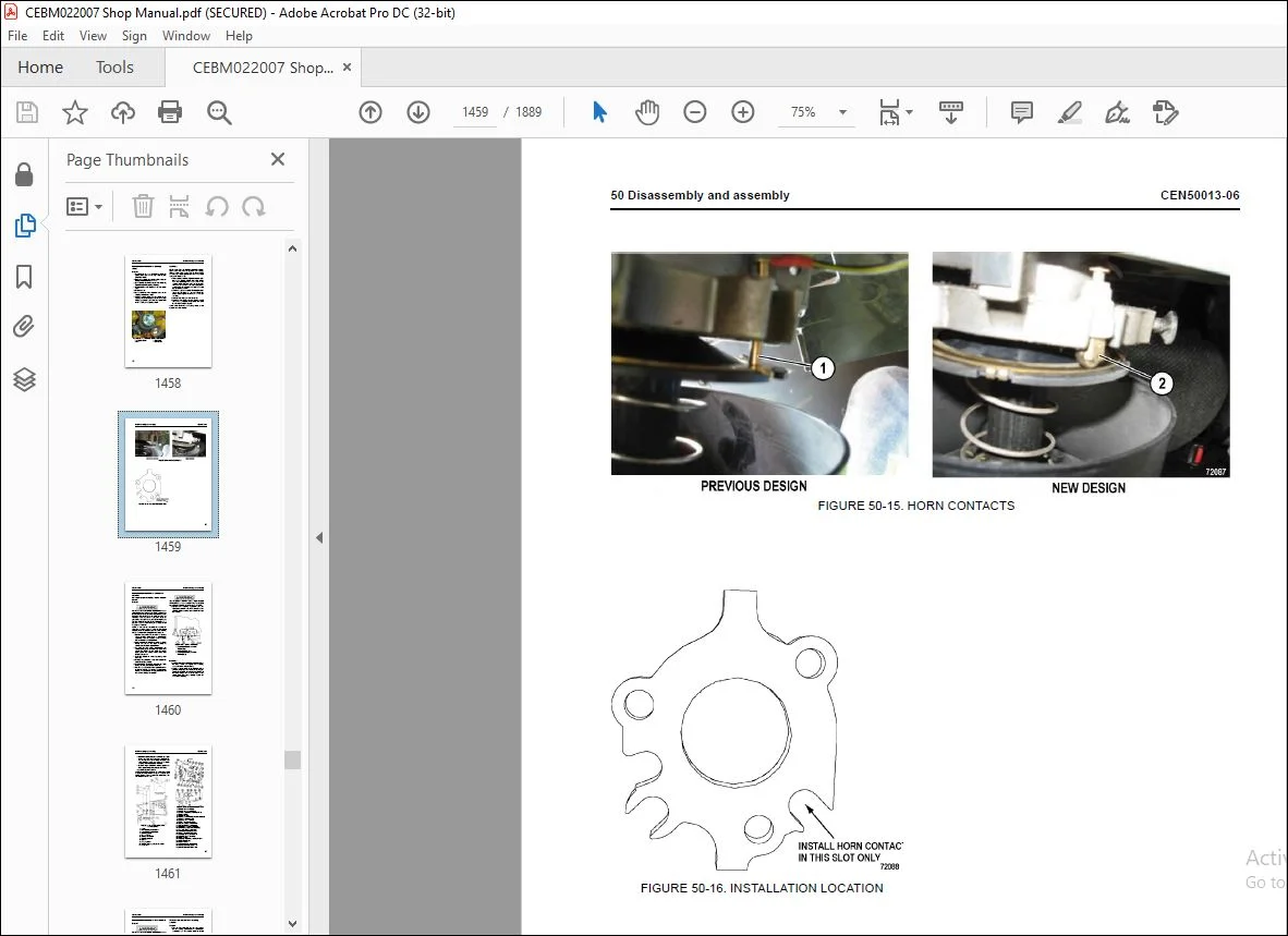
Removal and installation of steering wheel 1458
Removal 1458
Installation 1458
Removal and installation of bleeddown manifold 1460
Removal 1460
Installation 1460
Removal and installation of flow amplifier 1462
Removal 1462
Installation 1462
Removal and installation of steering cylinder 1462
Removal 1462
Bearing replacement 1462
Installation 1463
Disassembly and assembly of steering cylinders 1464
Disassembly 1464
Assembly 1464
Removal and installation of tie rod 1465
Removal 1465
Installation 1466
Removal and installation of steering/brake pump 1466
Removal 1466
Installation 1467
Disassembly and assembly of steering/brake pump 1469
Disassembly 1469
Inspection 1472
Assembly 1475
Driveshaft group 1476
Rotating group 1476
Removal and installation of steering accumulators (piston style) 1479
Removal 1479
Installation 1481
Disassembly and assembly of steering accumulator (piston style) 1481
Cleaning and Inspection 1483
Piston seals replacement 1483
Assembly 1484
Removal and installation of steering accumulators (bladder style) 1485
Removal 1485
Installation 1486
Disassembly and assembly of steering accumulator (bladder style) 1486
Disassembly 1486
Cleaning and Inspection 1487
Assembly 1488
Suspensions 1491
Removal and installation of front suspension 1493
General information 1493
Removal 1493
Installation 1495
Upper mounting joint – 60° advance 1499
Inspection 1500
Minor front suspension repairs (lower bearing and seals) 1501
Lower bearing retainer removal 1501
Lower bearing retainer installation 1501
Major front suspension rebuild 1502
Disassembly 1502
Assembly 1503
Removal and installation of rear suspension 1505
General information 1505
Removal 1505
Installation 1508
Disassembly and assembly of rear suspension 1509
Disassembly 1509
Cleaning and Inspection 1509
Assembly 1510
Hoist circuit 1513
Removal and installation of hoist pump 1515
Removal 1515
Installation 1516
Disassembly and assembly of hoist pump 1518
Disassembly 1518
Inspection 1523
Assembly 1524
Removal and installation of hoist valve 1527
Removal 1527
Installation 1528
Disassembly and assembly of hoist valve 1528
O-ring replacement 1528
Disassembly of inlet section 1530
Assembly of inlet section 1531
Disassembly of rear spool section 1532
Assembly of rear spool section 1534
Disassembly of front spool section 1535
Assembly of front spool section 1536
Overcenter manifold service 1536
Removal and installation of hoist pilot valve 1537
Removal 1537
Installation 1537
Disassembly and assembly of hoist pilot valve 1538
Disassembly 1538
Cleaning and inspection 1539
Assembly 1539
Removal and installation of hoist cylinders 1540
Removal 1540
Installation 1541
Disassembly and assembly of hoist cylinders 1543
Disassembly 1543
Cleaning and inspection 1545
Installation of the quill 1546
Assembly 1548
Replacement of hoist circuit filter 1550
Filter element replacement 1551
Operator cab 1553
Removal and installation of operator cab 1555
Removal 1556
Installation 1557
Removal and installation of cab door 1559
Removal 1559
Installation 1559
Disassembly and assembly of cab door 1559
Removing door panel 1559
Installing door panel 1560
Replacing door window regulator 1560
Replacing door handle or latch assembly 1561
Replacing door assembly seal and door hinge seal 1562
Replacing door opening seal 1562
Removing door glass 1563
Installing door glass 1564
Adjustment of cab door 1566
Door jamb bolt adjustment 1566
Door handle plunger adjustment 1567
Removal and installation of side window glass 1568
Recommended tools and supplies 1568
Removal 1569
Installation 1569
Removal and installation of windshield and rear window glass 1570
Removal 1570
Installation 1570
Removal and installation of windshield wiper motor 1571
Removal 1571
Installation 1571
Removal and installation of windshield wiper arm 1572
Removal 1572
Installation 1572
Removal and installation of windshield wiper linkage 1573
Removal 1573
Installation 1573
Removal and installation of operator seat (standard seat) 1574
Adjustment 1574
Inspection 1575
Removal 1575
Installation 1575
Replacing the Seat Compressor 1576
Removal and installation of passenger seat (standard seat) 1581
Adjustment 1581
Inspection 1582
Removal 1582
Installation 1582
Removal and installation of seat belts (standard seat) 1583
Removal 1583
Installation 1583
Operator seat (optional seat) 1585
Seat Belts 1585
Adjustment 1585
Passenger seat (optional seat) 1586
Seat Belts 1586
Adjustment 1586
Removal and installation of seat belts (optional seat) 1587
General 1587
Removal 1587
Installation 1589
Body and structures 1593
Removal and installation of dump body 1595
Removal 1595
Inspection 1596
Installation 1597
Removal and installation of body pads 1597
Removal 1597
Installation 1598
Adjustment 1598
Removal and installation of diagonal ladder/ hood and grille assembly 1600
Removal 1600
Installation 1600
Removal and installation of right deck 1601
Removal 1601
Installation 1603
Removal and installation of left deck 1604
Removal 1604
Installation 1604
Removal and installation of fuel tank 1606
Removal 1606
Cleaning and inspection 1606
Installation 1608
Removal and installation of horizontally mounted fuel gauge sender 1608
Removal 1608
Installation 1608
Removal and installation of vertically mounted fuel gauge sender 1608
Installation 1608
Disassembly and assembly of fuel tank breather 1610
Disassembly 1610
Assembly 1610
Removal and installation of hydraulic tank 1611
Removal 1611
Installation 1611
Three phase wheel motor 1613
Qualified personnel 1616
General safety information 1616
Handling 1617
Motor 1617
Transport 1618
Storage 1619
Storage of new motors 1619
Storage of used motors 1620
Maintenance 1620
Motor 1620
Safety guidelines 1621
Maintenance intervals 1622
Maintenance work on the installed motor 1622
Checking for external damage 1622
Checking the connections 1623
Regreasing the bearings 1623
Applying grease to the bearings 1623
Checking the interior of the motor for water 1624
Disassembly 1625
Pressing off the coupling 1626
Disassembly 1627
Rotor 1627
Removing the rubber seals and the air baffles 1632
Bearing and labyrinth ring 1633
Removal 1633
Maintenance work 1634
Stator Inspection 1634
Rotor Inspection 1634
Testing the insulation 1635
High-voltage test 1635
Work on the bearings 1636
Assembly 1637
Assembling the rubber seals and the air baffles 1638
Assembly after special repair work 1640
Bearing installation 1641
Preparatory measures for assembling the bearing (Figure 50-20 must be observed): 1644
Assemble the bearing 1645
Cover installation 1646
Assembling the bearing shield (N-end) at the stator frame 1647
Bearing installation 1649
Rotor installation 1651
Labyrinth ring 1653
Installation 1653
Installing accessories (D- and N-end) 1655
Running in the bearings 1659
Coupling 1660
Installation 1660
Assembly conditions and instructions 1661
Tests 1661
Repair work 1662
Replacing defective connecting leads 1662
Repairing the stator winding insulation 1663
Recommended consumables 1663
Chemical cleaning agents 1663
Chemical cleaning agents for outdoor use and for cleaning mechanical parts 1663
Chemical cleaning agents for flange faces 1663
Chemical cleaning agents for windings 1664
Chemical cleaning agents for windings 1664
Chemical cleaning agents for windings with severe damage and for oily windings 1664
Rolling-contact bearing grease 1664
Assembly/disassembly agents for bearing seat 1664
Sealants for joining parts or gaps 1664
Locking agents for connecting elements 1664
Anti-corrosion agent 1664
Assembly paste for temperature sensors 1664
List of tools 1665
Mounting devices for inserting and withdrawing the rotor horizontally 1665
Press for expanding the coupling 1665
Compression devices for pressing on or for support while pressing off 1666
Pulling units with cross beam or disk 1668
Aids 1668
Extraction devices 1669
Repair parts list 1669
Paints for refinishing the painted parts or touching up damaged parts 1669
Power module 1671
Removal and installation of power module 1673
General 1673
Preparation 1673
Removal 1674
Installation 1679
Exhaust tube installation 1681
Exhaust blanket installation 1681
Removal and installation of alternator 1682
Removal 1682
Installation 1684
Engine flywheel adapter face runout 1684
Engine crankshaft endplay 1685
Engine flywheel to flywheel housing adapter – measurement “C” 1685
Alternator housing to rotor – measurement “A” 1686
Measurements after joining the alternator and engine 1688
Flywheel housing face runout 1689
Flywheel housing radial runout 1689
Flywheel/flexplate face runout 1690
Flywheel/flexplate radial runout 1690
Rotor shaft radial runout (assembled) 1691
Joining the alternator and engine 1691
Removal and installation of engine 1693
Removal 1693
Service 1694
Installation 1694
Removal and installation of radiator 1694
Removal 1694
Installation 1696
Repairing the radiator 1698
Internal inspection 1698
External cleaning 1698
Disassembly 1698
Cleaning and inspection 1699
Assembly 1700
Pressure testing 1701
Main blower 1703
Removing the main blower motor 1705
Disassembling the main blower motor 1711
Assembling the main blower motor 1713
Installing the main blower motor 1716
Retarding grid 1723
Removing the grid blower motor 1725
Disassembling the grid blower motor 1727
Assembling the grid blower motor 1729
Installing the grid blower motor 1731
Removing a grid element 1735
Control cabinet 1739
Removing the SIBAC Inverter Module 1741
Required tools/materials 1741
Removal 1744
Installing the SIBAC Inverter Module 1748
Draining and filling the IGBT coolant system 1749
Required tools/materials 1749
Coolant mixture specification (distilled water: Antifrogen® N) 1749
Draining and filling the coolant 1751
Removing and installing the IGBT coolant pump assembly 1754
Required tools/materials 1754
Removal 1755
90 Diagrams and drawings 1759
Hydraulic circuit diagrams 1759
EM1374 1761
EM6298 1762
Electrical circuit diagrams – 24V system 1765
XS6700 1767
HE488 1804
58C-06-00383 1805
Electrical circuit diagrams – drive system 1823
HE486 1825
58C-06-00730 1826
XS3380 1882
Questions? Email us: [email protected]
https://vimeo.com/742187585
DESCRIPTION:
Komatsu 860E-1KT DUMP TRUCK Shop Manual CEBM022007 – PDF DOWNLOAD
SERIAL NUMBERS 860E-1KT A30004 – A30030
ENGINE 16V160
Composition of shop manual:
The contents of this shop manual are shown together with Form No. in a list.
Note 1: Always keep the latest version of this manual in accordance with this list and utilize accordingly.
The marks shown to the right of Form No. denote the following:
: New module (to be filed additionally) : Revision (to be replaced for each Form No.)
Note 2: To file this shop manual in the special binder for management, handle it as follows:
• Place a divider on the top of each section in the file after matching the Tab No. with No. indicated next
to each Section Name shown in the table below:
• File overview and other materials in sections in the order shown below and utilize them accordingly.
PLEASE NOTE:
- This is the SAME MANUAL used by the dealerships to diagnose your vehicle
- No waiting for couriers / posts as this is a PDF manual and you can download it within 2 minutes time once you make the payment.
- Your payment is all safe and the delivery of the manual is INSTANT – You will be taken to the DOWNLOAD PAGE.
- So have no hesitations whatsoever and write to us about any queries you may have : heydownloadss @gmail.com
S.V


