KOMATSU 88E-7 SERIES ENGINE SHOP MANUAL SEN06599-02 – PDF DOWNLOAD
$27.95
KOMATSU 88E-7 SERIES ENGINE SHOP MANUAL SEN06599-02 – PDF DOWNLOAD
Description
KOMATSU 88E-7 SERIES ENGINE SHOP MANUAL SEN06599-02 – PDF DOWNLOAD
FILE DETAILS:
KOMATSU 88E-7 SERIES ENGINE SHOP MANUAL SEN06599-02 – PDF DOWNLOAD
Language : English
Pages : 452
Downloadable : Yes
File Type : PDF
IMAGES PREVIEW OF THE MANUAL:
TABLE OF CONTENTS:
KOMATSU 88E-7 SERIES ENGINE SHOP MANUAL SEN06599-02 – PDF DOWNLOAD
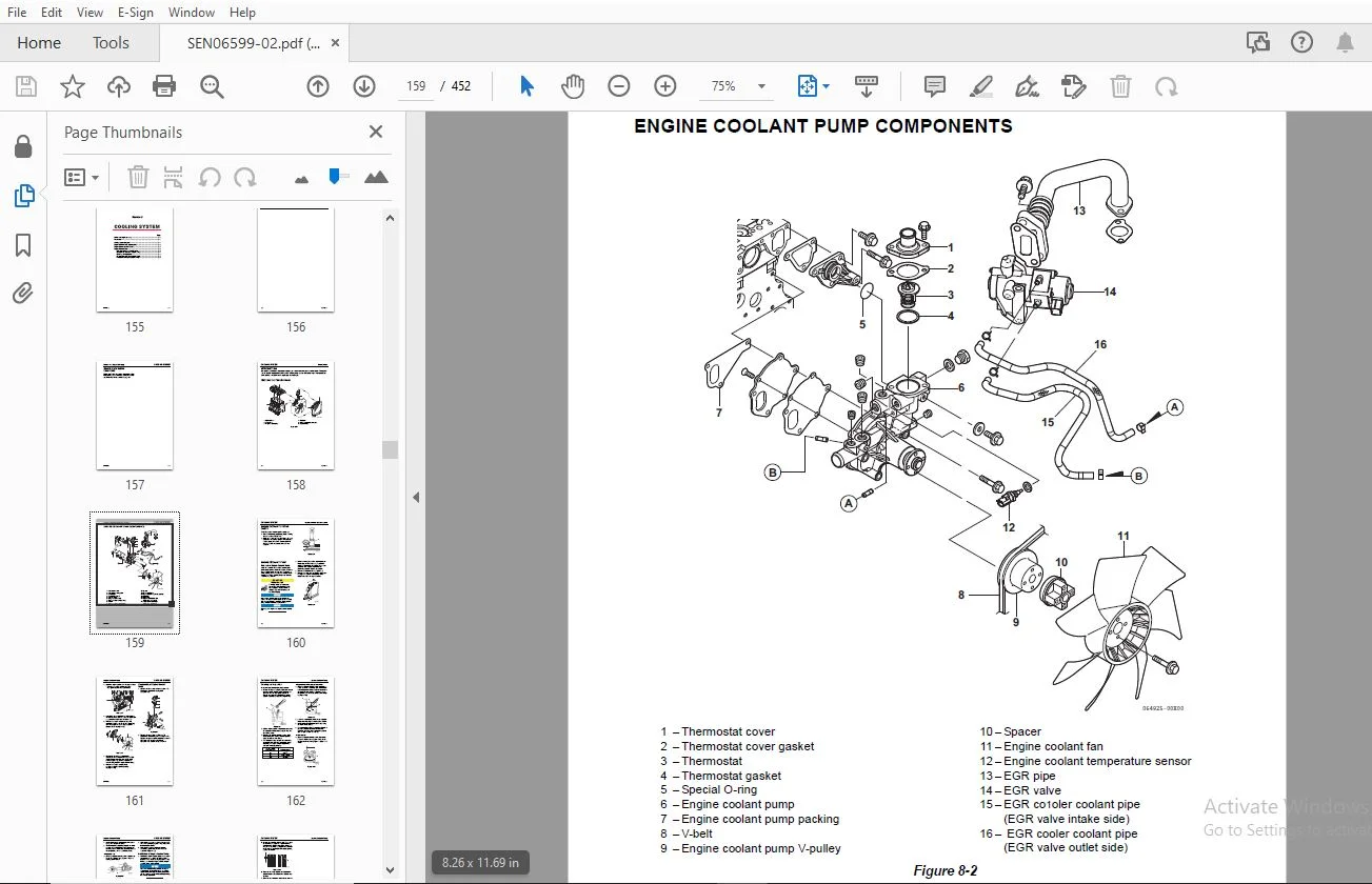
COVER.............................................................................................  3
Table of Contents.................................................................................  3
STRUCTURE AND FUNCTION,TESTING AND ADJUSTING,DISASSEMBLY AND ASSEMBLY,AND MAINTENANCE STANDARD....  5
	Introduction..................................................................................  7
	APPLICABLE MACHINE............................................................................  9
	Safety........................................................................................ 11
		Safety Statements......................................................................... 13
			Precautions for preparatory work...................................................... 13
			Precautions during work............................................................... 13
			Precautions for slinging work and making signals...................................... 14
			Precautions for using mobile crane.................................................... 15
			Precautions for using overhead traveling crane........................................ 16
			Selecting wire ropes.................................................................. 17
			Precautions for disposing of waste materials.......................................... 17
			Drying wiring harness................................................................. 18
			Handling controller................................................................... 19
		Safety Precautions........................................................................ 20
	General Service Information................................................................... 33
		Component Identification.................................................................. 35
		Function of Major Engine Components....................................................... 36
		Function of Cooling System Components..................................................... 37
		Main Electronic Control Components and Features........................................... 38
		Diesel Fuel............................................................................... 40
			Diesel Fuel Specifications............................................................ 40
				Additional technical fuel requirements............................................ 40
				Precautions and concerns regarding the use of diesel fuel......................... 40
				Biodiesel fuels................................................................... 40
				KIT parts list for B 20 (This series engine)...................................... 43
			Filling The Fuel Tank................................................................. 44
			Priming the Fuel System............................................................... 45
		Engine Oil................................................................................ 46
			Engine Oil Specifications............................................................. 46
				Service categories................................................................ 46
				Definitions....................................................................... 46
				Additional technical engine oil requirements:..................................... 46
			Engine Oil Viscosity.................................................................. 46
			Checking Engine Oil................................................................... 47
			Adding Engine Oil..................................................................... 47
			Engine Oil Capacity (Typical)......................................................... 47
		Engine Coolant............................................................................ 48
			Filling Radiator with Engine Coolant.................................................. 49
			Daily Check of the Cooling System..................................................... 49
			Engine Coolant Capacity (Typical)..................................................... 49
		Specifications............................................................................ 50
			Description of Model Number........................................................... 50
			Engine General Specifications......................................................... 50
		Principal Engine Specifications........................................................... 51
		Engine Service Standards.................................................................. 52
		Tightening Torques for Standard Bolts and Nuts............................................ 53
		Abbreviations and Symbols................................................................. 55
			Abbreviations......................................................................... 55
			Symbols............................................................................... 55
		Unit Conversions.......................................................................... 56
			Unit prefixes......................................................................... 56
			Units of length....................................................................... 56
			Units of volume....................................................................... 56
			Units of mass......................................................................... 56
			Units of force........................................................................ 56
			Units of torque....................................................................... 56
			Units of pressure..................................................................... 56
			Units of power........................................................................ 56
			Units of temperature.................................................................. 56
	Periodic Maintenance.......................................................................... 57
		Before You Begin Servicing................................................................ 59
		Introduction.............................................................................. 60
			The Importance of Periodic Maintenance................................................ 60
			Performing Periodic Maintenance....................................................... 60
			Komatsu Replacement Parts............................................................. 60
			Required EPA/ARB Maintenance - USA Only............................................... 60
			EPA/ARB Installation Requirements - USA Only.......................................... 60
		Periodic Maintenance Schedule............................................................. 61
		Periodic Maintenance Procedures........................................................... 62
			Every 1000 Hours of Operation......................................................... 62
				Check and adjust intake/exhaust valve clearance................................... 62
			Every 1500 Hours of Operation......................................................... 62
				Inspect and clean the fuel injection valve........................................ 62
				Inspect crankcase breather system................................................. 62
			Every 3000 Hours of Operation......................................................... 63
				Inspect, clean and test EGR valve................................................. 63
	Engine........................................................................................ 65
		Before You Begin Servicing................................................................ 67
		Introduction.............................................................................. 68
		Cylinder Head Specifications.............................................................. 68
			Adjustment Specifications............................................................. 68
			Cylinder Head......................................................................... 68
			Intake/Exhaust Valve and Guide........................................................ 68
			Push Rod.............................................................................. 69
			Rocker Arm and Shaft.................................................................. 69
			Valve Spring.......................................................................... 69
		Camshaft and Timing Gear Train Specifications............................................. 70
			Camshaft.............................................................................. 70
			Idler Gear Shaft and Bushing.......................................................... 70
			Timing Gear Backlash.................................................................. 70
		Crankshaft and Piston Specifications...................................................... 71
			Crankshaft............................................................................ 71
			Thrust Bearing........................................................................ 71
			Piston................................................................................ 71
			Piston Ring........................................................................... 72
			Connecting Rod........................................................................ 72
				Connecting rod small end.......................................................... 72
				Connecting rod big end............................................................ 72
			Tappet................................................................................ 73
		Cylinder Block Specifications............................................................. 73
			Cylinder Block........................................................................ 73
		Special Torque Chart...................................................................... 74
			Torque for Bolts and Nuts............................................................. 74
		Special Service Tools..................................................................... 75
		Measuring Instruments..................................................................... 77
		Cylinder Head............................................................................. 79
			Cylinder Head Components.............................................................. 79
			Disassembly of Cylinder Head.......................................................... 80
				Removal of cylinder head components............................................... 80
				Removing the glow plugs........................................................... 81
				Removal of rocker arm assembly.................................................... 82
				Disassembly of rocker arm assembly................................................ 82
				Removal of cylinder head.......................................................... 83
				Removal of intake/exhaust valves.................................................. 83
				Removal of valve guides........................................................... 84
			Cleaning of Cylinder Head Components.................................................. 84
			Inspection of Cylinder Head Components................................................ 84
				Inspection of push rods........................................................... 84
					Push rod bend................................................................. 84
				Inspection of rocker arm assembly................................................. 85
					Rocker arm shaft hole diameter................................................ 85
					Rocker arm shaft outside diameter............................................. 85
				Inspection of valve guides........................................................ 85
				Inspection of cylinder head....................................................... 85
					Cylinder head distortion...................................................... 85
				Inspection of intake and exhaust valves........................................... 86
					Valve stem diameter........................................................... 86
					Valve stem bend............................................................... 86
					Valve recession............................................................... 86
					Grinding and lapping the valve seats.......................................... 87
				Inspection of valve springs....................................................... 88
					Fractures..................................................................... 88
					Corrosion..................................................................... 88
					Squareness.................................................................... 88
					Free length................................................................... 88
			Reassembly of Cylinder Head........................................................... 88
				Reassembly of valve guides........................................................ 88
				Reassembly of intake and exhaust valves........................................... 89
				Reassembly of cylinder head....................................................... 90
				Reassembly of rocker arm reassembly............................................... 90
				Attaching the glow plug........................................................... 91
				Attaching the fuel injection valve and the high pressure line..................... 91
				Attaching the parts around the cylinder head...................................... 91
		Measuring and Adjusting Valve Clearance................................................... 92
			3-cylinder engines.................................................................... 92
		Crankshaft and Camshaft................................................................... 94
			Crankshaft and Camshaft Components.................................................... 94
			Disassembly of Engine................................................................. 95
			Disassembly of Camshaft and Timing Components......................................... 96
				Removal of gear case cover........................................................ 96
				Checking timing gear backlash..................................................... 96
				Measuring idler gear-to-crankshaft gear backlash.................................. 96
				Measuring idler gear-to-camshaft gear backlash.................................... 97
				Removal of timing gears........................................................... 97
				Removal of oil pan................................................................ 97
				Removal of camshaft............................................................... 98
				Removal of gear case flange....................................................... 99
			Disassembly of Crankshaft and Piston Components.......................................100
				Removal of pistons................................................................100
				Removal of crankshaft.............................................................101
			Inspection of Crankshaft and Camshaft Components......................................103
				Replacement of crankshaft oil seals...............................................103
				Measure crankshaft bearing oil clearance..........................................104
				Inspection of cylinder block......................................................104
				Inspection of pistons, piston rings and wrist pin.................................104
				Inspection of connecting rod......................................................106
				Inspection of tappets.............................................................106
				Inspection of crankshaft..........................................................107
				Inspection of camshaft............................................................108
				Inspection of camshaft bushing and bores..........................................108
				Inspection of idler gear and shaft................................................108
			Honing and Boring.....................................................................109
			Reassembly of Crankshaft and Piston Components........................................110
				Reassembly of pistons.............................................................110
				Installation of crankshaft........................................................113
				Installation of pistons...........................................................114
			Reassembly of Camshaft and Timing Components..........................................115
				Installation of gear case flange..................................................115
				Installation of camshaft..........................................................116
				Installation of timing gears......................................................116
				Installation of gear case cover...................................................117
				Installation of oil pan...........................................................117
			Final Reassembly of Engine............................................................118
		EGR system................................................................................119
			EGR System............................................................................119
			Disassembly of EGR System.............................................................120
			Inspecting/Cleaning EGR Related Components............................................121
				EGR valve.........................................................................121
				EGR valve operation checks........................................................121
				Cleaning the EGR valves...........................................................122
				EGR active control................................................................122
				Exit the EGR active control.......................................................123
				Precautions for cleaning..........................................................123
				EGR pipe and other connecting elbows..............................................123
				Installing EGR related components/parts...........................................123
	Fuel System...................................................................................125
		Before You Begin Servicing................................................................127
			Cold start device.....................................................................128
			Trochoid Fuel Pump....................................................................128
			Electronically Controlled Governor....................................................128
		Fuel System Specifications................................................................129
			Special Torque Chart..................................................................129
			Test and Adjustment Specifications....................................................130
		Special Service Tools.....................................................................131
		Measuring Instruments.....................................................................131
		Fuel System Diagram.......................................................................132
		Fuel System Components....................................................................133
		Fuel Injection Pump.......................................................................134
			Removal of Fuel Injection Pump........................................................134
			Installation of Fuel Injection Pump...................................................138
				For electronically controlled engine..............................................138
		Checking and Adjusting Fuel Injection Timing..............................................143
			Determining the Fuel Injection Timing Specification...................................143
			Checking Fuel Injection Timing........................................................144
			Adjusting Fuel Injection Timing.......................................................146
		Fuel Injectors............................................................................148
			Removal of Fuel Injectors.............................................................148
			Testing of Fuel Injectors.............................................................149
			Disassembly and Inspection of Fuel Injectors..........................................151
			Adjusting Fuel Injector Pressure......................................................152
			Reassembly of Fuel Injectors..........................................................152
			Installation of the Fuel Injectors....................................................153
	Cooling System................................................................................155
		Before You Begin Servicing................................................................157
		Introduction..............................................................................158
		Cooling System Diagram....................................................................158
		Engine Coolant Pump Components............................................................159
		Engine Coolant System Check...............................................................160
		Engine Coolant Pump.......................................................................160
			Removal of Engine Coolant Pump........................................................160
			Disassembly of Engine Coolant Pump....................................................161
			Cleaning and Inspection...............................................................162
				Engine coolant temperature sensor.................................................162
				Engine coolant temperature switch.................................................162
				Thermostat........................................................................162
				Radiator cap......................................................................163
			Reassembly of Engine Coolant Pump.....................................................163
			Installation of Engine Coolant Pump...................................................163
	Lubrication System............................................................................165
		Before You Begin Servicing................................................................167
		Introduction..............................................................................168
		Oil Pump Service Information..............................................................168
			Engine oil pressure...................................................................168
			Rotor shaft clearance.................................................................168
		Lubrication System Diagram................................................................169
		Checking Engine Oil Pressure..............................................................170
		Trochoid Oil Pump.........................................................................170
			Oil Pump Components...................................................................170
			Disassembly of Oil Pump...............................................................171
			Cleaning and Inspection...............................................................172
				Check outer rotor outside clearance...............................................172
				Outer rotor to inner rotor tip clearance..........................................172
				Check outer rotor side clearance..................................................172
				Check rotor shaft clearance.......................................................173
			Reassembly of Oil Pump................................................................173
	Starter Motor.................................................................................175
		Before You Begin Servicing................................................................177
		Introduction..............................................................................178
		Starter Motor Information.................................................................178
			Standard and Optional.................................................................178
		Starter Motor Specifications..............................................................179
		Starter Motor Troubleshooting.............................................................180
		Starter Motor Components..................................................................181
		Starter Motor.............................................................................182
			Removal of Starter Motor..............................................................182
			Disassembly of Starter Motor..........................................................182
			Inspection and Maintenance............................................................185
			Reassembly............................................................................191
			No-load Test..........................................................................192
			Installation of Starter Motor.........................................................192
	Alternator....................................................................................193
		Before You Begin Servicing................................................................195
		Introduction..............................................................................196
		Alternator Information....................................................................196
			Standard and Optional Alternators.....................................................196
		Alternator Specifications.................................................................196
		Alternator Troubleshooting................................................................197
		Alternator Components.....................................................................198
		Alternator Wiring Diagram.................................................................199
		Alternator Standard Output................................................................200
		Alternator................................................................................201
			Removal of Alternator.................................................................201
			Disassembly of Alternator.............................................................201
			Reassembly of Alternator..............................................................203
			Installation of Alternator............................................................205
	ELECTRONIC CONTROL SYSTEM.....................................................................207
		Before You Begin Servicing................................................................209
		Introduction..............................................................................209
		Electronic Control System.................................................................210
		Troubleshooting of Electronic Control System..............................................211
			Fault Detection Capability............................................................211
			SMARTASSIST-DIRECT (SA-D).............................................................213
	Electric Wiring...............................................................................215
		Electric Wiring Precautions...............................................................217
		Electrical Wire Resistance................................................................218
		Battery Cable Resistance..................................................................219
		Electrical Wire Sizes - Voltage Drop......................................................220
		Conversion of AWG to European Standards...................................................221
TROUBLESHOOTING...................................................................................223
	FAILURE CODE (DTC) GENERAL DESCRIPTION........................................................225
		Failure code (DTC) list...................................................................228
		Description Items.........................................................................231
		Analog Input Related Failures.............................................................232
			Rack position sensor..................................................................232
				(1) #B1202: Failure with Rack Position Sensor (Low Voltage).......................232
				(2) #B1203: Rack Position Sensor Error (High Voltage).............................234
			Accelerator sensor....................................................................236
				(1) #B0122: Accelerator Sensor 1 (Low Voltage)....................................236
				(2) #B0123: Accelerator Sensor 1 (High Voltage)...................................238
				(3) #B0124: Accelerator Sensor 1 Intermittent Failure.............................240
				(4) #B1125: —.....................................................................242
				(5) #B1126: —.....................................................................244
			Spare accelerator sensor (option).....................................................246
				(1) #B0222: —.....................................................................246
				(2) #B0223: —.....................................................................248
				(3) #B0224: —.....................................................................250
				(4) #B1225: —.....................................................................252
				(5) #B1226: —.....................................................................254
				(6) #B1227: —.....................................................................256
			Atmospheric pressure sensor (option)..................................................258
				(1) #B2228: —.....................................................................258
				(2) #B2229: —.....................................................................260
				(3) #B2230: —.....................................................................262
			ECU Temperature Sensor................................................................264
				(1) #B0668: ECU Temperature Sensor Error (Low Voltage)............................264
				(2) #B0669: ECU Temperature Sensor Error (High Voltage)...........................265
				(3) #B1664: ECU Temperature Sensor Intermittent Failure...........................266
				(4) #B0634: ECU Temperature Rise Alarm............................................267
			Cooling water temperature sensor......................................................269
				(1) #B0117: Cooling Water Temperature Sensor Error (Low Volt).....................269
				(2) #B0118: Cooling Water Temperature Sensor Error (High Volt)....................271
				(3) #B0119: Cooling Water Temp Sensor Intermittent Failure........................273
				(4) #B0217: —.....................................................................275
			SENSOR 5V.............................................................................277
				(1) #B0642: 5V Sensor Power Voltage Error (Low Voltage)...........................277
				(2) #B0643: 5V Sensor Power Voltage Error (High Voltage)..........................278
				(3) #B1644: 5V Sensor Power Voltage Intermittent Failure..........................279
			Power supply Voltage..................................................................280
				(1) #B0562: Power Supply Voltage Error (Low Voltage)..............................280
				(2) #B0563: Power Supply Voltage Error (High Voltage).............................282
		Pulse Sensor Related Failures.............................................................284
			Speed Sensor..........................................................................284
				(1) #B0340: Speed Sensor Error....................................................284
			Spare speed sensor (option)...........................................................286
				(1) #B1340: —.....................................................................286
			Engine rotational speed...............................................................288
				(1) #B0219: Overspeed.............................................................288
		Contact Output Related Failures...........................................................290
			Rack actuator Relay...................................................................290
				(1) #B1222: Rack Actuator Relay Abnormality A.....................................290
				DTC Detecting Conditions..........................................................290
				Movement at Error occurrence......................................................290
				Estimation of Failure cause/Error condition.......................................290
				Diagnosis Description.............................................................291
				(2) #B1223: Rack Actuator Relay Abnormality B.....................................292
				DTC Detecting Conditions..........................................................292
				Movement at Error occurrence......................................................292
				Estimation of Failure cause/Error condition.......................................292
				Diagnosis Description.............................................................293
				(3) #B1224: Rack Actuator Relay Intermittent Failure..............................294
				DTC Detecting Conditions..........................................................294
				Movement at Error occurrence......................................................294
				Estimation of Failure cause/Error condition.......................................294
				Diagnosis Description.............................................................295
			Start Assist Relay....................................................................296
				(1) #B1232: Start Assist Relay Abnormality A......................................296
				DTC Detecting Conditions..........................................................296
				Movement at Error occurrence......................................................296
				Estimation of Failure cause/Error condition.......................................296
				Diagnosis Description.............................................................297
				(2) #B1233: Start Assist Relay Abnormality B......................................298
				DTC Detecting Conditions..........................................................298
				Movement at Error occurrence......................................................298
				Estimation of Failure cause/Error condition.......................................298
				Diagnosis Description.............................................................299
				(3) #B1234: Start Assist Relay Intermittent Failure...............................300
				DTC Detecting Conditions..........................................................300
				Movement at Error occurrence......................................................300
				Estimation of Failure cause/Error condition.......................................300
				Diagnosis Description.............................................................301
			CSD solenoid valve....................................................................302
				(1) #B1242: CSD solenoid valve Abnormality A......................................302
				DTC Detecting Conditions..........................................................302
				Movement at Error occurrence......................................................302
				Estimation of Failure cause/Error condition.......................................302
				Diagnosis Description.............................................................303
				(2) #B1243: CSD solenoid valve Abnormality B......................................304
				DTC Detecting Conditions..........................................................304
				Movement at Error occurrence......................................................304
				Estimation of Failure cause/Error condition.......................................304
				Diagnosis Description.............................................................305
				(3) #B1244: CSD solenoid valve Intermittent Failure...............................306
				DTC Detecting Conditions..........................................................306
				Movement at Error occurrence......................................................306
				Estimation of Failure cause/Error condition.......................................306
				Diagnosis Description.............................................................307
			EGR valve.............................................................................308
				(1) #B1402: EGR Valve (Step Motor A-phase) Abnormality A..........................308
				DTC Detecting Conditions..........................................................308
				Movement at Error occurrence......................................................308
				Estimation of Failure cause/Error condition.......................................308
				Diagnosis Description.............................................................309
				(2) #B1403: EGR Valve (Step Motor A-phase) Abnormality B..........................310
				DTC Detecting Conditions..........................................................310
				Movement at Error occurrence......................................................310
				Estimation of Failure cause/Error condition.......................................310
				Diagnosis Description.............................................................311
				(3) #B1412: EGR Valve (Step Motor B-phase) Abnormality A..........................312
				DTC Detecting Conditions..........................................................312
				Movement at Error occurrence......................................................312
				Estimation of Failure cause/Error condition.......................................312
				Diagnosis Description.............................................................313
				(4) #B1413: EGR Valve (Step Motor B-phase) Abnormality B..........................314
				DTC Detecting Conditions..........................................................314
				Movement at Error occurrence......................................................314
				Estimation of Failure cause/Error condition.......................................314
				Diagnosis Description.............................................................315
				(5) #B1422: EGR Valve (Step Motor C-phase) Abnormality A..........................316
				DTC Detecting Conditions..........................................................316
				Movement at Error occurrence......................................................316
				Estimation of Failure cause/Error condition.......................................316
				Diagnosis Description.............................................................317
				(6) #B1423: EGR Valve (Step Motor C-phase) Abnormality B..........................318
				DTC Detecting Conditions..........................................................318
				Movement at Error occurrence......................................................318
				Estimation of Failure cause/Error condition.......................................318
				Diagnosis Description.............................................................319
				(7) #B1432: EGR Valve (Step Motor D-phase) Abnormality A..........................320
				DTC Detecting Conditions..........................................................320
				Movement at Error occurrence......................................................320
				Estimation of Failure cause/Error condition.......................................320
				Diagnosis Description.............................................................321
				(8) #B1433: EGR Valve (Step Motor D-phase) Abnormality B..........................322
				DTC Detecting Conditions..........................................................322
				Movement at Error occurrence......................................................322
				Estimation of Failure cause/Error condition.......................................322
				Diagnosis Description.............................................................323
		Contact Input Related Failures............................................................324
			Oil Pressure Related Failures.........................................................324
				(1) #B1192: Oil Pressure Switch Open Circuit......................................324
				(2) #B1198: Oil Pressure Low Error Alarm..........................................326
			Battery Charge Related Failures.......................................................328
				(1) #B1562: Charge Switch Open Circuit............................................328
				(2) #B1568: Charge Alarm..........................................................330
			Water Temperature Switch..............................................................332
				(1) #B1217: —.....................................................................332
			Air cleaner switch....................................................................334
				(1) #B1101: —.....................................................................334
			Oil-Water Separator Switch............................................................336
				(1) #B1151: —.....................................................................336
		Actuators etc.............................................................................338
			Rack actuator.........................................................................338
				(1) #B1212: Rack Actuator Abnormality (Low Current)...............................338
				(2) #B1213: Rack Actuator Abnormality (High Current)..............................340
				(3) #B1211: Rack Actuator Mechanical Failure......................................342
			Engine................................................................................344
				(1) #B1214: Engine Trouble........................................................344
		E-ECU Internal and Communication Errors...................................................346
			E-ECU Internal Errors.................................................................346
				(1) #B0605: FlashROM Error (Checksum A) ..........................................346
				(2) #B0601: EEPROM Memory Deletion Error .........................................347
				(3) #B0686: Main Relay Error......................................................348
			CAN Communication.....................................................................350
				(1) #BG001: CAN Communication Error...............................................350
			Immobilizer...........................................................................352
				(1) #BG167: Immobilizer CAN Communication Error...................................352
				(2) #BH167: —.....................................................................354
				(3) #BG426: Immobilizer System Error..............................................356
	METHOD AND PROCEDURE OF FAILURE DIAGNOSIS.....................................................357
		Description Items.........................................................................359
			E-ECU Pin Layout Diagram..............................................................360
			How to use the 2G eco-checker harness.................................................361
		Analog Input Related Failures.............................................................362
			Rack position sensor..................................................................362
			Accelerator sensor....................................................................366
			Foot pedal............................................................................370
			Spare Analog (Spare accelerator sensor, Atmospheric pressure sensor)..................374
			Pulse accelerator.....................................................................378
			ECU Temperature Sensor................................................................380
			Cooling water temperature sensor......................................................382
			Sensor 5V.............................................................................386
		Pulse Sensor Related Failures.............................................................390
			Speed Sensor..........................................................................390
			Spare speed sensor....................................................................393
		Contact Output Related Failures...........................................................396
			Rack Actuator Relay...................................................................396
			Start Assist Relay....................................................................400
			CSD Solenoid Valve Coil...............................................................404
			EGR valve.............................................................................408
		Contact Input Related Failures............................................................413
		Actuator Related Failures.................................................................419
			Rack actuator.........................................................................419
		ECU Internal and Communication Errors.....................................................423
			ECU Internal Errors...................................................................423
			Main relay............................................................................425
			CAN Communication.....................................................................429
			Immobilizer...........................................................................431
	Mechanical System Failure Diagnosis...........................................................433
		Special Service Tools.....................................................................435
		Troubleshooting By Measuring Compression Pressure.........................................436
			Compression Pressure Measurement Method...............................................436
		Quick Reference Table For Troubleshooting.................................................440
DESCRIPTION:
KOMATSU 88E-7 SERIES ENGINE SHOP MANUAL SEN06599-02 – PDF DOWNLOAD
Composition of the shop manual
This shop manual contains technical information necessary to perform services in workshops. It is divided into “Structure and Function, Testing and Adjusting, Disassembly and Assembly, and Maintenance Standard” and “Troubleshooting” section for the ease of use.
Basic informaton
This Shop Manual describes the service procedures for 3D88E-7 series direct injection engines. Please use this manual for accurate, quick and safe servicing of the engine. Since the directions in this manual are for a typical engine, some specifications and components may be different from your engine.
Komatsu products are continuously undergoing improvement. This Shop Manual might not address possible field modifications to the equipment. Contact an authorized Komatsu distributor for answers to any questions relating to field modifications.
S.S 25/12/24


