
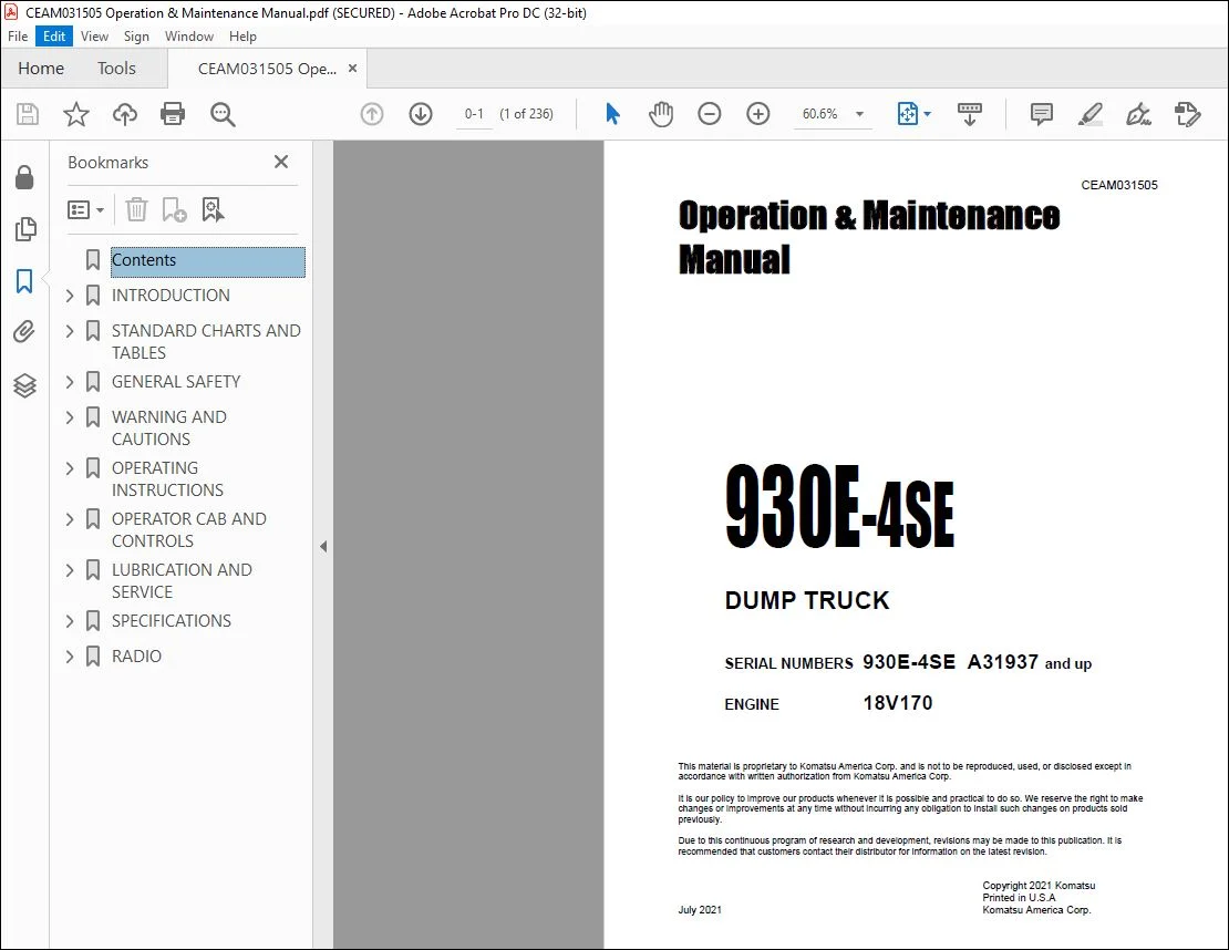
Komatsu 930E-4SE Dump Truck Operation & Maintenance Manual CEAM031505 – PDF DOWNLOAD
Original price was: $86.95.$28.95Current price is: $28.95.
Komatsu 930E-4SE Dump Truck Operation & Maintenance Manual CEAM031505 – PDF DOWNLOAD
Description
Komatsu 930E-4SE Dump Truck Operation & Maintenance Manual CEAM031505 – PDF DOWNLOAD
IMAGES PREVIEW OF THE MANUAL:
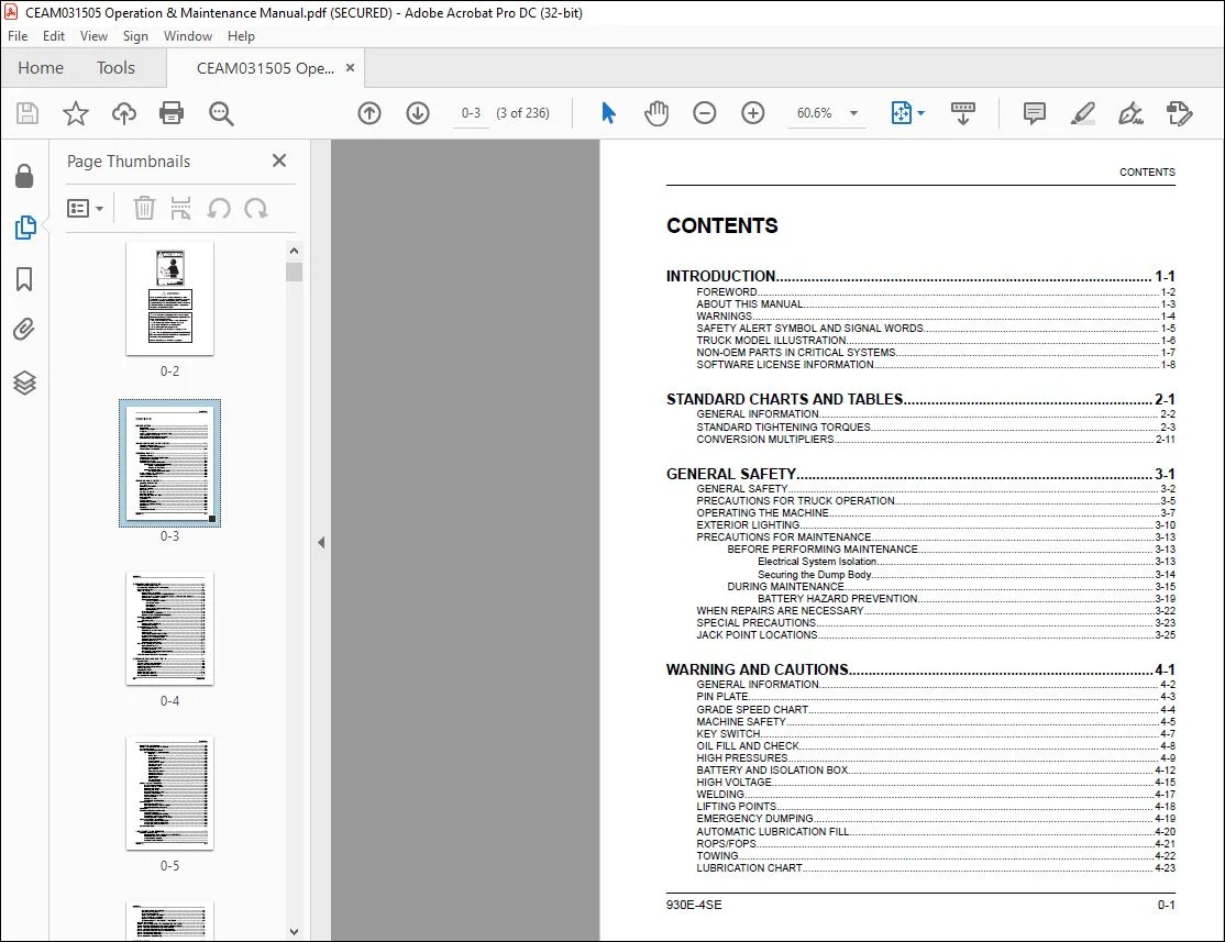
TABLE OF CONTENTS:
Komatsu 930E-4SE Dump Truck Operation & Maintenance Manual CEAM031505 – PDF DOWNLOAD
INTRODUCTION 1-1
FOREWORD 1-2
ABOUT THIS MANUAL 1-3
WARNINGS 1-4
SAFETY ALERT SYMBOL AND SIGNAL WORDS 1-5
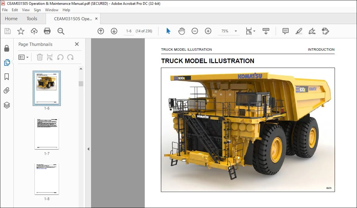
TRUCK MODEL ILLUSTRATION 1-6
NON-OEM PARTS IN CRITICAL SYSTEMS 1-7
SOFTWARE LICENSE INFORMATION 1-8
STANDARD CHARTS AND TABLES 2-1
GENERAL INFORMATION 2-2
STANDARD TIGHTENING TORQUES 2-3
CONVERSION MULTIPLIERS 2-11
GENERAL SAFETY 3-1
GENERAL SAFETY 3-2
PRECAUTIONS FOR TRUCK OPERATION 3-5
OPERATING THE MACHINE 3-7
EXTERIOR LIGHTING 3-10
PRECAUTIONS FOR MAINTENANCE 3-13
BEFORE PERFORMING MAINTENANCE 3-13
Electrical System Isolation 3-13
Securing the Dump Body 3-14
DURING MAINTENANCE 3-15
BATTERY HAZARD PREVENTION 3-19
WHEN REPAIRS ARE NECESSARY 3-22
SPECIAL PRECAUTIONS 3-23
JACK POINT LOCATIONS 3-25
WARNING AND CAUTIONS 4-1
GENERAL INFORMATION 4-2
PIN PLATE 4-3
GRADE SPEED CHART 4-4
MACHINE SAFETY 4-5
KEY SWITCH 4-7
OIL FILL AND CHECK 4-8
HIGH PRESSURES 4-9
BATTERY AND ISOLATION BOX 4-12
HIGH VOLTAGE 4-15
WELDING 4-17
LIFTING POINTS 4-18
EMERGENCY DUMPING 4-19
AUTOMATIC LUBRICATION FILL 4-20
ROPS/FOPS 4-21
TOWING 4-22
LUBRICATION CHART 4-23
CONTENTS
930E-4SE 0-1
OPERATING INSTRUCTIONS 5-1
PREPARING FOR OPERATION 5-2
RETRACTABLE LADDER SYSTEM (If Equipped) 5-7
PRE-SHIFT BRAKE TEST 5-11
TRUCK OPERATION 5-14
ENGINE START-UP SAFETY 5-14
MACHINE OPERATION SAFETY PRECAUTIONS 5-15
SUDDEN LOSS OF ENGINE POWER OR LOSS OF DRIVE SYSTEM FUNCTION 5-20
EMERGENCY STEERING SYSTEM 5-21
KOMVISION (If Equipped) 5-22
KomVision System Precautions 5-22
Component Locations 5-23
Monitor Panel 5-27
Monitor Display 5-28
Radar System Object Detection Range 5-33
Start-Up Inspection 5-37
FUEL DEPLETION 5-38
SAFE PARKING PROCEDURES 5-38
NORMAL ENGINE SHUTDOWN PROCEDURE 5-38
DISABLED TRUCK CONNECTORS 5-40
GENERAL INFORMATION 5-40
HOIST SYSTEM 5-40
TOWING 5-42
SPECIAL WIRING HARNESS 5-43
TOWING PROCEDURE 5-43
PAYLOAD METER IV SYSTEM 5-46
GENERAL INFORMATION 5-46
COMPONENT DESCRIPTION 5-46
SCOREBOARD 5-49
OPERATOR’S DISPLAY AND SWITCH 5-50
PAYLOAD OPERATION & CALCULATION 5-50
SOURCES FOR PAYLOAD ERROR 5-52
DOWNLOADING HAUL CYCLE DATA 5-52
VIEWING ALARM DATA 5-53
DOWNLOADING ALARM DATA 5-54
AUTOMATIC LUBRICATION SYSTEM 5-56
GENERAL INFORMATION 5-56
COMPONENT DESCRIPTION 5-56
SYSTEM OPERATION 5-60
PREVENTIVE MAINTENANCE PROCEDURES 5-61
SYSTEM CHECKOUT 5-62
RESERVE ENGINE OIL SYSTEM (if equipped) 5-64
OPERATOR CAB AND CONTROLS 6-1
CAB INTERIOR 6-3
STEERING WHEEL AND CONTROLS 6-4
PEDALS AND RETARDER LEVER 6-6
OVERHEAD PANEL AND DISPLAYS 6-8
CENTER CONSOLE 6-9
DIAGNOSTIC PORTS 6-12
OPERATOR SEAT (Standard) 6-13
OPERATOR SEAT (Optional) 6-15
PASSENGER SEAT (Standard) 6-17
CONTENTS
0-2 930E-4SE
PASSENGER SEAT (Optional) 6-18
HEATER / AIR CONDITIONER CONTROLS 6-20
INSTRUMENT PANEL 6-21
STATUS INDICATOR LIGHT PANEL 6-26
STATUS INDICATOR LIGHT SYMBOLS 6-26
Body Up 6-26
Parking Brake 6-26
Propel System Not Ready 6-26
No Propel 6-27
Engine Warm Up 6-27
Engine Shutdown Delay 6-27
Retarding Grid Dryer 6-27
Wheel Brake Lock 6-27
Traction Control OFF 6-27
Repair Monitor 6-27
Retractable Ladder Down 6-27
Snapshot In Progress 6-27
Pantograph Energized 6-27
Pantograph Up 6-27
Service Brake 6-28
Dynamic Retarding 6-28
No DC Link Voltage 6-28
DIGITAL DISPLAY OPERATIONS 6-29
DIGITAL DISPLAY MENUS 6-30
ACTIVE WARNINGS MENU 6-31
PAYLOAD DATA MENU 6-31
REPAIR ITEMS MENU 6-32
MAINTENANCE ITEMS MENU 6-32
CLEARED ITEMS MENU 6-33
SYSTEM CONTROLS MENU 6-33
TIRE DATA MENU 6-34
LANGUAGES MENU 6-34
CONFIGURE SYSTEM MENU 6-35
KOMTRAX Plus 6-36
KOMTRAX Plus OPERATION 6-36
DOWNLOADING KOMTRAX Plus DATA 6-37
UPLOADING KOMTRAX Plus DATA 6-39
ORBCOMM 6-41
KOMATSU WIRELESS BRIDGE (KWB) 6-42
VHMS DOWNLOADS 6-42
ONBOARD CONTROLLER ACCESS 6-43
CHANGING A LAPTOP’S IP ADDRESS 6-43
CONNECTING TO A WIRELESS NETWORK 6-44
FUSES AND CIRCUIT BREAKERS 6-46
VEHICLE ELECTRICAL CENTER 89 6-46
VEHICLE ELECTRICAL CENTER 90 6-47
VEHICLE ELECTRICAL CENTER 91 6-49
CIRCUIT BREAKERS 6-53
LUBRICATION AND SERVICE 7-1
GENERAL INFORMATION 7-2
RECOMMENDED FUEL, COOLANT, AND LUBRICANT 7-2
HYDRAULIC SYSTEM SERVICE 7-3
WHEEL MOTOR SERVICE 7-4
COOLANT LEVEL SERVICE 7-4
CONTENTS
930E-4SE 0-3
RESERVE ENGINE OIL SERVICE 7-5
CAB AIR FILTER SERVICE 7-6
FUEL SYSTEM SERVICE 7-7
INTAKE AIR CLEANER SERVICE 7-8
FRONT WHEEL HUB SERVICE 7-9
QUICK FILL SERVICE CENTER 7-9
TIE ROD INSPECTION AND TORQUE PROCEDURE 7-9
LUBRICATION CHART 7-11
INITIAL 50 HOUR LUBRICATION AND MAINTENANCE INSPECTION 7-12
INITIAL 100 HOUR LUBRICATION AND MAINTENANCE INSPECTION 7-13
EVERY 250 HOUR LUBRICATION AND MAINTENANCE 7-14
EVERY 500 HOUR LUBRICATION AND MAINTENANCE 7-17
EVERY 1000 HOURS LUBRICATION AND MAINTENANCE 7-20
EVERY 4000 HOUR MAINTENANCE 7-21
EVERY 5000 HOUR MAINTENANCE 7-22
EVERY 18000 HOUR MAINTENANCE 7-23
SPECIFICATIONS 8-1
MAJOR COMPONENT DESCRIPTION 8-2
Truck and Engine 8-2
Traction Alternator 8-2
Main Control Cabinet 8-2
AC Induction Traction Motorized Wheels 8-2
Suspension 8-2
Operator’s Cab 8-2
Power Steering 8-2
Dynamic Retarding 8-2
Brake System 8-3
SPECIFICATIONS 8-4
Engine 8-4
AC Electric Drive System 8-4
Dynamic Retarding 8-4
Battery Electric System 8-4
Service Capacities 8-4
Hydraulic Systems 8-4
Service Brakes 8-5
Steering 8-5
Standard Dump Body Capacities and Dimensions 8-5
Tires 8-5
Weight Distribution 8-5
Overall Truck Dimensions 8-5
RADIO 9-1
AM/FM RADIO / CD / MP3 / USB / iPOD™ / AUX PLAYER 9-3
Phone/Bluetooth Button 9-3
Digital Display 9-3
CD Slot 9-3
Volume Knob/OK Button 9-3
SRC/PWR (Source/Power) Button 9-4
NEXT Button 9-4
Eject Button 9-4
USB Connection Port 9-4
Auxiliary Jack Port 9-4
SCAN/ASCN (Scan/Autoscan) Button 9-5
CONTENTS
0-4 930E-4SE
PREV (Previous) Button 9-5
DISP (Display) Button 9-5
ESC (Escape) Button 9-5
RDM (Random) Button 9-5
RPT (Repeat) Button 9-5
Clock/Alarm Button 9-5
Adjusting the Clock 9-5
Browse Button 9-6
Play/Pause Button 9-6
Preset Buttons 9-6
Storing Radio Station Presets 9-6
CONTENTS
Need help? Contact: [email protected]
https://vimeo.com/742189896
DESCRIPTION:
Komatsu 930E-4SE Dump Truck Operation & Maintenance Manual CEAM031505 – PDF DOWNLOAD
SERIAL NUMBERS 930E-4SE A31937 and up
ENGINE 18V170
FOREWORD:
- This manual is written for use by the operator and/or the service technician and is designed to help these
persons become fully knowledgeable of the truck and all its systems in order to keep it operating safely and
efficiently. - All operators and maintenance personnel must read and understand the materials in this manual before
operating the truck or performing maintenance and/or operational checks on the truck. All safety notices,
warnings and cautions are to be understood and followed when operating or accomplishing repairs on the truck. - The illustrations used in this manual are typical of the component shown and may not be an exact reproduction
of what is found on the truck. - A product identification plate is located on the frame in front of the right side front wheel and designates the
truck model number, product identification number (vehicle serial number), and maximum GVW (Gross Vehicle
Weight) rating. - The KOMATSU truck model designation consists of three numbers and one letter (i.e. 830E).
- The three numbers represent the basic truck model.
- The letter “M”, when present, designates a Mechanical drive system;
- The letter “E”, when present, designates an Electrical wheel motor drive system.
The product identification number (vehicle serial number) contains information which will identify the original
manufacturing bill of material for this unit. This complete number will be necessary for proper ordering of many
service parts and/or warranty consideration. - The GVW is what determines the load on the drive train, frame, tires, and other components. The vehicle design
and application guidelines are sensitive to the total maximum GVW. GVW is TOTAL WEIGHT: the Empty Vehicle
Weight + the fuel & lubricants + the payload. - To determine allowable payload: Service all lubricants for proper level and fill fuel tank of empty truck (which
includes all accessories, body liners, tailgates, etc.) and then weigh truck. Record this value and subtract from
the GVW rating. The result is the allowable payload.
PLEASE NOTE:
- This is not a physical manual but a digital manual – meaning no physical copy will be couriered to you. The manual can be yours in the next 2 mins as once you make the payment, you will be directed to the download page IMMEDIATELY.
- This is the same manual used by the dealers inorder to diagnose your vehicle of its faults.
- Require some other service manual or have any queries: please WRITE to us at [email protected]
S.V



