
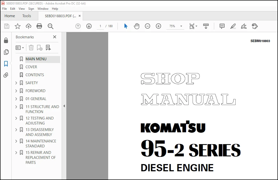
Komatsu 95-2 Series Diesel Engine Shop Manual SEBM018803 – PDF DOWNLOAD
Original price was: $78.95.$28.95Current price is: $28.95.
Komatsu 95-2 Series Diesel Engine Shop Manual SEBM018803 – PDF DOWNLOAD
Description
Komatsu 95-2 Series Diesel Engine Shop Manual SEBM018803 – PDF DOWNLOAD
FILE DETAILS:
Komatsu 95-2 Series Diesel Engine Shop Manual SEBM018803 – PDF DOWNLOAD
Language : English
Pages : 180
Downloadable : Yes
File Type : PDF
Size: 9.04 MB
IMAGES PREVIEW OF THE MANUAL:
DESCRIPTION:
Komatsu 95-2 Series Diesel Engine Shop Manual SEBM018803 – PDF DOWNLOAD
The Komatsu 95-2 Series Diesel Engine Shop Manual SEBM018803 is a technical manual that provides comprehensive information and instructions for the maintenance, repair, and overhaul of several Komatsu diesel engines. These engines are commonly used in Komatsu construction equipment, including excavators, bulldozers, and wheel loaders.
- The manual is organized into several sections, each of which covers different aspects of engine maintenance and repair. The sections include general specifications, testing and adjusting procedures, disassembly and assembly instructions, and troubleshooting guidelines.
- The general specifications section provides an overview of the engine’s technical specifications, including its dimensions, weight, power output, and torque ratings. It also includes information on the engine’s various components, such as the cylinder block, cylinder head, crankshaft, and pistons.
- The testing and adjusting procedures section of the manual provides step-by-step instructions for performing various tests and adjustments on the engine. These procedures include compression tests, fuel injection timing adjustment, and valve clearance adjustment. The manual also provides information on the tools and equipment required for performing these procedures.
- The disassembly and assembly instructions section of the manual provides detailed guidance on how to disassemble and reassemble the engine, including the removal and installation of various components such as the cylinder head, pistons, and crankshaft. This section also includes detailed diagrams and illustrations that provide a clear understanding of the engine’s internal components and how they fit together.
- The troubleshooting guidelines section of the manual provides information on how to diagnose and repair common problems that may occur with the engine. This section provides a list of potential symptoms and causes, along with step-by-step instructions for identifying and fixing the problem.
- Overall, the Komatsu 95-2 Series Diesel Engine Shop Manual SEBM018803 is an essential resource for technicians and mechanics working with the Komatsu 95-2 series engines. Its comprehensive coverage of maintenance, repair, and troubleshooting procedures make it an indispensable tool for ensuring the reliable and efficient operation of Komatsu construction equipment.
TABLE OF CONTENTS:
Komatsu 95-2 Series Diesel Engine Shop Manual SEBM018803 – PDF DOWNLOAD
MAIN MENU……………………………………………………………………………… 0
COVER…………………………………………………………………………………. 1
CONTENTS………………………………………………………………………………. 2
SAFETY………………………………………………………………………………… 5
SAFETY NOTICE………………………………………………………………………. 5
FOREWORD………………………………………………………………………………. 7
GENERAL……………………………………………………………………………. 7
HOW TO READ THE SHOP MANUAL………………………………………………………….. 8
HOISTING INSTRUCTIONS……………………………………………………………….. 9
METHOD OF DISASSEMBLING, CONNECTING PUSH-PULL TYPE COUPLER………………………………. 10
COATING MATERIALS…………………………………………………………………… 12
STANDARD TIGHTENING TORQUE…………………………………………………………… 14
ELECTRIC WIRE CODE………………………………………………………………….. 17
CONVERSION TABLE……………………………………………………………………. 18
UNITS……………………………………………………………………………… 24
01 GENERAL…………………………………………………………………………….. 25
APPLICABLE MACHINE………………………………………………………………….. 26
SPECIFICATIONS……………………………………………………………………… 27
WEIGHT TABLE……………………………………………………………………….. 29
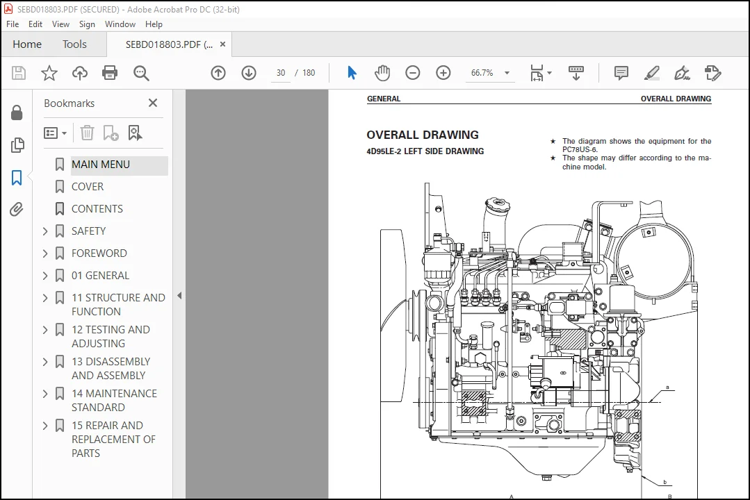
OVERALL DRAWING ……………………………………………………………………. 30
ENGINE PERFORMANCE CURVE…………………………………………………………….. 33
11 STRUCTURE AND FUNCTION……………………………………………………………….. 36
GENERAL STRUCTURE…………………………………………………………………… 37
GENERAL STRUCTURE……………………………………………………………….. 37
INTAKE AND EXHAUST SYSTEM …………………………………………………………… 39
INTAKE AND EXHAUST SYSTEM ……………………………………………………….. 39
AIR CLEANER…………………………………………………………………….. 41
ENGINE BODY………………………………………………………………………… 43
CYLINDER HEAD…………………………………………………………………… 43
CYLINDER BLOCK………………………………………………………………….. 45
MAIN CIRCULATION SYSTEM………………………………………………………….. 47
TIMING GEAR…………………………………………………………………….. 49
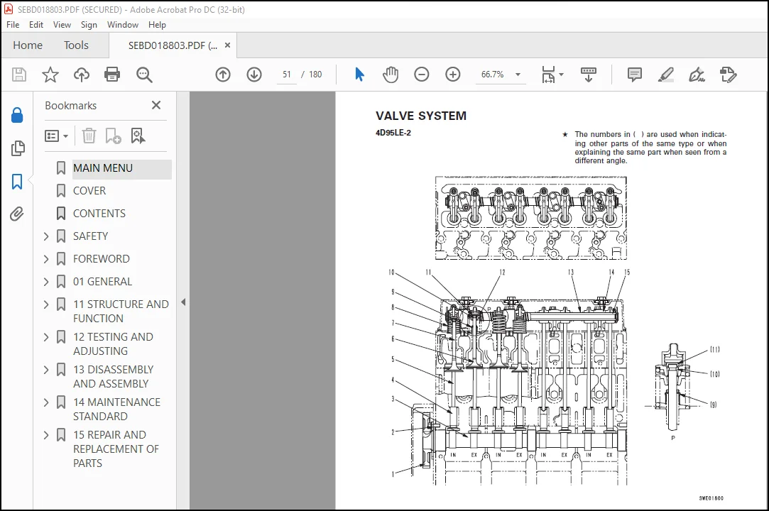
VALVE SYSTEM …………………………………………………………………… 51
FLYWHEEL AND FLYWHEEL HOUSING…………………………………………………….. 53
LUBRICATION SYSTEM …………………………………………………………………. 55
LUBRICATION SYSTEM CHART…………………………………………………………. 55
OIL PUMP……………………………………………………………………….. 56
OIL FILTER …………………………………………………………………….. 57
OIL FILTER MOUNT………………………………………………………………… 58
FUEL SYSTEM ……………………………………………………………………….. 60
FUEL SYSTEM CHART……………………………………………………………….. 60
FUEL INJECTION PUMP……………………………………………………………… 61
FUEL INJECTION NOZZLE……………………………………………………………. 63
FUEL FILTER…………………………………………………………………….. 64
ENGINE CUT SOLENOID……………………………………………………………… 65
COOLING SYSTEM……………………………………………………………………… 66
COOLING SYSTEM CHART…………………………………………………………….. 66
WATER PUMP……………………………………………………………………… 67
FAN DRIVE AND THERMOSTAT…………………………………………………………. 68
ELECTRICAL SYSTEM ………………………………………………………………….. 71
STARTING AND CHARGING SYSTEM ELECTRICAL CIRCUIT DIAGRAM……………………………… 71
ALTERNATOR……………………………………………………………………… 72
STARTING MOTOR………………………………………………………………….. 73
ENGINE STARTING DEVICE…………………………………………………………… 74
12 TESTING AND ADJUSTING………………………………………………………………… 75
TESTING AND ADJUSTING……………………………………………………………….. 76
ADJUSTING VALVLE CLEARANCE……………………………………………………….. 76
MEASURING COMPRESSION PRESSURE……………………………………………………. 78
ADJUSTING FUEL INJECTION PRESSURE…………………………………………………. 79
TESTING AND ADJUSTING FUEL INJECTION TIMING………………………………………… 80
ADJUSTING FUEL CUT SOLENOID………………………………………………………. 84
FUEL INJECTION PUMP CALIBRATION DATA………………………………………………….. 87
PERFORMANCE TEST …………………………………………………………………… 90
RUN-IN STANDARD…………………………………………………………………. 90
PERFORMANCE TEST CRITERIA ……………………………………………………….. 91
TROUBLESHOOTING…………………………………………………………………….. 93
METHOD OF USING TROUBLESHOOTING CHARTS…………………………………………….. 94
POINTS TO REMEMBER WHEN TROUBLESHOOTING……………………………………………. 98
S-1 STARTING PERFORMANCE IS POOR (STARTING ALWAYS TAKES TIME)………………………… 99
S-2 ENGINE DOES NOT START…………………………………………………………100
(1) ENGINE DOES NOT TURN………………………………………………………100
(2) ENGINE TURNS BUT NO EXHAUST SMOKE COMES OUT (FUEL IS NOT BEING INJECTED)………..101
(3) EXHAUST SMOKE COMES OUT, BUT ENGINE DOES NOT START (FUEL IS NOT BEING INJECTED)….102
S-3 ENGINE DOES NOT PICK UP SMOOTHLY……………………………………………….103
S-4 ENGINE STOPS DURING OPERATIONS…………………………………………………104
S-5 ENGINE DOES NOT ROTATE SMOOTHLY (HUNTING)……………………………………….105
S-6 ENGINE LACK OUTPUT (NO POWER)………………………………………………….106
S-7 EXHAUST GAS IS BLACK………………………………………………………….107
S-8 OIL CONSUMPTION IS EXCESSIVE, OR EXHAUST GAS IS BLUE……………………………..108
S-9 OIL BECOMES CONTAMINATED QUICKLY……………………………………………….109
S-10 FUEL CONSUMPTION IS EXCESSIVE…………………………………………………110
S-11 OIL IS IN COOLING WATER ……………………………………………………..111
S-12 OIL PRESSURE CAUTION LAMP LIGHTS UPS (DROP IN OIL PRESSURE)………………………112
S-13 OIL LEVEL RISES (WATER, FUEL IN OIL )………………………………………….113
S-14 WATER TEMPERATURE BECOMES TOO HIGH (OVERHEATING)………………………………..114
S-15 ABNORMAL NOISE IS MADE……………………………………………………….115
S-16 VIBRATION IS EXCESSIVE……………………………………………………….116
TESTING AND ADJUSTING TOOL LIST……………………………………………………….117
TESTING AND ADJUSTING DATA……………………………………………………………118
13 DISASSEMBLY AND ASSEMBLY………………………………………………………………120
SPECIAL TOOL LIST……………………………………………………………………121
OVERALL DISASSEMBLY OF 4D95LC-2……………………………………………………….122
PREPARATORY WORK…………………………………………………………………123
1. ALTERNATOR, FAN PULLEY…………………………………………………………123
2. STARTING MOTOR, ENGINE STOP SOLENOID, FUEL AND OIL FILTERS, DIPSTICK………………..124
3. WATER PUMP……………………………………………………………………124
4. FUEL INJECTION TUBE, GLOW PLUG………………………………………………….124
5. INJECTION NOZZLE………………………………………………………………124
6. FUEL INJECTION PUMP……………………………………………………………125
7. INTAKE MANIFOLD……………………………………………………………….125
8. EXHAUST MANIFOLD………………………………………………………………125
9. HEAD COVER……………………………………………………………………125
10. ROCKER ARM…………………………………………………………………..126
11. PUSH ROD, CYLINDER HEAD MOUNTING BOLT…………………………………………..126
12. CYLINDER HEAD COVER…………………………………………………………..126
13. PTO SHAFT……………………………………………………………………127
14. OIL PAN……………………………………………………………………..128
15. OIL SUCTION PIPE……………………………………………………………..128
16. CRANKSHAFT PULLEY…………………………………………………………….128
17. GEAR CASE COVER………………………………………………………………128
18. OIL PUMP, IDLER GEAR………………………………………………………….129
19. CAMSHAFT ASSEMBLY…………………………………………………………….129
20. FLYWHEEL…………………………………………………………………….129
21. FLYWHEEL HOUSING……………………………………………………………..130
22. PISTION, CONNECTING ROD ASSEMBLY……………………………………………….130
23. MAIN CAP…………………………………………………………………….132
24. CRANKSHAFT…………………………………………………………………..133
25. TAPPET………………………………………………………………………133
26.CYLINDER BLOCK ASSEMBLY………………………………………………………..133
OVERALL ASSEMBLY…………………………………………………………………….134
1. CYLINDER BLOCK ASSEMBLY………………………………………………………..134
2. TAPPET……………………………………………………………………….134
3. CRANKSHAFT……………………………………………………………………134
4. MAIN CAP……………………………………………………………………..135
5. FLYWHEEL HOUSING………………………………………………………………138
6. FLYWHEEL……………………………………………………………………..139
7. CAMSHAFT ASSEMBLY……………………………………………………………..139
8. OIL PUMP, IDLER GEAR…………………………………………………………..140
9. GEAR CASE COVER……………………………………………………………….141
10. CRANKSHAFT PULLEY…………………………………………………………….141
11. OIL SUCTION PIPE……………………………………………………………..141
12. OIL PAN……………………………………………………………………..142
13. PTO SHAFT……………………………………………………………………142
14. FUEL INJECTION PUMP…………………………………………………………..142
15. CYLINDER HEAD ASSEMBLY………………………………………………………..143
16. ADJUSTMENT OF VALVE CLEARANCE………………………………………………….145
17. HEAD COVER…………………………………………………………………..146
18. EXHAUST MANIFOLD……………………………………………………………..146
19. INTAKE MANIFOLD………………………………………………………………146
20. INJECTION NOZZLE……………………………………………………………..146
21. FUEL INJECTION TUBE, GLOW PLUG…………………………………………………147
22. WATER PUMP…………………………………………………………………..147
23. STARTING MOTOR. ENGINE STOP SOLENOID, FUEL AND OIL FILTERS, DIPSTICK……………….147
24. ALTERNATOR, FAN PULLEY………………………………………………………..148
25. ENGINE ASSEMBLY………………………………………………………………148
26. FAN, EXHAUST PIPE, MUFFLER, ENGINE OIL TUBES, BLOCK, COVER………………………..149
14 MAINTENANCE STANDARD………………………………………………………………….150
CYLINDER HEAD……………………………………………………………………….151
VALVE AND VALVE GUIDE………………………………………………………………..152
ROCKER ARM SHAFT, PUSH ROD AND TAPPET………………………………………………….153
CYLINDER BLOCK………………………………………………………………………154
CYLINDER……………………………………………………………………………155
CRANKSHAFT………………………………………………………………………….156
CAMSHAFT……………………………………………………………………………157
TIMING GEAR…………………………………………………………………………158
PISTION, PISTON RING AND PISTION PIN…………………………………………………..159
CONNECTING ROD………………………………………………………………………160
FLYWHEEL AND FLYWHEEL HOUSING…………………………………………………………161
OIL PUMP……………………………………………………………………………162
REGULATOR VALVE……………………………………………………………………..163
WATER PUMP AND THERMOSTAT…………………………………………………………….164
15 REPAIR AND REPLACEMENT OF PARTS………………………………………………………..165
CYLINDER HEAD SECTION………………………………………………………………..166
GRINDING CYLINDER HEAD MOUNTING SURFACE…………………………………………….166
REPLACING VALVE GUIDE…………………………………………………………….167
GRINDING VALVE…………………………………………………………………..168
CYLINDER BLOCK SECTION……………………………………………………………….169
REPLACING CAMSHAFT BUSHING………………………………………………………..169
REPLACING CRANKSHAFT GEAR…………………………………………………………171
REPLACING CAM GEAR……………………………………………………………….172
REPLACING FLYWHEEL RING GEAR………………………………………………………173
PROCEDURE FOR PRESSURE TEST ………………………………………………………174
CYLINDER LINER (SPECIAL RESTORATION PART)…………………………………………..175
MACHINING DRAWING FOR CYLINDER BLOCK BORE…………………………………………..176
ADDITIONAL MACHINING OF CAM JOURNAL………………………………………………..177
GRINDING CRANKSHAFT………………………………………………………………178
REPLACING CONNECTING ROD SMALL END BUSHING………………………………………….179
Customer Support: [email protected]
PLEASE NOTE:
- This is the SAME manual used by the dealers to troubleshoot any faults in your vehicle. This can be yours in 2 minutes after the payment is made.
- Contact us at [email protected] should you have any queries before your purchase or that you need any other service / repair / parts operators manual.
S.V



