Komatsu 960E-2 Dump Truck Shop Manual CEBM025901 – PDF DOWNLOAD
Original price was: $59.95.$33.95Current price is: $33.95.
Komatsu 960E-2 Dump Truck Shop Manual
SERIAL NUMBERS : A30027 & UP
Description
Komatsu 960E-2 Dump Truck Shop Manual
FILE DETAILS:
Komatsu 960E-2 Dump Truck Shop Manual
Brands: Komatsu
Equipment Type: Dump Truck
Manuals Type: Shop Manual
Machine Model: 960E-2
Serial Number: A30027 & UP
Book Code: CEBM025901
Language: English
Pages: 978
File Format: Portable Document Format (PDF)
DESCRIPTION:
Komatsu 960E-2 Dump Truck Shop Manual
How to read the shop manual:
Composition of shop manual:
• This shop manual describes the technical information required for the services performed in a workshop. The shop manual is divided into the following chapters for the convenience of use.
00. Index and foreword:
• This section includes the index, foreword, safety and basic information.
01. Specification:
• This section explains the specifications of the machine.
10. Structure and function:
• This section explains the structure and function of the machine. The section of “Structure and function” serves not only to give an understanding for the structure of each component, but also serves as reference material for troubleshooting.
20. Standard value table:
• The standard values for a new machine and trouble shooting are indicated. This standard value table is used for testing and adjusting, and determining a failure at troubleshooting.
30. Testing and adjusting:
• This section describes the measuring tools and how to measure, and how to adjust various parts. As for the standard value and failure criterion, see the standard value table.
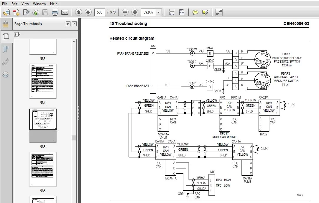
40. Troubleshooting:
• This section describes the troubleshooting in a suspected area when a failure occurs and the remedy for the failure. Troubleshooting is described by each failure mode.
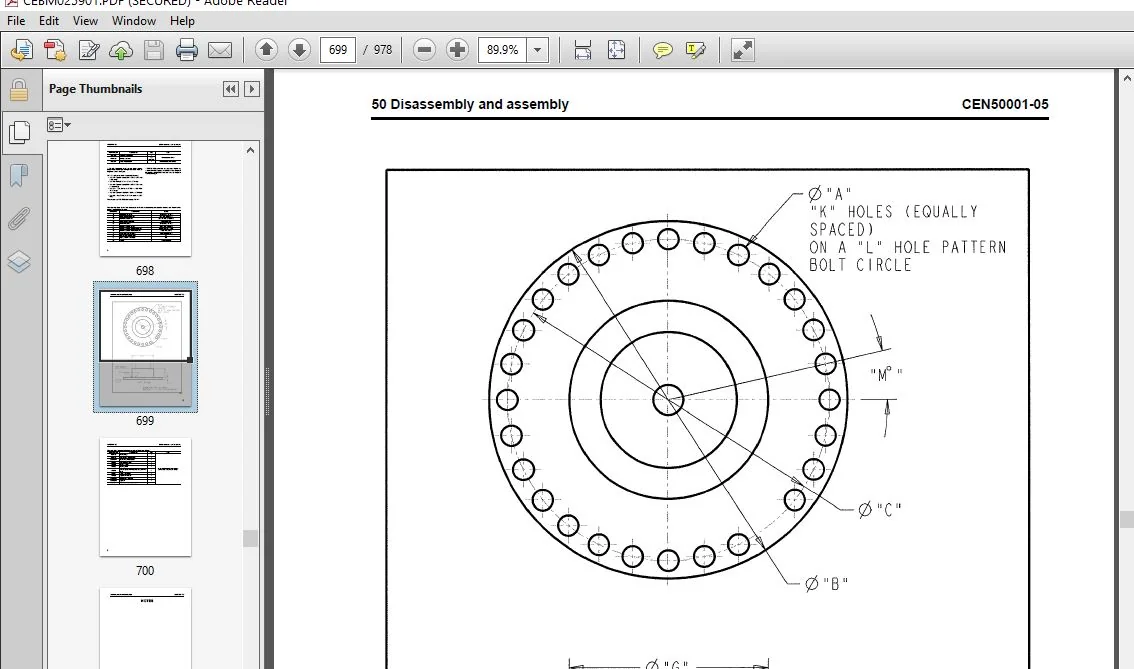
50. Disassembly and assembly:
• This section explains the procedures for removing, installing, disassembling, and assembling each part or component and the special tools for the works as well as precautions for doing them safely. In addition, tightening torque, and quantity and weight of coating material, oil, grease, and coolant required for the works are also explained.
60. Maintenance standard:
• This section describes the maintenance standard values for each component. This section gives the criterion values for each component and required remedy at disassembly or maintenance.
80. Appendix:
• The structure and function, testing and adjusting, and troubleshooting for all of the other components or equipment which can not be separately classified are explained together in the appendix.
90. Diagrams and drawings:
• This section gives hydraulic circuit diagrams and electrical circuit diagrams.
TABLE OF CONTENTS:
Komatsu 960E-2 Dump Truck Shop Manual
Cover.................................................................................................................................  1
00 Index and foreword.................................................................................................................  3
	Index.............................................................................................................................  3
		Composition of shop manual....................................................................................................  4
		Table of contents.............................................................................................................  6
	Foreword, safety and general information.......................................................................................... 17
		Foreword...................................................................................................................... 20
		How to read the shop manual................................................................................................... 21
			Composition of shop manual................................................................................................ 21
			Revision and distribution................................................................................................. 21
			Symbols................................................................................................................... 22
		General safety................................................................................................................ 23
			Safety rules.............................................................................................................. 23
			Safety features........................................................................................................... 23
			Fire extinguisher and first aid kit....................................................................................... 23
			Clothing and personal items............................................................................................... 23
			Leaving the operator seat................................................................................................. 24
			Mounting and dismounting.................................................................................................. 24
			Fire prevention for fuel and oil.......................................................................................... 24
			Precautions with high temperature fluids.................................................................................. 25
			Asbestos dust hazard prevention........................................................................................... 25
			Prevention of injury by work equipment.................................................................................... 25
			Unauthorized modification................................................................................................. 25
			Precautions when using ROPS............................................................................................... 25
			Precautions for attachments............................................................................................... 26
			Precautions for starting the truck........................................................................................ 26
		Precautions before operating the truck........................................................................................ 26
			Safety at the worksite.................................................................................................... 26
			Fire prevention........................................................................................................... 27
			Ventilation in enclosed areas............................................................................................. 27
			Preparing for operation................................................................................................... 27
			Mirrors, windows and lights............................................................................................... 27
			In operator cab (before starting the engine).............................................................................. 27
			Seat Belts................................................................................................................ 27
		Precautions while operating the truck......................................................................................... 28
			When starting the engine.................................................................................................. 28
			General truck operation................................................................................................... 28
			Ensuring good visibility.................................................................................................. 28
			Traveling................................................................................................................. 29
			Traveling in reverse...................................................................................................... 29
			Traveling on slopes....................................................................................................... 29
			Operating on snow or ice.................................................................................................. 29
			Avoid damage to dump body................................................................................................. 29
			Driving near high voltage cables.......................................................................................... 30
			When dumping.............................................................................................................. 30
			When loading.............................................................................................................. 30
			Working on loose ground................................................................................................... 30
			Parking the truck......................................................................................................... 30
			Towing.................................................................................................................... 30
		Working near batteries........................................................................................................ 31
			Battery hazard prevention................................................................................................. 31
			Starting with booster cables.............................................................................................. 32
			Jump starting with receptacles............................................................................................ 32
		Precautions before performing service......................................................................................... 33
			Warning tag............................................................................................................... 33
			Stopping the engine....................................................................................................... 33
			Proper tools.............................................................................................................. 33
			Use of Tie-Off Anchor During Maintenance and Repair....................................................................... 33
			Securing the dump body.................................................................................................... 34
		Precautions while performing service.......................................................................................... 35
			Keep the truck clean...................................................................................................... 35
			Attachments............................................................................................................... 35
			Working under the truck................................................................................................... 35
			Rotating fan and belts.................................................................................................... 35
			Adding fuel or oil........................................................................................................ 35
			Use of lighting........................................................................................................... 35
			Radiator coolant level.................................................................................................... 36
			Precautions with the battery.............................................................................................. 36
			Precautions with high pressure oil........................................................................................ 36
			Handling high pressure hoses.............................................................................................. 36
			Precautions when performing maintenance near high temperature or high pressure............................................ 36
			Waste materials........................................................................................................... 36
		Tires......................................................................................................................... 37
			Handling tires............................................................................................................ 37
			Storing tires after removal............................................................................................... 37
		Precautions for performing repairs............................................................................................ 38
			Engine shutdown procedure after AC drive system failure................................................................... 38
		Precautions for welding on the truck.......................................................................................... 39
		Capacitor discharge system.................................................................................................... 40
			Necessary tools........................................................................................................... 40
			Warnings and cautions..................................................................................................... 41
			Manual DC link capacitor discharge procedure.............................................................................. 42
			Failure of the discharge system........................................................................................... 44
			Manual discharge of capacitors............................................................................................ 45
			Short isolated capacitor terminals........................................................................................ 47
		Handling electrical equipment and hydraulic components........................................................................ 48
			Points to remember when handling electrical equipment..................................................................... 48
			Points to remember when handling hydraulic equipment...................................................................... 54
		How to read electric wire code................................................................................................ 56
		Standard torque tables........................................................................................................ 59
			Effect of special lubricants on fasteners and standard torque values...................................................... 59
			Standard tightening torques for SAE hex head capscrew and nut assemblies.................................................. 60
			Standard assembly torques for 12-point, grade 9 capscrews (SAE)........................................................... 61
			Standard assembly torques for class 10.9 cap screws and class 10 nuts..................................................... 61
			Standard tightening torques for fittings.................................................................................. 62
		Conversion tables............................................................................................................. 64
			Common conversion multipliers............................................................................................. 64
	Operating instructions............................................................................................................ 69
		Preparing for operation....................................................................................................... 71
			Walk around inspection.................................................................................................... 71
		Engine start-up............................................................................................................... 75
		After engine start-up......................................................................................................... 76
		Pre-shift brake check......................................................................................................... 76
			Events.................................................................................................................... 76
			Operation................................................................................................................. 77
			Description............................................................................................................... 77
			Brake test exit criteria.................................................................................................. 77
			Brake test setup.......................................................................................................... 78
			Service brake test........................................................................................................ 78
			Parking brake test........................................................................................................ 79
			Retard system test........................................................................................................ 80
		Emergency steering system..................................................................................................... 80
			Operation................................................................................................................. 80
			Pre-operation testing..................................................................................................... 80
		Precautions during truck operation............................................................................................ 81
		Operating on a haul road...................................................................................................... 82
		Starting on a grade with a loaded truck....................................................................................... 83
		Sudden loss of engine power................................................................................................... 83
		Fuel depletion................................................................................................................ 84
		Towing........................................................................................................................ 84
			Special Wiring Harness.................................................................................................... 85
		Loading the dump body......................................................................................................... 87
		Dumping a load................................................................................................................ 87
			Raising the dump body..................................................................................................... 87
			Lowering the dump body (on flat ground)................................................................................... 88
			Lowering the dump body (over a berm or into a crusher).................................................................... 89
		Disabled truck dumping procedure.............................................................................................. 89
			Hookup.................................................................................................................... 89
			Raising the body.......................................................................................................... 90
			Lowering the body......................................................................................................... 90
		Safe parking procedure........................................................................................................ 90
		Normal engine shutdown procedure.............................................................................................. 91
01 Specification...................................................................................................................... 93
	Specification and technical data.................................................................................................. 93
		Specification drawing......................................................................................................... 95
		Specifications................................................................................................................ 96
		Weight table.................................................................................................................. 98
		Fuel, coolant and lubricants.................................................................................................. 99
			Suspension cylinder oil and nitrogen specifications.......................................................................100
10 Structure, functions and maintenance standard......................................................................................103
	Steering circuit..................................................................................................................103
		Steering circuit operation....................................................................................................105
		Steering circuit components...................................................................................................107
			Steering control unit.....................................................................................................107
			High pressure filter......................................................................................................107
			Steering accumulators.....................................................................................................107
			Bleed down manifold.......................................................................................................108
			Steering accumulator bleed down solenoid..................................................................................110
			Hoist up limit solenoid...................................................................................................110
			Quick disconnect ports....................................................................................................110
			Flow amplifier............................................................................................................110
		Flow amplifier operation......................................................................................................111
			No steer..................................................................................................................112
			Steering left.............................................................................................................114
			Steering right............................................................................................................116
			No steer, external shock load.............................................................................................118
		Steering/brake pump operation.................................................................................................121
			Normal operation..........................................................................................................121
			Neutral position..........................................................................................................122
			Full pump volume..........................................................................................................123
			Half pump volume..........................................................................................................123
		Steering cylinder wear data...................................................................................................124
	Hoist circuit.....................................................................................................................127
		Hoist circuit operation.......................................................................................................129
		Hoist circuit components......................................................................................................130
			Hydraulic tank............................................................................................................130
			Hoist pump................................................................................................................130
			High pressure filters.....................................................................................................130
			Hoist valve...............................................................................................................130
			Inlet sections............................................................................................................131
			Tank ports (front) spool section..........................................................................................131
			Work ports (rear) spool section...........................................................................................131
			Hoist pilot valve.........................................................................................................132
			Bleed down manifold.......................................................................................................132
			Hoist limit solenoid......................................................................................................132
			Pilot operated check valve................................................................................................132
			Overcenter manifold.......................................................................................................133
		Hoist pilot valve operation...................................................................................................134
			Float position with body down.............................................................................................134
			Power up operation........................................................................................................136
			Hold operation............................................................................................................138
			Power down operation......................................................................................................140
			Float operation...........................................................................................................142
		Hoist cylinder wear data......................................................................................................144
	Brake circuits....................................................................................................................147
		General information...........................................................................................................149
		Service brake circuit operation...............................................................................................150
		Secondary braking and auto apply..............................................................................................150
		Parking brake circuit operation...............................................................................................152
			Normal operation (key switch ON, engine on)...............................................................................152
		Wheel brake lock circuit operation............................................................................................153
		Brake warning circuit operation...............................................................................................153
		Brake assembly wear data......................................................................................................155
	Suspensions.......................................................................................................................157
		General information...........................................................................................................159
		Front suspension wear data....................................................................................................159
		Rear suspension wear data.....................................................................................................160
	Electrical system, 24 volt........................................................................................................163
		Battery supply system.........................................................................................................165
			Batteries.................................................................................................................165
			24VDC Auxiliary Battery Receptacles.......................................................................................165
			Battery Disconnect Switches...............................................................................................165
		Engine starting system........................................................................................................166
			Engine prelube pump.......................................................................................................166
			Prelube pressure switch...................................................................................................166
			Engine start relays.......................................................................................................166
		Auxiliary control cabinet components..........................................................................................167
			24VDC to 12VDC converter..................................................................................................167
			Diode board - DB1.........................................................................................................167
			Power distribution terminals..............................................................................................167
			Control power relay.......................................................................................................167
			Fuse blocks...............................................................................................................167
		Relay boards..................................................................................................................169
			Relay boards RB1, RB3, RB4, RB5...........................................................................................169
			Relay boards RB6, RB7, RB8, RB9...........................................................................................171
			Relay functions...........................................................................................................171
		Body-up switch................................................................................................................173
		Hoist limit switch............................................................................................................174
	Interface module (IM).............................................................................................................177
		General information...........................................................................................................179
		Sensors.......................................................................................................................179
			Temperature sensors.......................................................................................................179
			Pressure sensors..........................................................................................................179
		Interface module inputs and outputs...........................................................................................180
	Electrical system, AC drive.......................................................................................................187
		General system operation......................................................................................................189
		AC drive system components....................................................................................................191
			Propulsion system controller (PSC)........................................................................................191
			Truck control interface (TCI).............................................................................................192
			Diagnostic information display (DID) panel................................................................................192
		PSC software functions........................................................................................................193
			Input processing..........................................................................................................193
			State machine.............................................................................................................193
			DC link state.............................................................................................................196
			Engine control............................................................................................................197
		Alternator field control......................................................................................................198
			Desired three-phase voltage...............................................................................................198
			Desired DC link voltage...................................................................................................198
			Self-load.................................................................................................................198
			Propel torque control.....................................................................................................198
			Retard torque control.....................................................................................................199
			Wheel slide control.......................................................................................................199
			Resistor grid control.....................................................................................................199
			Chopper voltage control...................................................................................................199
		Event detection and processing................................................................................................200
			Power-on tests............................................................................................................200
			Initiated tests...........................................................................................................201
			Periodic tests............................................................................................................201
			Event restrictions........................................................................................................201
		Event logging and storage.....................................................................................................201
			Event history buffer......................................................................................................201
			Data packs................................................................................................................202
			Event reset...............................................................................................................203
		Serial data communications....................................................................................................203
			PSC to TCI communications processing......................................................................................203
			PSC to PTU communications processing......................................................................................203
			Inverter communications processing........................................................................................204
			Output processing.........................................................................................................204
		Abnormal conditions/overriding functions......................................................................................204
			Fast start................................................................................................................204
			Engine shutdown/Engine not running........................................................................................204
			Limp home mode............................................................................................................205
		AC drive system component table...............................................................................................206
	Cab air conditioning..............................................................................................................215
		General information...........................................................................................................216
			Environmental impact of air conditioning..................................................................................216
			Air conditioning for off-highway vehicles.................................................................................216
		Principles of refrigeration...................................................................................................217
			Air conditioning..........................................................................................................217
			Refrigeration - the act of cooling........................................................................................217
			The refrigeration cycle...................................................................................................217
		Air conditioning system components............................................................................................219
			Relays....................................................................................................................219
			Fan motor and speed control...............................................................................................219
			Cab air filter............................................................................................................219
			Heater core...............................................................................................................219
			Actuators.................................................................................................................219
			Compressor (refrigerant pump).............................................................................................221
			Service valves............................................................................................................221
			Condenser.................................................................................................................221
			Receiver-drier............................................................................................................221
			Expansion valve...........................................................................................................222
			Accumulator...............................................................................................................222
			Evaporator core...........................................................................................................222
		Air conditioning system electrical circuit....................................................................................223
			Thermostat................................................................................................................223
			Compressor clutch.........................................................................................................223
			Trinary™ switch...........................................................................................................224
	Reserve engine oil system.........................................................................................................227
		General information...........................................................................................................229
		Operation.....................................................................................................................230
			LED monitor light.........................................................................................................230
		Remote tank fill system.......................................................................................................231
20 Standard value table...............................................................................................................233
	Standard value table..............................................................................................................233
		Standard value table for truck................................................................................................235
30 Testing and adjusting..............................................................................................................241
	General information...............................................................................................................241
		Special tool list.............................................................................................................243
	Steering, brake cooling and hoist hydraulic system................................................................................245
		General information on system checkout........................................................................................247
		Steering system checkout procedures...........................................................................................247
			Steering pump pressure control adjustments................................................................................248
			Steering control valve and flow amplifier leakage test....................................................................249
			Bleed down manifold leakage test..........................................................................................250
			Shock and suction valve pressure tests....................................................................................251
		Steering system checkout data sheet...........................................................................................253
		Toe-in adjustment.............................................................................................................254
		Brake cooling and hoist system checkout procedures............................................................................255
			Pressure gauge locations..................................................................................................255
			Brake cooling circuit test................................................................................................256
			Power up relief pressure test.............................................................................................256
			Power down relief pressure test...........................................................................................257
			Counterbalance valve pressure check.......................................................................................258
			Counterbalance valve adjustment...........................................................................................259
		Brake cooling and hoist system checkout data sheet............................................................................260
		Hoist cylinder leakage test...................................................................................................261
		Hydraulic system flushing procedure...........................................................................................261
	Brake system......................................................................................................................269
		General information on system checkout........................................................................................271
		Brake circuit checkout procedure..............................................................................................271
			Initial system setup......................................................................................................273
			Brake lock / secondary braking checkout...................................................................................273
			Parking brake checkout....................................................................................................274
			Service brake checkout....................................................................................................275
			Low brake accumulator pressure and auto apply checkout....................................................................275
			Parking brake control logic checkout......................................................................................277
			Brake lock control logic checkout.........................................................................................279
		Brake system checkout data sheet..............................................................................................281
		Brake piston leakage test.....................................................................................................285
		Brake seal pressure test......................................................................................................285
		Wet disc brake bleeding procedure.............................................................................................286
		Parking brake bleeding procedure..............................................................................................286
		Brake disc wear inspection....................................................................................................287
		Brake valve bench test and adjustment.........................................................................................289
			Test setup procedure......................................................................................................290
			Brake valve output pressure adjustment....................................................................................290
			Final test and adjustment.................................................................................................291
		Dual relay valve bench test and adjustment....................................................................................292
			Test setup procedure......................................................................................................293
			Relay valve output pressure adjustment....................................................................................293
	Accumulators and suspensions......................................................................................................295
		Accumulator charging and storage..............................................................................................297
			Accumulator charging procedures...........................................................................................297
			Precharge maintenance.....................................................................................................300
			Accumulator storage procedure.............................................................................................301
			Bladder storage...........................................................................................................301
			Installing a bladder accumulator from storage.............................................................................301
		Accumulator leak testing......................................................................................................302
		Suspension oiling and charging procedures.....................................................................................304
			Equipment list............................................................................................................304
			Installing the charging kit...............................................................................................304
			Removing the charging kit.................................................................................................305
			Support blocks for oiling and charging dimensions.........................................................................305
			Front suspension oiling...................................................................................................306
			Front suspension nitrogen charging........................................................................................307
			Rear suspension oiling....................................................................................................308
			Rear suspension nitrogen charging.........................................................................................310
		Suspension pressure test......................................................................................................311
	KOMTRAX Plus and payload meter....................................................................................................313
		KOMTRAX Plus and payload meter software.......................................................................................315
			VHMS Tool Box Installation................................................................................................315
			VHMS Setting Tool Installation............................................................................................315
			Installing the PDM software...............................................................................................315
		KOMTRAX Plus controller initial setting procedure.............................................................................316
			KOMTRAX Plus controller setup procedure...................................................................................316
			KOMTRAX Plus snapshot procedure...........................................................................................319
			KOMTRAX Plus download procedure...........................................................................................320
			KOMTRAX Plus FTP upload procedure.........................................................................................321
			KOMTRAX Plus initialization forms.........................................................................................322
		KOMTRAX Plus initialization check list........................................................................................323
		KOMTRAX Plus initialization form..............................................................................................325
		Precautions for replacing KOMTRAX Plus controller.............................................................................326
		KOMTRAX Plus controller checkout procedure....................................................................................331
			Necessary equipment.......................................................................................................331
			Preliminary...............................................................................................................331
			Checkout procedure........................................................................................................332
		Payload meter initial setting procedure.......................................................................................334
			Starting communications...................................................................................................334
			Configure payload meter...................................................................................................334
			Setting truck number......................................................................................................336
			Clean truck tare..........................................................................................................337
			Inclinometer calibration..................................................................................................337
	Interface module (IM).............................................................................................................339
		Interface module software.....................................................................................................341
			Flashburn program installation............................................................................................341
			Interface module application code installation............................................................................342
			Interface module realtime data monitor software installation..............................................................342
		Interface module checkout procedures..........................................................................................343
			Necessary equipment.......................................................................................................343
			Preliminary...............................................................................................................344
			Check digital inputs to the interface module..............................................................................345
			Check analog inputs to the interface module...............................................................................348
			Check serial interfaces to the interface module...........................................................................348
			Check outputs from the interface module...................................................................................349
	Cab air conditioning..............................................................................................................351
		General information...........................................................................................................352
		Service tools and equipment...................................................................................................353
			Recovery/recycle station..................................................................................................353
			Leak detector.............................................................................................................353
			Manifold gauge set........................................................................................................354
			Service valves............................................................................................................355
			Vacuum pump...............................................................................................................355
		Detecting leaks...............................................................................................................356
		System performance test.......................................................................................................357
		Checking system oil...........................................................................................................358
		System flushing...............................................................................................................359
		Installing the manifold gauge set.............................................................................................360
			Purging air from the service hoses........................................................................................360
		Recovering and recycling refrigerant..........................................................................................361
			Draining oil from previous recovery cycle.................................................................................362
			Recovery cycle............................................................................................................362
			Recycling procedure.......................................................................................................362
		Evacuating the air conditioning system........................................................................................363
		Charging the air conditioning system..........................................................................................364
40 Troubleshooting....................................................................................................................367
	Fuse and circuit breaker locations................................................................................................367
		Fuse and circuit breaker locations............................................................................................369
	AC drive system fault codes.......................................................................................................375
		DID panel fault code tables...................................................................................................377
	Troubleshooting by fault code, Part 1.............................................................................................397
		Fault Code A001: Left front suspension pressure sensor signal high............................................................399
			Related circuit diagram...................................................................................................399
		Fault Code A002: Left front suspension pressure sensor signal low.............................................................400
			Related circuit diagram...................................................................................................400
		Fault Code A003: Right front suspension pressure sensor signal high...........................................................401
			Related circuit diagram...................................................................................................401
		Fault Code A004: Right front suspension pressure sensor signal low............................................................402
			Related circuit diagram...................................................................................................402
		Fault Code A005: Left rear suspension pressure sensor signal high.............................................................403
			Related circuit diagram...................................................................................................403
		Fault Code A006: Left rear suspension pressure sensor signal low..............................................................404
			Related circuit diagram...................................................................................................404
		Fault Code A007: Right rear suspension pressure sensor signal high............................................................405
			Related circuit diagram...................................................................................................405
		Fault Code A008: Right rear suspension pressure sensor signal low.............................................................406
			Related circuit diagram...................................................................................................406
		Fault Code A009: Incline sensor signal high...................................................................................407
			Related circuit diagram...................................................................................................407
		Fault Code A010: Incline sensor signal low....................................................................................408
			Related circuit diagram...................................................................................................408
		Fault Code A011: Payload meter speed sensor signal has failed.................................................................409
			Related circuit diagram...................................................................................................409
		Fault Code A013: Body up switch has failed....................................................................................410
			Related circuit diagram...................................................................................................410
		Fault Code A014: Payload meter checksum computation has failed................................................................411
			Related circuit diagram...................................................................................................411
		Fault Code A016: Payload meter write to flash memory has failed...............................................................412
			Related circuit diagram...................................................................................................412
		Fault Code A017: Payload meter flash memory read has failed...................................................................413
			Related circuit diagram...................................................................................................413
		Fault Code A018: Right rear flat suspension cylinder warning..................................................................414
			Related circuit diagram...................................................................................................415
		Fault Code A019: Left rear flat suspension cylinder warning...................................................................416
			Related circuit diagram...................................................................................................417
		Fault Code A022: Carryback load excessive.....................................................................................418
			Related circuit diagram...................................................................................................419
		Fault Code A100: An open circuit breaker has been detected on a relay board...................................................421
			Related circuit diagram...................................................................................................421
		Fault Code A101: High pressure detected across an hydraulic pump filter.......................................................422
			Related circuit diagram...................................................................................................423
		Fault Code A105: Fuel level sensor shorted to ground, indicating a false high fuel level......................................424
			Related circuit diagram...................................................................................................425
		Fault Code A107: GE has generated a propel system caution.....................................................................426
			Related circuit diagram...................................................................................................426
		Fault Code A108: GE has generated a propel system temperature caution.........................................................427
			Related circuit diagram...................................................................................................427
		Fault Code A109: GE has generated a propel system reduced level signal........................................................428
			Related circuit diagram...................................................................................................428
		Fault Code A111: Low steering pressure warning................................................................................429
			Related circuit diagram...................................................................................................429
		Fault Code A115: Low steering precharge pressure detected.....................................................................430
			Related circuit diagram...................................................................................................431
		Fault Code A117: Low brake accumulator pressure warning.......................................................................432
			Related circuit diagram...................................................................................................432
		Fault Code A118: Brake pressure is low while in brake lock....................................................................434
			Related circuit diagram...................................................................................................435
		Fault Code A123: GE has generated a reduced retarding caution.................................................................436
			Related circuit diagram...................................................................................................436
		Fault Code A124: GE has generated a no propel / no retard warning.............................................................437
			Related circuit diagram...................................................................................................437
		Fault Code A125: GE has generated a no propel warning.........................................................................438
			Related circuit diagram...................................................................................................438
		Fault Code A126: Oil level in the hydraulic tank is low.......................................................................439
			Related circuit diagram...................................................................................................439
		Fault Code A127: IM-furnished +5 volt output for sensors is low...............................................................440
			Related circuit diagram...................................................................................................441
		Fault Code A128: IM-furnished +5 volt output for sensors is high..............................................................442
			Related circuit diagram...................................................................................................443
		Fault Code A139: Low fuel warning.............................................................................................444
			Related circuit diagram...................................................................................................445
	Troubleshooting by fault code, Part 2.............................................................................................447
		Fault Code A145: Hydraulic temperature sensors cause advance of engine rpm to advance level 1 for cooling of hydraulic oil....450
			Related circuit diagram...................................................................................................451
		Fault Code A146: Hydraulic temperature sensors cause advance of engine rpm to advance level 2 for cooling of hydraulic oil....452
			Related circuit diagram...................................................................................................453
		Fault Code A152: Starter failure..............................................................................................454
			Related circuit diagram...................................................................................................455
		Fault Code A153: Battery voltage is low with the truck in operation...........................................................456
			Related circuit diagram...................................................................................................457
		Fault Code A154: Battery charging voltage is excessive........................................................................458
			Related circuit diagram...................................................................................................458
		Fault Code A155: Battery charging voltage is low..............................................................................459
			Related circuit diagram...................................................................................................459
		Fault Code A158: Fuel level sensor is open or shorted high, indicating a false low fuel level.................................460
			Related circuit diagram...................................................................................................461
		Fault Code A166: Left rear hydraulic oil temperature sensor is low............................................................462
			Related circuit diagram...................................................................................................463
		Fault Code A167: Right rear hydraulic oil temperature sensor is low...........................................................464
			Related circuit diagram...................................................................................................465
		Fault Code A168: Left front hydraulic oil temperature sensor is low...........................................................466
			Related circuit diagram...................................................................................................467
		Fault Code A169: Right front hydraulic oil temperature sensor is low..........................................................468
			Related circuit diagram...................................................................................................469
		Fault Code A170: Left rear hydraulic oil temperature sensor is high...........................................................470
			Related circuit diagram...................................................................................................470
		Fault Code A171: Right rear hydraulic oil temperature sensor is high..........................................................471
			Related circuit diagram...................................................................................................471
		Fault Code A172: Left front hydraulic oil temperature sensor is high..........................................................472
			Related circuit diagram...................................................................................................472
		Fault Code A173: Right front hydraulic oil temperature sensor is high.........................................................473
			Related circuit diagram...................................................................................................473
		Fault Code A184: J1939 data link is not connected.............................................................................474
			Related circuit diagram...................................................................................................475
		Fault Code A190: Auto lube control has detected an incomplete lube cycle......................................................476
			Related circuit diagram...................................................................................................477
		Fault Code A194: Left front hydraulic oil temperature is high.................................................................478
			Related circuit diagram...................................................................................................478
		Fault Code A195: Right front hydraulic oil temperature is high................................................................479
			Related circuit diagram...................................................................................................479
		Fault Code A196: Left rear hydraulic oil temperature is high..................................................................480
			Related circuit diagram...................................................................................................480
		Fault Code A197: Right rear hydraulic oil temperature is high.................................................................481
			Related circuit diagram...................................................................................................481
		Fault Code A198: Hoist pressure 1 sensor is high..............................................................................482
			Related circuit diagram...................................................................................................482
		Fault Code A199: Hoist pressure 2 sensor is high..............................................................................483
			Related circuit diagram...................................................................................................483
		Fault Code A200: Steering pressure sensor is high.............................................................................484
			Related circuit diagram...................................................................................................484
		Fault Code A201: Brake pressure sensor is high................................................................................485
			Related circuit diagram...................................................................................................485
		Fault Code A202: Hoist pressure 1 sensor is low...............................................................................486
			Related circuit diagram...................................................................................................487
		Fault Code A203: Hoist pressure 2 sensor is low...............................................................................488
			Related circuit diagram...................................................................................................489
		Fault Code A204: Steering pressure sensor is low..............................................................................490
			Related circuit diagram...................................................................................................491
		Fault Code A205: Brake pressure sensor is low.................................................................................492
			Related circuit diagram...................................................................................................493
		Fault Code A206: Ambient temperature sensor is high...........................................................................494
			Related circuit diagram...................................................................................................494
		Fault Code A207: Ambient temperature sensor is low............................................................................495
			Related circuit diagram...................................................................................................495
	Troubleshooting by fault code, Part 3.............................................................................................497
		Fault Code A212: Bad truck speed signal.......................................................................................500
			Related circuit diagram...................................................................................................501
		Fault Code A213: Parking brake should have applied but is detected as not having applied......................................502
			Related circuit diagram...................................................................................................504
		Fault Code A214: Parking brake should have released but is detected as not having released....................................506
			Related circuit diagram...................................................................................................508
		Fault Code A215: Brake auto apply valve circuit is defective..................................................................510
			Related circuit diagram...................................................................................................511
		Fault Code A216: An open or short to ground has been detected in the parking brake command valve circuit......................512
			Related circuit diagram...................................................................................................513
		Fault Code A223: Excessive engine cranking has occurred or a jump start has been attempted....................................514
			Related circuit diagram...................................................................................................515
		Fault Code A230: Parking brake has been requested while truck still moving....................................................518
			Related circuit diagram...................................................................................................519
		Fault Code A231: The body is up with engine running and brakes not on.........................................................520
			Related circuit diagram...................................................................................................521
		Fault Code A235: Steering accumulator is in the process of being bled down....................................................522
			Related circuit diagram...................................................................................................523
		Fault Code A236: The steering accumulator has not properly bled down after 90 seconds.........................................524
			Related circuit diagram...................................................................................................525
		Fault Code A237: The CAN/RPC connection to the display is open................................................................526
			Related circuit diagram...................................................................................................526
		Fault Code A240: The key switch input to the interface module is open.........................................................527
			Related circuit diagram...................................................................................................527
		Fault Code A242: Fuel gauge within the dash display panel is defective........................................................528
			Related circuit diagram...................................................................................................528
		Fault Code A243: Engine coolant temperature gauge within the dash display panel is defective..................................529
			Related circuit diagram...................................................................................................529
		Fault Code A244: Drive system temperature gauge within the dash display panel is defective....................................530
			Related circuit diagram...................................................................................................530
		Fault Code A245: Hydraulic oil temperature gauge within the dash display panel is defective...................................531
			Related circuit diagram...................................................................................................531
		Fault Code A246: Payload meter reports truck overload.........................................................................532
			Related circuit diagram...................................................................................................532
		Fault Code A247: Low steering pressure warning................................................................................534
			Related circuit diagram...................................................................................................535
		Fault Code A248: Status module within the dash display panel is defective.....................................................536
			Related circuit diagram...................................................................................................536
		Fault Code A249: Red warning lamp within the dash display (driven by IM) is shorted...........................................537
			Related circuit diagram...................................................................................................537
		Fault Code A250: Battery voltage is low with the truck parked.................................................................538
			Related circuit diagram...................................................................................................539
		Fault Code A251: Sonalert used with the dash display (driven by IM) is open or shorted to ground..............................540
			Related circuit diagram...................................................................................................541
		Fault Code A252: Start enable output circuit is either open or shorted to ground..............................................542
			Related circuit diagram...................................................................................................543
		Fault Code A253: Steering bleed circuit is not open while running.............................................................544
			Related circuit diagram...................................................................................................545
		Fault Code A256: Red warning lamp in the dash display (driven by IM) is open..................................................546
			Related circuit diagram...................................................................................................546
		Fault Code A257: Payload CAN/RPC is not connected.............................................................................547
			Related circuit diagram...................................................................................................547
		Fault Code A258: Steering accumulator bleed pressure switch circuit is defective..............................................548
			Related circuit diagram...................................................................................................548
	Troubleshooting by fault code, Part 4.............................................................................................551
		Fault Code A260: Parking brake failure........................................................................................554
			Related circuit diagram...................................................................................................555
		Fault Code A261: Low brake accumulator pressure warning.......................................................................556
			Related circuit diagram...................................................................................................557
		Fault Code A262: Steering bleed valve circuit open during shutdown............................................................558
			Related circuit diagram...................................................................................................559
		Fault Code A264: Parking brake relay circuit is defective.....................................................................560
			Related circuit diagram...................................................................................................561
		Fault Code A265: Service brake failure........................................................................................562
			Related circuit diagram...................................................................................................563
		Fault Code A266: Selector lever was not in park while attempting to crank engine..............................................564
			Related circuit diagram...................................................................................................564
		Fault Code A267: Parking brake was not set while attempting to crank engine...................................................565
			Related circuit diagram...................................................................................................565
		Fault Code A268: Secondary engine shutdown while cranking.....................................................................566
			Related circuit diagram...................................................................................................566
		Fault Code A270: Brake lock switch power supply is not on when required.......................................................568
			Related circuit diagram...................................................................................................570
		Fault Code A271: Shifter not in gear..........................................................................................572
			Related circuit diagram...................................................................................................573
		Fault Code A272: Brake lock switch power supply is not off when required......................................................574
			Related circuit diagram...................................................................................................576
		Fault Code A273: A fault has been detected in the hoist or steering pump filter pressure switch circuit.......................577
			Related circuit diagram...................................................................................................577
		Fault Code A274: A brake setting fault has been detected......................................................................578
			Related circuit diagram...................................................................................................579
		Fault Code A275: A starter has been detected as engaged without a cranking attempt............................................580
			Related circuit diagram...................................................................................................581
		Fault Code A276: The drive system data link is not connected..................................................................582
			Related circuit diagram...................................................................................................583
		Fault Code A277: Parking brake applied while loading..........................................................................584
			Related circuit diagram...................................................................................................585
		Fault Code A278: Service brake applied while loading..........................................................................586
			Related circuit diagram...................................................................................................587
		Fault Code A279: Low steering pressure switch is defective....................................................................588
			Related circuit diagram...................................................................................................588
		Fault Code A280: Steering accumulator bleed down switch is defective..........................................................589
			Related circuit diagram...................................................................................................589
		Fault Code A281: Brake lock degrade switch is defective.......................................................................590
			Related circuit diagram...................................................................................................591
		Fault Code A282: The number of excessive cranking counts and jump starts without the engine running has reached 7.............592
			Related circuit diagram...................................................................................................593
		Fault Code A283: An engine shutdown delay was aborted because the parking brake was not set...................................596
			Related circuit diagram...................................................................................................597
		Fault Code A284: An engine shutdown delay was aborted because the secondary shutdown switch was operated......................598
			Related circuit diagram...................................................................................................599
		Fault Code A285: The parking brake was not set when the key switch was turned off.............................................600
			Related circuit diagram...................................................................................................601
		Fault Code A286: A fault was detected in the shutdown delay relay circuit.....................................................602
			Related circuit diagram...................................................................................................603
		Fault Code A292: The shutdown delay relay has remained on after the latched key switch circuit is off.........................604
			Related circuit diagram...................................................................................................605
	Troubleshooting by fault code, Part 5.............................................................................................607
		Fault Code A303: Shifter is defective.........................................................................................610
			Related circuit diagram...................................................................................................611
		Fault Code A304: Auto lube grease level fault.................................................................................612
			Related circuit diagram...................................................................................................612
		Fault Code A305: Auto lube circuit is defective...............................................................................614
			Related circuit diagram...................................................................................................615
		Fault Code A307: Both GE inverters are disabled...............................................................................616
			Related circuit diagram...................................................................................................616
		Fault Code A309: No brakes applied when expected..............................................................................618
			Related circuit diagram...................................................................................................619
		Fault Code A310: Low fuel warning.............................................................................................620
			Related circuit diagram...................................................................................................621
		Fault Code A311: Brake lock switch is on when it should not be................................................................622
			Related circuit diagram...................................................................................................623
		Fault Code A312: DCDC converter 12 volt circuit sensing is producing low readings.............................................624
			Related circuit diagram...................................................................................................624
		Fault Code A313: DCDC converter 12 volt circuit sensing is producing high readings............................................625
			Related circuit diagram...................................................................................................625
		Fault Code A315: DCDC converter 12 volt circuit is low........................................................................626
			Related circuit diagram...................................................................................................627
		Fault Code A316: Starter engagement has been attempted with engine running....................................................628
			Related circuit diagram...................................................................................................629
		Fault Code A317: Operation of brake auto apply valve without a detected response..............................................630
			Related circuit diagram...................................................................................................631
		Fault Code A318: Unexpected power loss to interface module....................................................................632
			Related circuit diagram...................................................................................................632
		Fault Code A320: Data link reports GE propel system caution fault but wired input does not....................................634
			Related circuit diagram...................................................................................................635
		Fault Code A321: Data link reports GE propel system temp caution fault but wired input does not...............................636
			Related circuit diagram...................................................................................................637
		Fault Code A322: Data link reports GE propel system reduced level fault but wired input does not..............................638
			Related circuit diagram...................................................................................................639
		Fault Code A323: Data link reports GE reduced retard level fault but wired input does not.....................................640
			Related circuit diagram...................................................................................................641
		Fault Code A324: Data link reports DC link voltage but wired input does not...................................................642
			Related circuit diagram...................................................................................................643
		Fault Code A325: Data link reports GE no propel/retard fault but wired input does not.........................................644
			Related circuit diagram...................................................................................................645
		Fault Code A326: Data link reports GE no propel fault but wired input does not................................................646
			Related circuit diagram...................................................................................................647
		Fault Code A327: Data link reports GE at rest but wired input does not........................................................648
			Related circuit diagram...................................................................................................649
		Fault Code A328: Drive system not powered up..................................................................................650
			Related circuit diagram...................................................................................................650
		Fault Code A329: Data link reports the body is not down but wired input says it is............................................652
			Related circuit diagram...................................................................................................653
		Fault Code A330: Data link reports dynamic retard operating state but wired input does not....................................654
			Related circuit diagram...................................................................................................655
	Troubleshooting by fault code, Part 6.............................................................................................657
		Fault Code A350: Overload on output 1B........................................................................................659
			Related circuit diagram...................................................................................................659
		Fault Code A351: Overload on output 1E........................................................................................660
			Related circuit diagram...................................................................................................661
		Fault Code A352: Overload on output 1H........................................................................................662
			Related circuit diagram...................................................................................................662
		Fault Code A353: Overload on output 1J........................................................................................663
			Related circuit diagram...................................................................................................663
		Fault Code A354: Overload on output 1K........................................................................................664
			Related circuit diagram...................................................................................................665
		Fault Code A355: Overload on output 1L........................................................................................666
			Related circuit diagram...................................................................................................666
		Fault Code A356: Overload on output 1M........................................................................................667
			Related circuit diagram...................................................................................................667
		Fault Code A357: Overload on output 1N........................................................................................668
			Related circuit diagram...................................................................................................668
		Fault Code A358: Overload on output 1P........................................................................................669
			Related circuit diagram...................................................................................................669
		Fault Code A359: Overload on output 1R........................................................................................670
			Related circuit diagram...................................................................................................670
		Fault Code A360: Overload on output 1S........................................................................................671
			Related circuit diagram...................................................................................................671
		Fault Code A361: Overload on output 1T........................................................................................672
			Related circuit diagram...................................................................................................673
		Fault Code A362: Overload on output 1U........................................................................................674
			Related circuit diagram...................................................................................................674
		Fault Code A363: Overload on output 1X........................................................................................676
			Related circuit diagram...................................................................................................677
		Fault Code A364: Overload on output 1Y........................................................................................678
			Related circuit diagram...................................................................................................678
		Fault Code A365: Overload on output 1Z........................................................................................679
			Related circuit diagram...................................................................................................679
	Cab air conditioning..............................................................................................................681
		Preliminary checks............................................................................................................683
		Diagnosis of gauge readings and system performance............................................................................683
		Troubleshooting by manifold gauge set readings................................................................................684
	Reserve engine oil system.........................................................................................................691
		Pumping unit LED signals......................................................................................................693
			Circuit fuses.............................................................................................................693
50 Disassembly and assembly...........................................................................................................695
	General information...............................................................................................................695
		Special tool list.............................................................................................................697
	Wheels, spindles and rear axle....................................................................................................703
		General information for tires and rims........................................................................................705
			Storage and handling......................................................................................................705
			Wheel stud maintenance....................................................................................................706
		Removal and installation of front wheel.......................................................................................706
			Removal...................................................................................................................706
			Installation..............................................................................................................707
		Removal and installation of rear wheel........................................................................................708
			Removal...................................................................................................................708
			Installation..............................................................................................................709
		Removal and installation of tires.............................................................................................710
			Removal...................................................................................................................710
			Installation..............................................................................................................711
		Removal and installation of front wheel hub and spindle.......................................................................712
			Removal...................................................................................................................713
			Spindle removal (off the truck)...........................................................................................716
			Installation..............................................................................................................718
		Disassembly and assembly of front wheel hub and spindle.......................................................................719
			Disassembly...............................................................................................................719
			Cleaning and inspection...................................................................................................719
			Assembly..................................................................................................................721
			Wheel bearing adjustment..................................................................................................721
			Seal assembly gap check and adjustment....................................................................................722
			Brake installation........................................................................................................723
			Speed sensor installation and adjustment..................................................................................723
		Removal and installation of rear axle.........................................................................................724
			Removal...................................................................................................................724
			Cleaning and inspection...................................................................................................725
			Installation..............................................................................................................725
		Removal and installation of anti-sway bar.....................................................................................726
			Removal...................................................................................................................726
			Installation..............................................................................................................726
		Removal and installation of pivot pin.........................................................................................727
			Removal...................................................................................................................727
			Installation..............................................................................................................727
		Pivot eye and bearing service.................................................................................................728
			Bearing removal...........................................................................................................728
			Bearing installation......................................................................................................728
			Pivot eye repair..........................................................................................................729
		Removal and installation of wheel motor.......................................................................................730
			Preparation...............................................................................................................730
			Removal...................................................................................................................730
			Cleaning and inspection...................................................................................................731
			Installation..............................................................................................................733
		Removal and installation of rear brake assembly...............................................................................737
			Removal...................................................................................................................737
			Installation..............................................................................................................737
	Brake system......................................................................................................................741
		Removal and installation of brake valve.......................................................................................743
			Removal...................................................................................................................743
			Installation..............................................................................................................744
		Disassembly and assembly of brake valve.......................................................................................744
			Disassembly...............................................................................................................744
			Cleaning and inspection...................................................................................................748
			Assembly..................................................................................................................748
		Removal and installation of dual relay valve..................................................................................751
			Removal...................................................................................................................751
			Installation..............................................................................................................752
		Disassembly and assembly of dual relay valve..................................................................................753
			Disassembly...............................................................................................................753
			Cleaning and inspection...................................................................................................754
			Assembly..................................................................................................................754
		Removal and installation of brake manifold....................................................................................755
			Removal...................................................................................................................755
			Installation..............................................................................................................755
		Disassembly and assembly of brake manifold....................................................................................756
			Disassembly...............................................................................................................756
			Assembly..................................................................................................................756
		Removal and installation of brake accumulator.................................................................................757
			Removal...................................................................................................................757
			Installation..............................................................................................................757
		Disassembly and assembly of brake accumulator.................................................................................758
			Disassembly...............................................................................................................758
			Cleaning and inspection...................................................................................................759
			Assembly..................................................................................................................760
		Disassembly and assembly of wheel brake.......................................................................................761
			Disassembly...............................................................................................................762
			Cleaning and inspection...................................................................................................765
			Assembly..................................................................................................................766
			Floating ring seal assembly and installation..............................................................................769
		Removal and installation of parking brake.....................................................................................773
			Removal...................................................................................................................773
			Installation..............................................................................................................775
		Disassembly and assembly of parking brake.....................................................................................775
			Disassembly...............................................................................................................775
			Cleaning and inspection...................................................................................................776
			Assembly..................................................................................................................778
			Cleaning and inspecting new discs.........................................................................................780
	Steering system...................................................................................................................783
		Removal and installation of steering control unit.............................................................................785
			Removal...................................................................................................................785
			Installation..............................................................................................................786
		Disassembly and assembly of steering control unit.............................................................................787
			Disassembly...............................................................................................................787
			Assembly..................................................................................................................789
		Removal and installation of steering column...................................................................................792
			Removal...................................................................................................................792
			Inspection................................................................................................................792
			Installation..............................................................................................................793
		Removal and installation of steering wheel....................................................................................793
			Removal...................................................................................................................793
			Installation..............................................................................................................794
		Removal and installation of bleed down manifold...............................................................................795
			Removal...................................................................................................................795
			Installation..............................................................................................................796
		Removal and installation of flow amplifier....................................................................................797
			Removal...................................................................................................................797
			Installation..............................................................................................................797
		Disassembly and assembly of flow amplifier....................................................................................797
			Disassembly...............................................................................................................797
			Assembly..................................................................................................................799
		Removal and installation of steering cylinders and tie rod....................................................................800
			Removal...................................................................................................................800
			Bearing replacement.......................................................................................................800
			Installation..............................................................................................................800
		Disassembly and assembly of steering cylinders................................................................................801
			Disassembly...............................................................................................................801
			Assembly..................................................................................................................802
		Removal and installation of steering/brake pump...............................................................................802
			Removal...................................................................................................................802
			Installation..............................................................................................................803
		Disassembly and assembly of steering/brake pump...............................................................................805
			Disassembly...............................................................................................................805
			Inspection................................................................................................................808
			Assembly..................................................................................................................811
			Driveshaft group..........................................................................................................812
			Rotating group............................................................................................................812
		Removal and installation of steering accumulators.............................................................................814
			Removal...................................................................................................................814
			Installation..............................................................................................................815
		Disassembly and assembly of steering accumulators.............................................................................815
			Disassembly...............................................................................................................815
			Cleaning and Inspection...................................................................................................816
			Assembly..................................................................................................................817
	Suspensions.......................................................................................................................821
		Removal and installation of front suspension..................................................................................823
			Removal...................................................................................................................823
			Installation..............................................................................................................824
			Inspection................................................................................................................827
		Minor front suspension repairs (lower bearing and seals)......................................................................830
			Lower bearing retainer removal............................................................................................830
			Lower bearing retainer installation.......................................................................................830
		Major front suspension rebuild................................................................................................831
			Disassembly...............................................................................................................831
			Assembly..................................................................................................................832
		Removal and installation of rear suspension...................................................................................834
			Removal...................................................................................................................835
			Installation..............................................................................................................837
		Disassembly and assembly of rear suspension...................................................................................837
			Disassembly...............................................................................................................837
			Cleaning and Inspection...................................................................................................838
			Assembly..................................................................................................................838
	Hoist circuit.....................................................................................................................841
		Removal and installation of hoist pump........................................................................................843
			Removal...................................................................................................................843
			Installation..............................................................................................................844
		Disassembly and assembly of hoist pump........................................................................................845
			Disassembly...............................................................................................................845
			Inspection................................................................................................................848
			Assembly..................................................................................................................848
		Removal and installation of hoist valve.......................................................................................853
			Removal...................................................................................................................853
			Installation..............................................................................................................854
		Disassembly and assembly of hoist valve.......................................................................................854
			O-ring replacement........................................................................................................854
			Disassembly of inlet section..............................................................................................855
			Assembly of inlet section.................................................................................................856
			Disassembly of rear spool section.........................................................................................857
			Assembly of rear spool section............................................................................................859
			Disassembly of front spool section........................................................................................860
			Assembly of front spool section...........................................................................................861
		Overcenter valve manifold service.............................................................................................861
		Removal and installation of hoist pilot valve.................................................................................862
			Removal...................................................................................................................862
			Installation..............................................................................................................862
		Disassembly and assembly of hoist pilot valve.................................................................................863
			Disassembly...............................................................................................................863
			Cleaning and inspection...................................................................................................864
			Assembly..................................................................................................................864
		Removal and installation of hoist cylinders...................................................................................865
			Removal...................................................................................................................865
			Installation..............................................................................................................866
		Disassembly and assembly of hoist cylinders...................................................................................867
			Disassembly...............................................................................................................867
			Cleaning and inspection...................................................................................................869
			Installation of the quill.................................................................................................870
			Assembly..................................................................................................................872
	Operator cab......................................................................................................................875
		Removal and installation of operator cab......................................................................................877
			Removal...................................................................................................................878
			Installation..............................................................................................................879
		Removal and installation of cab door..........................................................................................880
			Removal...................................................................................................................880
			Installation..............................................................................................................880
		Disassembly and assembly of cab door..........................................................................................880
			Removing door panel.......................................................................................................880
			Installing door panel.....................................................................................................881
			Replacing door window regulator...........................................................................................881
			Replacing door handle or latch assembly...................................................................................882
			Replacing door assembly seal and door hinge seal..........................................................................883
			Replacing door opening seal...............................................................................................883
			Removing door glass.......................................................................................................884
			Installing door glass.....................................................................................................885
		Adjustment of cab door........................................................................................................887
			Door jamb bolt adjustment.................................................................................................887
			Door handle plunger adjustment............................................................................................888
		Removal and installation of side window glass.................................................................................889
			Recommended tools and supplies............................................................................................889
			Removal...................................................................................................................890
			Installation..............................................................................................................890
		Removal and installation of windshield and rear window glass..................................................................891
			Removal...................................................................................................................891
			Installation..............................................................................................................891
		Removal and installation of windshield wiper motor............................................................................892
			Removal...................................................................................................................892
			Installation..............................................................................................................892
		Removal and installation of windshield wiper arm..............................................................................893
			Removal...................................................................................................................893
			Installation..............................................................................................................893
		Removal and installation of windshield wiper linkage..........................................................................894
			Removal...................................................................................................................894
			Installation..............................................................................................................894
		Removal and installation of operator seat.....................................................................................895
			Inspection................................................................................................................895
			Removal...................................................................................................................895
			Installation..............................................................................................................895
		Removal and installation of passenger seat....................................................................................896
			Removal...................................................................................................................896
			Installation..............................................................................................................896
		Removal and installation of seat belts (standard seats).......................................................................897
			Removal...................................................................................................................897
			Installation..............................................................................................................897
		Removal and installation of seat belts (optional seats).......................................................................899
			General...................................................................................................................899
			Removal...................................................................................................................899
			Installation..............................................................................................................901
	Body and structures...............................................................................................................905
		Removal and installation of dump body.........................................................................................907
			Removal...................................................................................................................907
			Inspection................................................................................................................908
			Installation..............................................................................................................909
		Removal and installation of body pads.........................................................................................910
			Removal...................................................................................................................910
			Installation..............................................................................................................910
			Body pad shimming procedure...............................................................................................911
		Removal and installation of diagonal ladder/hood and grille assembly..........................................................912
			Removal...................................................................................................................912
			Installation..............................................................................................................912
		Removal and installation of right deck........................................................................................914
			Removal...................................................................................................................914
			Installation..............................................................................................................914
		Removal and installation of left deck.........................................................................................916
			Removal...................................................................................................................916
			Installation..............................................................................................................916
		Removal and installation of fuel tank.........................................................................................918
			Removal...................................................................................................................918
			Cleaning and inspection...................................................................................................918
			Installation..............................................................................................................920
		Removal and installation of fuel gauge sender.................................................................................920
			Removal...................................................................................................................920
			Installation..............................................................................................................920
		Disassembly and assembly of fuel tank breather................................................................................921
			Disassembly...............................................................................................................921
			Assembly..................................................................................................................921
		Removal and installation of hydraulic tank....................................................................................922
			Removal...................................................................................................................922
			Installation..............................................................................................................922
	Cab air conditioning..............................................................................................................925
		Replacement of air conditioning system components.............................................................................927
			Hoses and fittings........................................................................................................927
			Lines.....................................................................................................................927
			Expansion valve...........................................................................................................927
			Receiver-drier............................................................................................................927
			Thermostat................................................................................................................927
			Compressor................................................................................................................928
			Accumulator...............................................................................................................928
			Clutch....................................................................................................................928
	Power module......................................................................................................................931
		Removal and installation of power module......................................................................................933
			General...................................................................................................................933
			Preparation...............................................................................................................933
			Removal...................................................................................................................934
			Installation..............................................................................................................940
		Removal and installation of alternator........................................................................................942
			Removal...................................................................................................................942
			Installation..............................................................................................................944
		Removal and installation of engine............................................................................................947
			Removal...................................................................................................................947
			Service...................................................................................................................947
			Installation..............................................................................................................947
		Removal and installation of radiator..........................................................................................948
			Removal...................................................................................................................948
			Installation..............................................................................................................950
		Repairing the radiator........................................................................................................951
			Internal inspection.......................................................................................................951
			External cleaning.........................................................................................................951
			Disassembly...............................................................................................................951
			Cleaning and inspection...................................................................................................952
			Assembly..................................................................................................................953
			Pressure testing..........................................................................................................954
90 Diagrams and drawings..............................................................................................................957
	Hydraulic circuit diagrams........................................................................................................957
		Steering, hoist and brake cooling hydraulic schematic.........................................................................959
		Brake hydraulic schematic.....................................................................................................960
	Electrical circuit diagrams.......................................................................................................963
		Electrical schematics.........................................................................................................965
		Connectors table and arrangement..............................................................................................974
KOMATSU 960E-2 DUMP TRUCK SHOP MANUAL CEBM025901 – PDF DOWNLOAD:
IMAGES PREVIEW OF THE MANUAL:
PLEASE NOTE:
- This is the SAME exact manual used by your dealers to fix your vehicle.
- The same can be yours in the next 2-3 mins as you will be directed to the download page immediately after paying for the manual.
- Any queries / doubts regarding your purchase, please feel free to contact [email protected]


