Komatsu 960E-2 DUMP TRUCK Shop Manual CEBM025903 PDF
$36.95
Komatsu 960E-2 DUMP TRUCK Shop Manual CEBM025903 – PDF DOWNLOAD
- SERIAL NUMBERS 960E-2 A30027 – A30073
Description
Komatsu 960E-2 DUMP TRUCK Shop Manual CEBM025903 – PDF DOWNLOAD
FILE DETAILS:
Komatsu 960E-2 DUMP TRUCK Shop Manual CEBM025903 – PDF DOWNLOAD
Language : English
Pages : 1024
Downloadable : Yes
File Type : PDF
IMAGES PREVIEW OF THE MANUAL:
TABLE OF CONTENTS:
Komatsu 960E-2 DUMP TRUCK Shop Manual CEBM025903 – PDF DOWNLOAD
- SERIAL NUMBERS 960E-2 A30027 – A30073
00 Index and foreword 3
Index 3
Composition of shop manual 4
Table of contents 6
Foreword, safety and general information 19
Foreword 23
How to read the shop manual 24
Composition of shop manual 24
Revision and distribution 24
Symbols 25
General safety 26
Safety rules 26
Safety features 26
Fire extinguisher and first aid kit 26
Clothing and personal items 26
Leaving the operator seat 27
Mounting and dismounting 27
Fire prevention for fuel and oil 27
Precautions with high temperature fluids 28
Asbestos dust hazard prevention 28
Prevention of injury by work equipment 28
Unauthorized modification 28
Precautions when using ROPS 28
Precautions for attachments 29
Precautions for starting the truck 29
Precautions before operating the truck 29
Safety at the worksite 29
Fire prevention 30
Ventilation in enclosed areas 30
Preparing for operation 30
Mirrors, windows and lights 30
In operator cab (before starting the engine) 30
Seat Belts 30
Precautions while operating the truck 31
When starting the engine 31
General truck operation 31
Ensuring good visibility 31
Traveling 32
Traveling in reverse 32
Traveling on slopes 32
Operating on snow or ice 32
Avoid damage to dump body 32
Driving near high voltage cables 33
When dumping 33
When loading 33
Working on loose ground 33
Parking the truck 33
Towing 33
Working near batteries 34
Battery hazard prevention 34
Starting with jumper cables 35
Jump starting with receptacles 35
Precautions before performing service 36
Warning tag 36
Stopping the engine 36
Proper tools 36
Use of Tie-Off Anchor During Maintenance and Repair 36
Securing the dump body 37
Jack point locations 38
Precautions while performing service 39
Keep the truck clean 39
Attachments 39
Working under the truck 39
Rotating fan and belts 39
Adding fuel or oil 39
Use of lighting 39
Radiator coolant level 40
Precautions with the battery 40
Precautions with high pressure oil 40
Handling high pressure hoses 40
Precautions when performing maintenance near high temperature or high pressure 40
Waste materials 40
Tires 41
Inspection 41
Maintenance 41
Storage 42
Handling 43
Precautions for performing repairs 44
Engine shutdown procedure after AC drive system failure 44
Precautions for welding on the truck 45
Capacitor discharge system 46
Necessary tools 46
Warnings and cautions 47
Manual DC link capacitor discharge procedure 48
Failure of the discharge system 50
Manual discharge of capacitors 51
Short isolated capacitor terminals 53
Handling electrical equipment and hydraulic components 54
Points to remember when handling electrical equipment 54
Points to remember when handling hydraulic equipment 60
Standard tightening torques 62
Effect of special lubricants on fasteners and standard torque values 62
Suggested sources for rust preventive grease 62
SAE grade 5 and grade 8 hex head capscrew and nut assemblies 63
SAE grade 9 capscrews 64
Class 10 9 capscrews and class 10 nuts 64
Standard tightening torques for fittings 65
Standard tightening torques for clamps 67
Conversion tables 68
Common conversion multipliers 68
Operating instructions 73
Preparing for operation 75
Walk around inspection 75
Engine start-up 79
After engine start-up 80
Pre-shift brake check 80
Events 80
Operation 81
Description 81
Brake test exit criteria 81
Brake test setup 82
Service brake test 82
Parking brake test 83
Retard system test 84
Emergency steering system 84
Operation 84
Pre-operation testing 84
Precautions during truck operation 85
Operating on a haul road 86
Starting on a grade with a loaded truck 87
Sudden loss of engine power or loss of drive system function 87
Fuel depletion 88
Towing 88
Special Wiring Harness 89
Loading the dump body 91
Dumping a load 91
Raising the dump body 91
Lowering the dump body (on flat ground) 92
Lowering the dump body (over a berm or into a crusher) 93
Disabled truck dumping procedure 93
Hookup 93
Raising the body 94
Lowering the body 94
Safe parking procedure 94
Normal engine shutdown procedure 95
01 Specification 97
Specification and technical data 97
Specification drawing 99
Specifications 100
Weight table 102
Fuel, coolant and lubricants 103
Suspension cylinder oil and nitrogen specifications 104
10 Structure and functions 107
Steering circuit 107
Steering circuit operation 109
Steering circuit components 111
Steering control unit 111
High pressure filter 111
Steering accumulators 111
Bleeddown manifold 112
Steering accumulator bleeddown solenoid 114
Hoist up limit solenoid 114
Quick disconnect ports 114
Flow amplifier 114
Flow amplifier operation 115
No steer 116
Steering left 118
Steering right 120
No steer, external shock load 122
Steering/brake pump operation 125
Normal operation 125
Neutral position 127
Full pump volume 128
Half pump volume 128
Steering cylinder wear data 129
Hoist circuit 131
Hoist circuit operation 133
Hoist circuit components 134
Hydraulic tank 134
Hoist pump 134
High pressure filters 134
Hoist valve 134
Inlet sections 135
Tank ports (front) spool section 135
Work ports (rear) spool section 135
Hoist pilot valve 136
Bleeddown manifold 136
Hoist limit solenoid 136
Pilot operated check valve 136
Overcenter manifold 137
Hoist pilot valve operation 138
Float position with body down 138
Power up operation 140
Hold operation 142
Power down operation 144
Float operation 146
Hoist cylinder wear data 148
Brake circuits 151
General information 153
Service brake circuit operation 154
Secondary braking and auto apply 154
Parking brake circuit operation 156
Normal operation (key switch ON, engine on) 156
Wheel brake lock circuit operation 157
Brake warning circuit operation 157
Brake assembly wear data 159
Suspensions 161
General information 163
Front suspension wear data 163
Rear suspension wear data 164
Electrical system, 24 volt 167
Battery supply system 169
Batteries 169
24VDC Auxiliary Battery Receptacles 169
Battery Disconnect Switches 169
Engine starting system 170
Engine prelube pump 170
Prelube pressure switch 170
Engine start relays 170
Auxiliary control cabinet components 171
24VDC to 12VDC converter 171
Diode board – DB1 171
Power distribution terminals 171
Control power relay 171
Fuse blocks 171
Relay boards 173
Relay boards RB1, RB3, RB4, RB5 173
Relay boards RB6, RB7, RB8, RB9 175
Relay functions 175
Body-up switch 177
Hoist limit switch 178
Interface module (IM) 181
General information 183
Sensors 183
Temperature sensors 183
Pressure sensors 183
Interface module inputs and outputs 184
Electrical system, AC drive 191
General system operation 193
AC drive system components 195
Propulsion system controller (PSC) 195
Truck control interface (TCI) 196
Diagnostic information display (DID) panel 196
PSC software functions 197
Input processing 197
State machine 197
DC link state 199
Engine control 201
Alternator field control 202
Desired three-phase voltage 202
Desired DC link voltage 202
Self-load 202
Propel torque control 202
Retard torque control 203
Wheel slide control 203
Resistor grid control 203
Chopper voltage control 203
Event detection and processing 204
Power-on tests 204
Initiated tests 205
Periodic tests 205
Event restrictions 205
Event logging and storage 205
Event history buffer 205
Data packs 206
Event reset 207
Serial data communications 207
PSC to TCI communications processing 207
PSC to PTU communications processing 207
Inverter communications processing 207
Output processing 208
Abnormal conditions/overriding functions 208
Fast start 208
Engine shutdown/Engine not running 208
Limp home mode 209
AC drive system component table 210
Cab air conditioning 219
General information 221
Environmental impact of air conditioning 221
Air conditioning for off-highway vehicles 221
Principles of refrigeration 222
Air conditioning 222
Refrigeration – the act of cooling 222
The refrigeration cycle 222
Air conditioning system components 224
Relays 224
Fan motor and speed control 224
Cab air filter 224
Heater core 224
Actuators 224
Compressor (refrigerant pump) 226
Service valves 226
Condenser 226
Receiver-drier 226
Expansion valve 227
Accumulator 227
Evaporator core 227
Air conditioning system electrical circuit 228
Thermostat 228
Compressor clutch 228
Trinary™ switch 229
Reserve engine oil system 231
General information 233
Operation 234
LED monitor light 234
Remote tank fill system 235
20 Standard value table 237
Standard value table 237
Standard value table for truck 239
30 Testing and adjusting 245
General information 245
Special tool list 247
Steering, brake cooling and hoist hydraulic system 249
General information on system checkout 251
Steering system checkout procedures 251
Steering pump pressure control adjustments on steering pumps with a pressure compensator 252
Steering pump pressure control adjustments on steering pumps without a pressure compensator 253
Steering control valve and flow amplifier leakage test 254
Bleeddown manifold leakage test 255
Shock and suction valve pressure tests on steering pumps with a pressure compensator 256
Shock and suction valve pressure tests on steering pumps without a pressure compensator 258
Steering system checkout data sheet 260
Toe-in adjustment 261
Brake cooling and hoist system checkout procedures 262
Pressure gauge locations 262
Brake cooling circuit test 263
Power up relief pressure test 263
Power down relief pressure test 264
Counterbalance valve pressure check 265
Counterbalance valve adjustment 266
Brake cooling and hoist system checkout data sheet 267
Hoist cylinder leakage test 268
Hydraulic system flushing procedure 268
Brake system 277
General information on system checkout 279
Brake circuit checkout procedure 279
Initial system setup 281
Brake lock / secondary braking checkout 281
Parking brake checkout 282
Service brake checkout 283
Low brake accumulator pressure and auto apply checkout 283
Parking brake control logic checkout 285
Brake lock control logic checkout 287
Brake system checkout data sheet 289
Brake piston leakage test 293
Brake seal pressure test 293
Wet disc brake bleeding procedure 294
Parking brake bleeding procedure 294
Service brake disc wear inspection 295
Parking brake disc wear inspection 296
Brake valve bench test and adjustment 298
Test setup procedure 299
Brake valve output pressure adjustment 299
Final test and adjustment 300
Dual relay valve bench test and adjustment 301
Test setup procedure 302
Relay valve output pressure adjustment 302
Accumulators and suspensions 305
Accumulator charging and storage 306
Temperature during precharge 306
Bladder accumulator charging procedure 307
Precharge maintenance 309
Bladder accumulator storage procedure 310
Bladder storage 310
Installing a bladder accumulator from storage 310
Bladder accumulator leak testing 311
Piston accumulator charging procedure 311
Piston accumulator storage 314
Piston accumulator leak testing 315
Checking for improper suspension charge 316
Suspension oiling and charging procedures 317
Required equipment 317
Installing the charging kit 318
Removing the charging kit 318
Support blocks for oiling and charging dimensions 319
Front suspensions 320
Rear suspensions 323
Suspension pressure test 326
Payload meter IV 329
Payload meter IV software and tools 331
Payload meter IV system configuration 331
Connecting to the payload meter IV web server 331
Configuring a static IP address 331
Payload meter IV software installation 333
Payload meter IV checkout procedure 334
PLM IV system checkout data sheet 340
Downloading PLM IV data and possible errors 341
KOMTRAX Plus II 345
Required software and tools 347
Ethernet connection to KOMTRAX Plus II controller 347
KOMTRAX Plus II configuration 349
GPS connection test 351
Iridium satellite system opening 353
Data download over ethernet connection for KOMTRAX Plus II initialization 355
Interface module (IM) 359
Interface module software 361
Flashburn program installation 361
Interface module application code installation 362
Interface module realtime data monitor software installation 362
Interface module checkout procedures 363
Necessary equipment 363
Preliminary 364
Check digital inputs to the interface module 365
Check analog inputs to the interface module 368
Check serial interfaces to the interface module 369
Check outputs from the interface module 370
Cab air conditioning 373
General information 375
Service tools and equipment 376
Recovery/recycle station 376
Leak detector 376
Manifold gauge set 377
Service valves 378
Vacuum pump 378
Detecting leaks 379
System performance test 380
Checking system oil 381
System flushing 382
Installing the manifold gauge set 383
Purging air from the service hoses 383
Recovering and recycling refrigerant 384
Draining oil from previous recovery cycle 385
Recovery cycle 385
Recycling procedure 385
Evacuating the air conditioning system 386
Charging the air conditioning system 387
Automatic lubrication (auto lube) system 389
Priming the system 391
Checkout procedure 392
Adjusting the lubrication cycle timing 393
40 Troubleshooting 395
Fuse and circuit breaker locations 395
Fuse and circuit breaker locations 397
AC drive system fault codes 403
DID panel fault code tables 405
Troubleshooting by fault code, Part 1 425
Fault Code A001: Left front suspension pressure sensor signal high 428
Related circuit diagram 428
Fault Code A002: Left front suspension pressure sensor signal low 429
Related circuit diagram 429
Fault Code A003: Right front suspension pressure sensor signal high 430
Related circuit diagram 430
Fault Code A004: Right front suspension pressure sensor signal low 431
Related circuit diagram 431
Fault Code A005: Left rear suspension pressure sensor signal high 432
Related circuit diagram 432
Fault Code A006: Left rear suspension pressure sensor signal low 433
Related circuit diagram 433
Fault Code A007: Right rear suspension pressure sensor signal high 434
Related circuit diagram 434
Fault Code A008: Right rear suspension pressure sensor signal low 435
Related circuit diagram 435
Fault Code A009: Incline sensor signal high 436
Related circuit diagram 436
Fault Code A010: Incline sensor signal low 437
Related circuit diagram 437
Fault Code A011: Payload meter speed sensor signal has failed 438
Related circuit diagram 438
Fault Code A013: Body up switch has failed 439
Related circuit diagram 439
Fault Code A014: Payload meter checksum computation has failed 440
Related circuit diagram 440
Fault Code A016: Payload meter write to flash memory has failed 441
Related circuit diagram 441
Fault Code A017: Payload meter flash memory read has failed 442
Related circuit diagram 442
Fault Code A018: Right rear flat suspension cylinder warning 443
Related circuit diagram 444
Fault Code A019: Left rear flat suspension cylinder warning 445
Related circuit diagram 446
Fault Code A022: Carryback load excessive 447
Related circuit diagram 448
Fault Code A100: An open circuit breaker has been detected on a relay board 449
Related circuit diagram 449
Fault Code A101: High pressure detected across an hydraulic pump filter 450
Related circuit diagram 452
Fault Code A105: Fuel level sensor shorted to ground, indicating a false high fuel level 453
Related circuit diagram 454
Fault Code A107: GE has generated a propel system caution 455
Related circuit diagram 455
Fault Code A108: GE has generated a propel system temperature caution 456
Related circuit diagram 456
Fault Code A109: GE has generated a propel system reduced level signal 457
Related circuit diagram 457
Fault Code A111: Low steering pressure warning 458
Related circuit diagram 458
Fault Code A115: Low steering precharge pressure detected 459
Related circuit diagram 460
Fault Code A117: Low brake accumulator pressure warning 461
Related circuit diagram 461
Fault Code A118: Brake pressure is low while in brake lock 462
Related circuit diagram 463
Fault Code A123: GE has generated a reduced retarding caution 464
Related circuit diagram 464
Fault Code A124: GE has generated a no propel / no retard warning 465
Related circuit diagram 465
Fault Code A125: GE has generated a no propel warning 466
Related circuit diagram 466
Fault Code A126: Oil level in the hydraulic tank is low 467
Related circuit diagram 467
Fault Code A127: IM-furnished +5 volt output for sensors is low 468
Related circuit diagram 469
Fault Code A128: IM-furnished +5 volt output for sensors is high 470
Related circuit diagram 471
Fault Code A139: Low fuel warning 472
Related circuit diagram 473
Troubleshooting by fault code, Part 2 475
Fault Code A145: Hydraulic temperature sensors cause advance of engine rpm to advance level 1 for cooling of hydraulic oil 478
Related circuit diagram 479
Fault Code A146: Hydraulic temperature sensors cause advance of engine rpm to advance level 2 for cooling of hydraulic oil 480
Related circuit diagram 481
Fault Code A152: Starter failure 482
Related circuit diagram 483
Fault Code A153: Battery voltage is low with the truck in operation 484
Related circuit diagram 485
Fault Code A154: Battery charging voltage is excessive 486
Related circuit diagram 486
Fault Code A155: Battery charging voltage is low 487
Related circuit diagram 487
Fault Code A158: Fuel level sensor is open or shorted high, indicating a false low fuel level 488
Related circuit diagram 489
Fault Code A166: Left rear hydraulic oil temperature sensor is low 490
Related circuit diagram 491
Fault Code A167: Right rear hydraulic oil temperature sensor is low 492
Related circuit diagram 493
Fault Code A168: Left front hydraulic oil temperature sensor is low 494
Related circuit diagram 495
Fault Code A169: Right front hydraulic oil temperature sensor is low 496
Related circuit diagram 497
Fault Code A170: Left rear hydraulic oil temperature sensor is high 498
Related circuit diagram 498
Fault Code A171: Right rear hydraulic oil temperature sensor is high 499
Related circuit diagram 499
Fault Code A172: Left front hydraulic oil temperature sensor is high 500
Related circuit diagram 500
Fault Code A173: Right front hydraulic oil temperature sensor is high 501
Related circuit diagram 501
Fault Code A184: J1939 data link is not connected 502
Related circuit diagram 503
Fault Code A190: Auto lube control has detected an incomplete lube cycle 504
Related circuit diagram 505
Fault Code A194: Left front hydraulic oil temperature is high 506
Related circuit diagram 506
Fault Code A195: Right front hydraulic oil temperature is high 507
Related circuit diagram 507
Fault Code A196: Left rear hydraulic oil temperature is high 508
Related circuit diagram 508
Fault Code A197: Right rear hydraulic oil temperature is high 509
Related circuit diagram 509
Fault Code A198: Hoist pressure 1 sensor is high 510
Related circuit diagram 510
Fault Code A199: Hoist pressure 2 sensor is high 511
Related circuit diagram 511
Fault Code A200: Steering pressure sensor is high 512
Related circuit diagram 512
Fault Code A201: Brake pressure sensor is high 513
Related circuit diagram 513
Fault Code A202: Hoist pressure 1 sensor is low 514
Related circuit diagram 515
Fault Code A203: Hoist pressure 2 sensor is low 516
Related circuit diagram 517
Fault Code A204: Steering pressure sensor is low 518
Related circuit diagram 519
Fault Code A205: Brake pressure sensor is low 520
Related circuit diagram 521
Fault Code A206: Ambient temperature sensor is high 522
Related circuit diagram 522
Fault Code A207: Ambient temperature sensor is low 523
Related circuit diagram 523
Troubleshooting by fault code, Part 3 525
Fault Code A212: Bad truck speed signal 528
Related circuit diagram 529
Fault Code A213: Parking brake should have applied but is detected as not having applied 530
Related circuit diagram 532
Fault Code A214: Parking brake should have released but is detected as not having released 533
Related circuit diagram 535
Fault Code A215: Brake auto apply valve circuit is defective 536
Related circuit diagram 537
Fault Code A216: An open or short to ground has been detected in the parking brake command valve circuit 538
Related circuit diagram 539
Fault Code A223: Excessive engine cranking has occurred or a jump start has been attempted 540
Related circuit diagram 541
Fault Code A230: Parking brake has been requested while truck still moving 543
Related circuit diagram 544
Fault Code A231: The body is up while traveling or intending to travel 545
Related circuit diagram 547
Fault Code A235: Steering accumulator is in the process of being bled down 548
Related circuit diagram 549
Fault Code A236: The steering accumulator has not properly bled down after 90 seconds 550
Related circuit diagram 551
Fault Code A237: The CAN/RPC connection to the display is open 552
Related circuit diagram 552
Fault Code A240: The key switch input to the interface module is open 553
Related circuit diagram 553
Fault Code A242: Fuel gauge within the dash display panel is defective 554
Related circuit diagram 554
Fault Code A243: Engine coolant temperature gauge within the dash display panel is defective 555
Related circuit diagram 555
Fault Code A244: Drive system temperature gauge within the dash display panel is defective 556
Related circuit diagram 556
Fault Code A245: Hydraulic oil temperature gauge within the dash display panel is defective 557
Related circuit diagram 557
Fault Code A246: Payload meter reports truck overload 558
Related circuit diagram 558
Fault Code A247: Low steering pressure warning 559
Related circuit diagram 560
Fault Code A248: Status module within the dash display panel is defective 561
Related circuit diagram 561
Fault Code A249: Red warning lamp within the dash display (driven by IM) is shorted 562
Related circuit diagram 562
Fault Code A250: Battery voltage is low with the truck parked 563
Related circuit diagram 565
Fault Code A251: Sonalert used with the dash display (driven by IM) is open or shorted to ground 566
Related circuit diagram 567
Fault Code A252: Start enable output circuit is either open or shorted to ground 568
Related circuit diagram 569
Fault Code A253: Steering bleed circuit is not open while running 570
Related circuit diagram 571
Fault Code A256: Red warning lamp in the dash display (driven by IM) is open 572
Related circuit diagram 572
Fault Code A257: Payload CAN/RPC is not connected 573
Related circuit diagram 573
Fault Code A258: Steering accumulator bleed pressure switch circuit is defective 574
Related circuit diagram 574
Troubleshooting by fault code, Part 4 577
Fault Code A260: Parking brake failure 580
Related circuit diagram 582
Fault Code A261: Low brake accumulator pressure warning 583
Related circuit diagram 584
Fault Code A262: Steering bleed valve circuit open during shutdown 585
Related circuit diagram 586
Fault Code A264: Parking brake relay circuit is defective 587
Related circuit diagram 588
Fault Code A265: Service brake failure 589
Related circuit diagram 590
Fault Code A266: Selector lever was not in park while attempting to crank engine 591
Related circuit diagram 591
Fault Code A267: Parking brake was not set while attempting to crank engine 592
Related circuit diagram 592
Fault Code A268: Secondary engine shutdown while cranking 593
Related circuit diagram 593
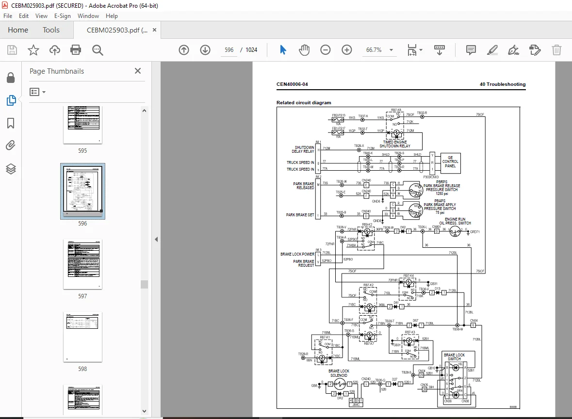
Fault Code A270: Brake lock switch power supply is not on when required 594
Related circuit diagram 596
Fault Code A271: Shifter not in gear 597
Related circuit diagram 598
Fault Code A272: Brake lock switch power supply is not off when required 599
Related circuit diagram 600
Fault Code A273: A fault has been detected in the hoist or steering pump filter pressure switch circuit 601
Related circuit diagram 601
Fault Code A274: A brake setting fault has been detected 602
Related circuit diagram 602
Fault Code A275: A starter has been detected as engaged without a cranking attempt 603
Related circuit diagram 604
Fault Code A276: The drive system data link is not connected 605
Related circuit diagram 606
Fault Code A277: Parking brake applied while loading 607
Related circuit diagram 608
Fault Code A278: Service brake applied while loading 609
Related circuit diagram 610
Fault Code A279: Low steering pressure switch is defective 611
Related circuit diagram 611
Fault Code A280: Steering accumulator bleed down switch is defective 612
Related circuit diagram 612
Fault Code A281: Brake lock degrade switch is defective 613
Related circuit diagram 614
Fault Code A282: The number of excessive cranking counts and jump starts without the engine running has reached 7 615
Related circuit diagram 616
Fault Code A283: An engine shutdown delay was aborted because the parking brake was not set 618
Related circuit diagram 619
Fault Code A284: An engine shutdown delay was aborted because the secondary shutdown switch was operated 620
Related circuit diagram 621
Fault Code A285: The parking brake was not set when the key switch was turned off 622
Related circuit diagram 623
Fault Code A286: A fault was detected in the shutdown delay relay circuit 624
Related circuit diagram 625
Fault Code A292: The shutdown delay relay has remained on after the latched key switch circuit is off 626
Related circuit diagram 627
Troubleshooting by fault code, Part 5 629
Fault Code A303: Shifter is defective 632
Related circuit diagram 633
Fault Code A304: Auto lube grease level fault 634
Related circuit diagram 634
Fault Code A305: Auto lube circuit is defective 635
Related circuit diagram 636
Fault Code A307: Both GE inverters are disabled 637
Related circuit diagram 637
Fault Code A309: No brakes applied when expected 638
Related circuit diagram 639
Fault Code A310: Low fuel warning 640
Related circuit diagram 641
Fault Code A311: Brake lock switch is on when it should not be 642
Related circuit diagram 643
Fault Code A312: DCDC converter 12 volt circuit sensing is producing low readings 644
Related circuit diagram 644
Fault Code A313: DCDC converter 12 volt circuit sensing is producing high readings 645
Related circuit diagram 645
Fault Code A315: DCDC converter 12 volt circuit is low 646
Related circuit diagram 647
Fault Code A316: Starter engagement has been attempted with engine running 648
Related circuit diagram 649
Fault Code A317: Operation of brake auto apply valve without a detected response 650
Related circuit diagram 651
Fault Code A318: Unexpected power loss to interface module 652
Related circuit diagram 652
Fault Code A320: Data link reports GE propel system caution fault but wired input does not 653
Related circuit diagram 654
Fault Code A321: Data link reports GE propel system temp caution fault but wired input does not 655
Related circuit diagram 656
Fault Code A322: Data link reports GE propel system reduced level fault but wired input does not 657
Related circuit diagram 658
Fault Code A323: Data link reports GE reduced retard level fault but wired input does not 659
Related circuit diagram 660
Fault Code A324: Data link reports DC link voltage but wired input does not 661
Related circuit diagram 662
Fault Code A325: Data link reports GE no propel/retard fault but wired input does not 663
Related circuit diagram 664
Fault Code A326: Data link reports GE no propel fault but wired input does not 665
Related circuit diagram 666
Fault Code A327: Data link reports GE at rest but wired input does not 667
Related circuit diagram 668
Fault Code A328: Drive system not powered up 669
Related circuit diagram 669
Fault Code A329: Data link reports the body is not down but wired input says it is 671
Related circuit diagram 672
Fault Code A330: Data link reports dynamic retard operating state but wired input does not 673
Related circuit diagram 674
Fault Code A334: Selector switch not in park when propel was either not ready or at rest 675
Related circuit diagram 675
Fault Code A335: Manual/Auto Apply Pressure Fault 676
Troubleshooting by fault code, Part 6 679
Fault Code A350: Overload on output 1B 681
Related circuit diagram 681
Fault Code A351: Overload on output 1E 682
Related circuit diagram 683
Fault Code A352: Overload on output 1H 684
Related circuit diagram 684
Fault Code A353: Overload on output 1J 685
Related circuit diagram 685
Fault Code A354: Overload on output 1K 686
Related circuit diagram 687
Fault Code A355: Overload on output 1L 688
Related circuit diagram 688
Fault Code A356: Overload on output 1M 689
Related circuit diagram 689
Fault Code A357: Overload on output 1N 690
Related circuit diagram 690
Fault Code A358: Overload on output 1P 691
Related circuit diagram 691
Fault Code A359: Overload on output 1R 692
Related circuit diagram 692
Fault Code A360: Overload on output 1S 693
Related circuit diagram 693
Fault Code A361: Overload on output 1T 694
Related circuit diagram 695
Fault Code A362: Overload on output 1U 696
Related circuit diagram 696
Fault Code A363: Overload on output 1X 697
Related circuit diagram 698
Fault Code A364: Overload on output 1Y 699
Related circuit diagram 699
Fault Code A365: Overload on output 1Z 700
Related circuit diagram 700
Cab air conditioning 703
Preliminary checks 705
Diagnosis of gauge readings and system performance 705
Troubleshooting by manifold gauge set readings 706
Reserve engine oil system 713
Pumping unit LED signals 715
Circuit fuses 715
Automatic lubrication (auto lube) system 717
Autolube troubleshooting chart 719
Steering system 723
Steering circuit troubleshooting chart 725
Steering circuit troubleshooting guidelines 727
Basic hydraulic system checks 728
System leakage check 729
Steering pump troubleshooting guide 731
Pump pressure control checks 734
Pump fails to unload 735
Pump fails to develop pressure 735
Pump slow in developing pressure 736
Pump control valve inspection and trouble shooting 736
Pump case drain check 738
Setting pump pressure controls 738
50 Disassembly and assembly 741
General information 741
Special tool list 743
Wheels, spindles and rear axle 747
General information for tires and rims 749
Storage and handling 749
Wheel stud maintenance 750
Rim components 751
Removal and installation of front wheel 752
Removal 752
Installation 752
Removal and installation of rear wheel 754
Removal 754
Installation 755
Removal and installation of tires 756
Removal 756
Installation 757
Removal and installation of front wheel hub and spindle 758
Removal 759
Spindle removal (off the truck) 762
Installation 764
Disassembly and assembly of front wheel hub and spindle 765
Disassembly 765
Cleaning and inspection 765
Assembly 767
Wheel bearing adjustment 767
Seal assembly gap check and adjustment 768
Brake installation 769
Speed sensor installation and adjustment 769
Removal and installation of rear axle 770
Removal 770
Cleaning and inspection 771
Installation 771
Removal and installation of anti-sway bar 771
Removal 771
Installation 772
Removal and installation of pivot pin 773
Removal 773
Installation 773
Pivot eye and bearing service 774
Bearing removal 774
Bearing installation 774
Pivot eye repair 775
Removal and installation of wheel motor 776
Preparation 776
Removal 776
Cleaning and inspection 777
Installation 779
Removal and installation of rear brake assembly 783
Removal 783
Installation 783
Brake system 787
Removal and installation of brake valve 789
Removal 789
Installation 790
Disassembly and assembly of brake valve/pedal assembly 790
Disassembly 790
Assembly 791
Removal and installation of dual relay valve 793
Removal 793
Installation 794
Removal and installation of brake manifold 795
Removal 795
Installation 795
Disassembly and assembly of brake manifold 796
Disassembly 796
Assembly 796
Removal and installation of brake accumulator 797
Removal 797
Installation 797
Disassembly and assembly of brake accumulator 798
Disassembly 798
Cleaning and inspection 799
Assembly 800
Disassembly and assembly of wheel brake 801
Disassembly 802
Cleaning and inspection 805
Assembly 806
Floating ring seal assembly and installation 809
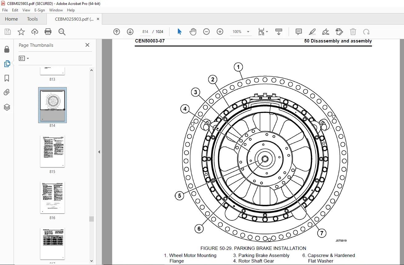
Removal and installation of parking brake 813
Removal 813
Installation 815
Disassembly and assembly of parking brake 815
Disassembly 815
Cleaning and inspection 816
Assembly 818
Cleaning and inspecting new discs 820
Steering system 823
Removal and installation of steering control unit 825
Removal 825
Installation 826
Disassembly and assembly of steering control unit 827
Disassembly 827
Assembly 829
Removal and installation of steering column 832
Removal 832
Inspection 832
Installation 833
Removal and installation of steering wheel 833
Removal 833
Installation 834
Removal and installation of bleeddown manifold 835
Removal 835
Installation 836
Removal and installation of flow amplifier 837
Removal 837
Installation 837
Disassembly and assembly of flow amplifier 837
Disassembly 837
Assembly 839
Removal and installation of steering cylinders and tie rod 840
Removal 840
Bearing replacement 840
Installation 840
Disassembly and assembly of steering cylinders 841
Disassembly 841
Assembly 842
Removal and installation of steering/brake pump 842
Removal 842
Installation 843
Disassembly and assembly of steering/brake pump 845
Disassembly 845
Inspection 848
Assembly 851
Driveshaft group 851
Rotating group 852
Removal and installation of bladder style steering accumulators 855
Removal 855
Installation 855
Disassembly and assembly of bladder style steering accumulators 856
Disassembly 856
Cleaning and Inspection 856
Bladder accumulator assembly 857
Removal and installation of piston style steering accumulators 859
Removal 859
Installation 860
Disassembly and Assembly of Piston Accumulators 861
Cleaning and Inspection 861
Assembly 862
Testing 862
Suspensions 865
Removal and installation of front suspension 867
Removal 867
Installation 868
Inspection 871
Minor front suspension repairs (lower bearing and seals) 874
Lower bearing retainer removal 874
Lower bearing retainer installation 874
Major front suspension rebuild 875
Disassembly 875
Assembly 876
Removal and installation of rear suspension 878
Removal 879
Installation 881
Disassembly and assembly of rear suspension 881
Disassembly 881
Cleaning and Inspection 882
Assembly 882
Hoist circuit 885
Removal and installation of hoist pump 887
Removal 887
Installation 888
Disassembly and assembly of hoist pump 889
Disassembly 889
Inspection 892
Assembly 892
Removal and installation of hoist valve 897
Removal 897
Installation 898
Disassembly and assembly of hoist valve 898
O-ring replacement 898
Disassembly of inlet section 899
Assembly of inlet section 900
Disassembly of rear spool section 900
Assembly of rear spool section 903
Disassembly of front spool section 904
Assembly of front spool section 905
Overcenter valve manifold service 905
Removal and installation of hoist pilot valve 906
Removal 906
Installation 906
Disassembly and assembly of hoist pilot valve 907
Disassembly 907
Cleaning and inspection 908
Assembly 908
Removal and installation of hoist cylinders 909
Removal 909
Installation 910
Disassembly and assembly of hoist cylinders 911
Disassembly 911
Cleaning and inspection 913
Installation of the quill 914
Assembly 916
Operator cab 919
Removal and installation of operator cab 921
Removal 922
Installation 923
Removal and installation of cab door 924
Removal 924
Installation 924
Disassembly and assembly of cab door 924
Removing door panel 924
Installing door panel 925
Replacing the door window regulator 925
Replacing door handle or latch assembly 926
Replacing door assembly seal and door hinge seal 927
Replacing door opening seal 927
Removing door glass 928
Installing door glass 930
Adjustment of cab door 931
Door jamb bolt adjustment 931
Door handle plunger adjustment 933
Removal and installation of side window glass 934
Recommended tools and supplies 934
Removal 934
Installation 934
Removal and installation of windshield and rear window glass 935
Removal 935
Installation 935
Removal and installation of windshield wiper motor 937
Removal 937
Installation 937
Removal and installation of windshield wiper arm 938
Removal 938
Installation 938
Removal and installation of windshield wiper linkage 938
Removal 938
Installation 939
Removal and installation of operator seat 939
Inspection 939
Removal 939
Installation 939
Replacing the Seat Compressor 940
Removal and installation of passenger seat 945
Removal 945
Installation 945
Removal and installation of seat belts (standard seats) 946
Removal 946
Installation 946
Removal and installation of seat belts (optional seats) 948
General 948
Removal 948
Installation 950
Body and structures 953
Removal and installation of dump body 955
Removal 955
Inspection 956
Installation 957
Removal and installation of body pads 958
Removal 958
Installation 958
Body pad shimming procedure 959
Removal and installation of diagonal ladder/ hood and grille assembly 960
Removal 960
Installation 960
Removal and installation of right deck 962
Removal 962
Installation 962
Removal and installation of left deck 964
Removal 964
Installation 964
Removal and installation of fuel tank 966
Removal 966
Cleaning and inspection 966
Installation 968
Removal and installation of fuel gauge sender 969
Removal (earlier models) 969
Installation (earlier models) 969
Removal (later models) 969
Installation (later models) 969
Disassembly and assembly of fuel tank breather 970
Disassembly 970
Assembly 970
Removal and installation of hydraulic tank 971
Removal 971
Installation 971
Cab air conditioning 973
Replacement of air conditioning system components 975
Hoses and fittings 975
Lines 975
Expansion valve 975
Receiver-drier 975
Thermostat 975
Compressor 976
Accumulator 976
Clutch 976
Power module 979
Removal and installation of power module 981
General 981
Preparation 981
Removal 982
Installation 988
Exhaust tube installation 990
Exhaust blanket installation 990
Removal and installation of alternator 991
Removal 991
Installation 993
Removal and installation of engine 996
Removal 996
Service 996
Installation 996
Removal and installation of radiator 997
Removal 997
Installation 999
Repairing the radiator 1000
Internal inspection 1000
External cleaning 1000
Disassembly 1001
Cleaning and inspection 1002
Assembly 1002
Pressure testing 1003
90 Diagrams and drawings 1005
Hydraulic circuit diagrams 1005
Electrical circuit diagrams 1011
DESCRIPTION:
Komatsu 960E-2 DUMP TRUCK Shop Manual CEBM025903 – PDF DOWNLOAD
- SERIAL NUMBERS 960E-2 A30027 – A30073
Composition of shop manual
This shop manual contains the necessary technical information for services performed in a workshop.
For ease of understanding, the manual is divided into the following sections.
00. Index and foreword
This section explains the shop manuals list, table of contents, safety, and basic information.
01. Specification
This section explains the specifications of the machine.
10. Structure, function and maintenance standard
This section explains the structure, function, and maintenance standard values of each component. The
structure and function sub-section explains the structure and function of each component. It serves not
only to give an understanding of the structure, but also serves as reference material for troubleshooting.
The maintenance standard sub-section explains the criteria and remedies for disassembly and service.
20. Standard value table
This section explains the standard values for new machine and judgment criteria for testing, adjusting,
and troubleshooting. This standard value table is used to check the standard values in testing and adjusting
and to judge parts in troubleshooting.
30. Testing and adjusting
This section explains measuring instruments and measuring methods for testing and adjusting, and
method of adjusting each part. The standard values and judgment criteria for testing and adjusting are
explained in Testing and adjusting.
40. Troubleshooting
This section explains how to find out failed parts and how to repair them. The troubleshooting is divided by
failure modes.
50. Disassembly and assembly
This section explains the special tools and procedures for removing, installing, disassembling, and
assembling each component, as well as precautions for them. In addition, tightening torque and weight of
components are also explained.
90. Diagrams and drawings
This section gives hydraulic circuit diagrams and electrical circuit diagrams.
Revision and distribution
Any additions, revisions, or other change of notices will be sent to KOMATSU distributors. Get the most up-todate
information before you start any work
G.B 21/12/24


