
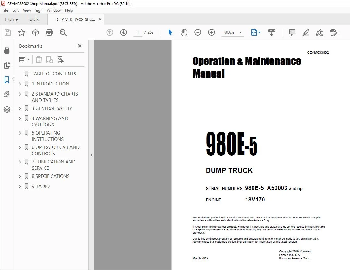
Komatsu 980E-5 Dump Truck Operation & Maintenance Manual CEAM033902 – PDF DOWNLOAD
Original price was: $86.95.$29.95Current price is: $29.95.
Komatsu 980E-5 Dump Truck Operation & Maintenance Manual CEAM033902 – PDF DOWNLOAD
SERIAL NUMBERS 980E-5 A50003 and up
ENGINE 18V170
Description
Komatsu 980E-5 Dump Truck Operation & Maintenance Manual CEAM033902 – PDF DOWNLOAD
IMAGES PREVIEW OF THE MANUAL:
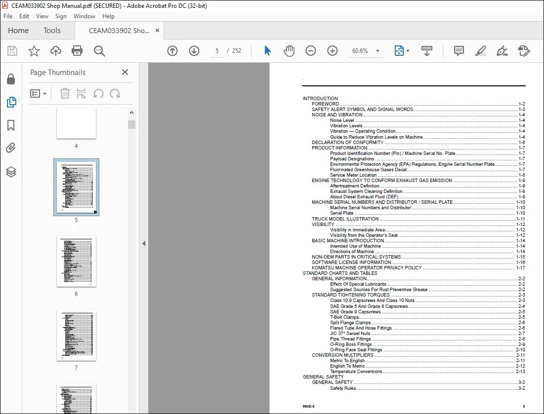
TABLE OF CONTENTS:
Komatsu 980E-5 Dump Truck Operation & Maintenance Manual CEAM033902 – PDF DOWNLOAD
INTRODUCTION
FOREWORD 1-2
SAFETY ALERT SYMBOL AND SIGNAL WORDS 1-3
NOISE AND VIBRATION 1-4
Noise Level 1-4
Vibration Levels 1-4
Vibration — Operating Condition 1-4
Guide to Reduce Vibration Levels on Machine 1-4
DECLARATION OF CONFORMITY 1-6
PRODUCT INFORMATION 1-7
Product Identification Number (Pin) / Machine Serial No Plate 1-7
Payload Designations 1-7
Environmental Protection Agency (EPA) Regulations, Engine Serial Number Plate 1-7
Fluorinated Greenhouse Gases Decal 1-7
Service Meter Location 1-8
ENGINE TECHNOLOGY TO CONFORM EXHAUST GAS EMISSION 1-9
Aftertreatment Definition 1-9
Exhaust System Cleaning Definition 1-9
About Diesel Exhaust Fluid (DEF) 1-9
MACHINE SERIAL NUMBERS AND DISTRIBUTOR / SERIAL PLATE 1-10
Machine Serial Numbers and Distributor 1-10
Serial Plate 1-10
TRUCK MODEL ILLUSTRATION 1-11
VISIBILITY 1-12
Visibility in Immediate Area 1-12
Visibility from the Operator’s Seat 1-12
BASIC MACHINE INTRODUCTION 1-14
Intended Use of Machine 1-14
Directions of Machine 1-14
NON-OEM PARTS IN CRITICAL SYSTEMS 1-15
SOFTWARE LICENSE INFORMATION 1-16
KOMATSU MACHINE OPERATOR PRIVACY POLICY 1-17
STANDARD CHARTS AND TABLES
GENERAL INFORMATION 2-2
Effect Of Special Lubricants 2-2
Suggested Sources For Rust Preventive Grease 2-2
STANDARD TIGHTENING TORQUES 2-3
Class 10 9 Capscrews And Class 10 Nuts 2-3
SAE Grade 5 And Grade 8 Capscrews 2-4
SAE Grade 9 Capscrews 2-5
T-Bolt Clamps 2-5
Split Flange Clamps 2-6
Flared Tube And Hose Fittings 2-6
JIC 37° Swivel Nuts 2-7
Pipe Thread Fittings 2-8
O-Ring Boss Fittings 2-9
O-Ring Face Seal Fittings 2-10
CONVERSION MULTIPLIERS 2-11
Metric To English 2-11
English To Metric 2-12
Temperature Conversions 2-13
GENERAL SAFETY
GENERAL SAFETY 3-2
Safety Rules 3-2
980E-5 3
Truck Safety Features 3-2
Clothing And Personal Items 3-2
Leaving The Operator’s Seat 3-2
Mounting And Dismounting 3-2
Fire Extinguishers And First Aid Kits 3-2
Precautions For High Temperature Fluids 3-3
Asbestos Dust Hazard Prevention 3-3
Fire Prevention 3-3
Preventing Injury From Work Equipment 3-3
Precautions Related to Protective Structures 3-4
Unauthorized Modification 3-4
Precautions For Optional Attachments 3-4
Precautions When Starting The Machine 3-4
PRECAUTIONS WHEN GETTING ON OR OFF MACHINE 3-5
Precautions When Getting On And Off The Machine 3-5
Mounting and Dismounting 3-5
Emergency Egress Ladders 3-5
Lifting of Personnel Prohibited 3-6
People on Dump Body 3-6
When Leaving the Machine 3-6
Emergency Exit From Operator’s Cab 3-6
PRECAUTIONS FOR TRUCK OPERATION 3-7
Safety Is Thinking Ahead 3-7
Safety At The Worksite 3-7
Preparing For Operation 3-7
Ventilation For Enclosed Areas 3-7
Method To Adjust Mirrors 3-7
Before Starting The Engine 3-8
Seat Operation 3-8
Seat Belts And Tethers 3-9
Precautions When Traveling In Forward Or Reverse 3-9
Precautions To Tow The Machine 3-10
Periodic Replacement Of Defined Life Parts 3-10
Operation Of Urea Selective Catalytic Reduction (SCR) System 3-10
Operation Of SCR System In Cold Weather 3-11
Precautions For Diesel Exhaust Fluid (DEF) 3-11
Precautions For Adding 3-11
Precautions For Storing 3-11
Precautions For Fire Hazard And Leakage 3-11
Cold Weather Operation 3-12
Other Precautions 3-12
Crystallization Management 3-12
OPERATING THE MACHINE 3-13
General Information 3-13
Starting The Engine 3-13
Starting Engine in Cold Weather 3-13
Start Engine with Auxiliary Engine Starting Connector Precaution 3-14
Traveling In The Machine 3-14
Traveling On Slopes 3-14
Traveling On Snow 3-14
Traveling Near High Voltage Cables 3-14
Traveling On Loose Ground 3-15
Good Visibility 3-15
Avoid Damage To The Dump Body 3-15
4 980E-5
Safe Parking Of The Machine 3-15
Loading The Machine 3-15
Dumping The Machine 3-15
Towing The Machine 3-16
EXTERIOR LIGHTING 3-17
Fog Lights 3-17
Headlights 3-17
Mirror Mounted Backup Lights 3-17
Deck Mounted Flood Lights 3-17
Brake Lights 3-18
Retard Lights 3-18
Clearance/Turn Signal Lights 3-18
Retard Lights 3-18
Brake Lights 3-18
Backup Alarm 3-18
LED Backup Lights 3-18
PRECAUTIONS FOR MAINTENANCE 3-19
BEFORE PERFORMING MAINTENANCE 3-19
Electrical System Isolation 3-19
Securing The Dump Body 3-20
DURING MAINTENANCE 3-21
Warning Tag 3-21
Lock Out/Tag Out 3-22
Proper Tools 3-22
Attachments 3-22
Working Under The Machine 3-22
Keeping The Machine Clean 3-22
Adding Fuel Or Oil To The Machine 3-23
Radiator Coolant Level 3-23
Use Of Lighting 3-23
Handling High Pressure Hoses 3-23
Precautions With High Pressure Oil 3-23
Maintenance Near High Temperatures And High Pressures 3-23
Rotating Fan And Belts 3-23
Accumulators, Suspension Cylinders and Gas Springs Precaution 3-24
Waste Materials 3-24
Use Of Tie-Off Anchor During Maintenance 3-24
Tire Selection 3-24
Handling Tires 3-25
METHOD TO EXAMINE AND INFLATE TIRE 3-25
Tire Maintenance 3-26
Storing Tires After Removal 3-26
Battery Hazard Prevention 3-26
Jump Starting With Jumper Cables 3-27
Jump Starting With Receptacles 3-28
WHEN REPAIRS ARE NECESSARY 3-29
Observe The Following Precautions 3-29
SPECIAL PRECAUTIONS 3-30
Preliminary Procedures Before Welding Or Performing Maintenance 3-30
Engine Shutdown Procedure Before Welding Or Performing Maintenance 3-30
Before Welding On The Machine, Obey The Following Guidelines: 3-30
Discharging Control Cabinet Capacitors 3-31
JACK POINT LOCATIONS 3-32
WARNING AND CAUTIONS
980E-5 5
GENERAL INFORMATION 4-2
PIN PLATE 4-2
GRADE SPEED CHART 4-3
SAFETY LABEL OVERVIEW 4-4
GENERAL SAFETY LABEL LOCATIONS 4-4
SAFETY LABELS 4-7
LUBRICATION CHART 4-23
OPERATING INSTRUCTIONS
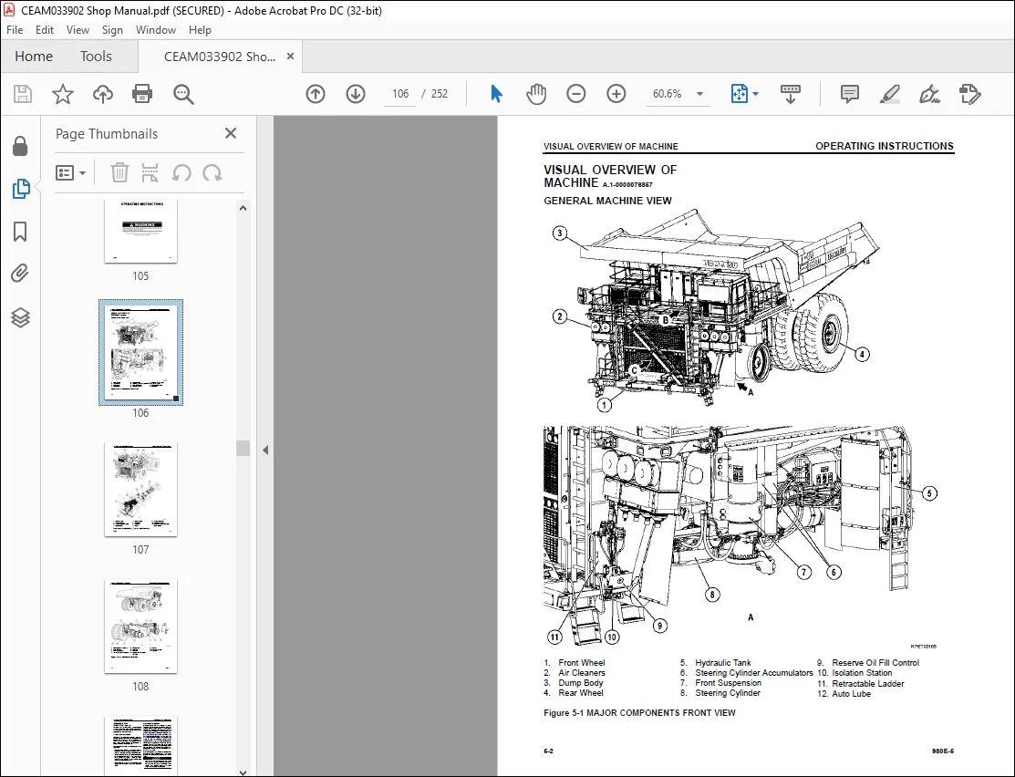
VISUAL OVERVIEW OF MACHINE 5-2
GENERAL MACHINE VIEW 5-2
PREPARING FOR OPERATION 5-5
Safety Is Thinking Ahead 5-5
Walk Around Inspection 5-5
RETRACTABLE LADDER SYSTEM (If Equipped) 5-10
General Information 5-10
Ladder System Description 5-10
Ladder System Operation 5-10
Retractable Ladder Switch 5-10
Ground Level Control Switch 5-11
Emergency Down Valve 5-11
PRE-SHIFT BRAKE TEST 5-12
Operation 5-12
Service Brake Test 5-13
Parking Brake Test 5-13
Retard System Test 5-14
Brake Test Exit Criteria 5-14
TRUCK OPERATION 5-15
ENGINE START-UP SAFETY 5-15
After Engine Has Started 5-15
MACHINE OPERATION SAFETY PRECAUTIONS 5-16
Machine Operation On The Haul Road 5-17
Starting On A Grade With A Loaded Truck 5-17
Retarding On A Grade 5-17
Passing 5-18
Loading 5-18
Overload Speed Limit Function 5-18
Dumping 5-18
Emergency Dump Procedure 5-19
Lowering The Dump Body (When Dumping On Flat Ground) 5-20
Lowering The Dump Body (When Dumping Over A Berm Or Into A Crusher) 5-20
ASSISTED BRAKE MANAGEMENT (ABM) (If Enabled) 5-21
Assisted Brake Management (ABM) 5-21
Limitations 5-21
ABM Operation 5-22
Moving on ABM 5-22
Holding Stopped on ABM 5-23
Fault Conditions with ABM 5-23
Wheel Brake Lock Switch Interaction with ABM 5-23
Opposite Motion Speed Thresholds on ABM 5-23
No Pedal Input Brake Release on ABM 5-23
Inverter Cutout on ABM 5-23
ABM Operator Inhibit 5-23
ABM Temporary Disable 5-23
SUDDEN LOSS OF ENGINE POWER OR LOSS OF DRIVE SYSTEM FUNCTION 5-23
6 980E-5
EMERGENCY STEERING SYSTEM 5-24
Operation 5-24
Pre-Operation Testing 5-24
Additional Guidelines 5-25
KOMVISION (If Equipped) 5-25
KomVision System Precautions 5-25
Component Locations 5-26
Monitor Panel 5-31
Brightness Switches 5-31
System Power Status Indicator 5-31
Speed Setting Lock Switch 5-31
Camera Switches 5-32
Monitor Display Mode Switch 5-32
Reference Line Display Switch 5-32
Lower Body Display Switch 5-32
Object Clear Switch 5-32
Monitor Display 5-32
Camera Display Modes 5-34
Bird’s Eye Views 5-35
Reference Lines 5-35
Dump Body Status Display 5-35
Error Code Display 5-36
Initial Setting Screen 5-37
Radar System 5-37
Object Detection Range 5-37
Object Detection Warnings 5-38
Object Clear 5-41
Start-Up Inspection 5-41
FUEL DEPLETION 5-42
SAFE PARKING PROCEDURES 5-42
NORMAL ENGINE SHUTDOWN PROCEDURE 5-43
DISABLED TRUCK CONNECTORS 5-44
GENERAL INFORMATION 5-44
STEERING AND BRAKE SYSTEM 5-44
Hookup 5-44
HOIST SYSTEM 5-45
Hookup 5-45
Dumping Procedure 5-46
TOWING 5-47
SPECIAL WIRING HARNESS 5-48
TOWING PROCEDURE 5-48
Transportation and Lifting 5-50
PAYLOAD METER IV SYSTEM 5-51
GENERAL INFORMATION 5-51
Data Summary 5-51
Data Gathering 5-51
COMPONENT DESCRIPTION 5-51
Electronic Dash Displays 5-51
Operator Input Switches 5-52
Brake Lock Switch 5-52
Payload Meter Module (PLM) 5-52
Load Lights 5-54
Keyswitch Input 5-54
Payload Meter (PLM) Power 5-54
980E-5 7
SCOREBOARD 5-54
OPERATOR’S DISPLAY AND SWITCH 5-55
Setting The Operator ID 5-55
Load And Ton Counter 5-55
Viewing Live Sensor Data 5-55
PAYLOAD OPERATION & CALCULATION 5-55
Description of Haul Cycle States 5-55
Haul Cycle Description 5-56
Load Calculation 5-56
Carry Back 5-56
Measurement Accuracy 5-57
SOURCES FOR PAYLOAD ERROR 5-57
Payload Error 5-57
Critical Suspension Factors: 5-57
Loading Conditions 5-57
Pressure Sensors 5-57
Swingloads 5-58
DOWNLOADING HAUL CYCLE DATA 5-58
VIEWING ALARM DATA 5-59
DOWNLOADING ALARM DATA 5-60
AUTOMATIC LUBRICATION SYSTEM 5-62
GENERAL INFORMATION 5-62
COMPONENT DESCRIPTION 5-62
Filter 5-63
Hydraulic Motor and Pump 5-63
Grease Reservoir 5-63
Pressure Reducing Valve 5-63
Flow Control Valve 5-64
Solenoid Valve 5-64
Orifice Disc 5-64
Vent Valve 5-64
Interface Module 5-64
Injectors 5-65
Grease Pressure Failure Switch 5-66
Relief Valve (Unloader Valve) 5-66
SYSTEM OPERATION 5-66
Filling The Reservoir 5-66
Priming The Automatic Lubrication System 5-67
PREVENTIVE MAINTENANCE PROCEDURES 5-67
Daily Lubrication System Inspection 5-67
250 Hour Inspection 5-68
1000 Hour Inspection 5-68
SYSTEM CHECKOUT 5-68
General Checks 5-68
Lubrication Cycle Operation 5-69
OPERATOR CAB AND CONTROLS
CAB INTERIOR 6-2
STEERING WHEEL AND CONTROLS 6-3
Horn Button 6-3
Speed Control Lever 6-3
Tilt / Telescope Lever 6-3
Multi-Function Turn Signal Switch 6-4
Turn Signal Operation 6-4
Windshield Wiper Operation 6-4
8 980E-5
High Beam Headlight Operation 6-4
PEDALS 6-5
Dynamic Retarding 6-5
Brake/Retarder Pedal 6-5
Accelerator Pedal 6-5
CENTER CONSOLE 6-6
Raising The Dump Body 6-6
Lowering The Dump Body 6-6
Directional Control Lever 6-6
Override / Fault Reset Switch 6-7
Window Control Switches 6-7
Traction Control Switch 6-7
Speed Control Switch 6-7
Wheel Brake Lock Control Switch 6-7
Data Store Button 6-8
12V Auxiliary Power Outlets 6-8
Communication Radio Power Outlet 6-8
Operator and Passenger Seat Outlets 6-8
Fire Suppression Control Outlet 6-8
DIAGNOSTIC PORTS 6-9
Third Party 6-9
KOM-Net 6-9
Engine Diagnostic 6-9
PC Local Area Network (LAN) Ethernet 6-9
Drive System Controller (DSC) 6-9
Interface Module (IM) 6-9
SAT Connector 6-9
OPERATOR SEAT, PREMIUM (if equipped) 6-10
Adjustment 6-10
OPERATOR SEAT, STANDARD 6-12
Adjustment 6-12
PASSENGER SEAT, PREMIUM (if equipped) 6-14
Adjustment 6-14
PASSENGER SEAT, STANDARD 6-16
Adjustment 6-16
INSTRUMENT PANEL 6-18
Control Symbols 6-18
Heater/Air Conditioner Controls 6-19
Status Indicator Light Panel 6-19
Hydraulic Oil Temperature Gauge 6-19
Coolant Temperature Gauge 6-19
Speedometer/Digital Display 6-19
Panel Light Dimmer 6-20
Fuel Level Gauge 6-20
Diesel Exhaust Fluid (DEF) Level Gauge (when equipped) 6-20
Drive System Temperature Gauge (when equipped) 6-20
Hazard Warning Light 6-20
Emergency Engine Stop Switch 6-20
KomVision Monitor 6-20
Tray 6-20
Modular Mining Monitor 6-20
Radio 6-21
Mode Switches 6-21
Heated Mirror Switch 6-21
980E-5 9
Engine Warm Up 6-21
Key Switch 6-21
Digital Display Contrast Buttons 6-21
Hazard Warning Light Switch 6-21
Rotating Beacon Light Switch (Optional) 6-21
Ladder Light Switch 6-21
Backup Light Switch 6-22
Fog Light Switch 6-22
Headlight/Panel Illumination Light Switch 6-22
HEATER/AIR CONDITIONER CONTROLS 6-23
Fan Speed Up/Down 6-23
Celsius Or Fahrenheit 6-23
LED Digital Display 6-23
Economy Mode (ECON) 6-23
Temperature Up/Down 6-23
Defrost 6-23
AUTO 6-24
ON/OFF 6-24
STATUS INDICATOR LIGHT PANEL 6-25
STATUS INDICATOR LIGHT SYMBOLS 6-25
Turn Signal Indicators 6-25
High Beam Headlights 6-25
No DC Link Voltage 6-25
Seat Belt Warning 6-26
Retractable Ladder Down 6-26
Retarding Grid Dryer 6-26
Snapshot In Progress 6-26
Pantograph Energized 6-26
Repair Monitor 6-26
Pantograph Up 6-26
Traction Control OFF 6-26
Service Brake 6-26
Engine Warm Up 6-26
No Propel 6-27
Assisted Brake Management (ABM) 6-27
Engine Shutdown Delay 6-27
Propel System Not Ready 6-27
Dynamic Retarding 6-27
Parking Brake 6-27
Body Up 6-27
Wheel Brake Lock 6-28
DIGITAL DISPLAY OPERATION 6-29
Toggling Through Main Level Screens 6-29
Toggling Through Warning Screens 6-30
Entering Payload Meter Data 6-31
KOMTRAX Plus 2 6-32
KOMTRAX Plus 2 OPERATION 6-32
POWER SUPPLY FOR KOMTRAX Plus 2 6-32
OBSERVANCE OF THE APPLICABLE LAWS AND REGULATIONS, EXEMPTION 6-32
IRIDIUM 6-33
KOMATSU WIRELESS BRIDGE (KWB) 6-34
General Information 6-34
ONBOARD CONTROLLER ACCESS 6-34
Wireless Access 6-34
10 980E-5
FUSES AND CIRCUIT BREAKERS 6-35
VEHICLE ELECTRICAL CENTER 89 6-35
VEHICLE ELECTRICAL CENTER 90 6-37
VEHICLE ELECTRICAL CENTER 91 6-39
VEHICLE ELECTRICAL CENTER 92 6-41
REAR TERMINAL MINI FUSE AND RELAY BLOCKS (RTMR) 6-42
CIRCUIT BREAKERS 6-44
LUBRICATION AND SERVICE
GENERAL INFORMATION 7-2
HYDRAULIC SYSTEM SERVICE 7-2
Hydraulic Tank 7-2
Hydraulic Filters 7-3
Hydraulic Pump Drive Shaft 7-3
WHEEL MOTOR SERVICE 7-4
COOLANT LEVEL SERVICE 7-4
Radiator Filling Procedure 7-4
Coolant Specifications 7-4
Unacceptable Practices 7-4
CAB AIR FILTER SERVICE 7-5
FUEL SYSTEM SERVICE 7-5
Fuel Tank Cleaning 7-5
INTAKE AIR CLEANER SERVICE 7-6
FRONT WHEEL SERVICE 7-7
Oil Sampling 7-7
FRONT ENGINE MOUNT TRUNNION SERVICE 7-7
QUICK FILL SERVICE CENTER 7-7
TIE ROD INSPECTION AND TORQUE PROCEDURE 7-8
EXHAUST AFTER TREATMENT SERVICE 7-9
DEF Filters 7-9
LUBRICATION CHART 7-10
PERIODIC REPLACEMENT OF DEFINED LIFE PARTS 7-11
INITIAL 50 HOUR LUBRICATION AND MAINTENANCE 7-12
INITIAL 100 HOUR LUBRICATION AND MAINTENANCE 7-13
EVERY 250 HOUR LUBRICATION AND MAINTENANCE 7-14
EVERY 500 HOUR LUBRICATION AND MAINTENANCE 7-15
EVERY 1000 HOURS LUBRICATION AND MAINTENANCE 7-17
EVERY 2500 HOUR MAINTENANCE 7-19
EVERY 3000 HOUR LUBRICATION AND MAINTENANCE 7-20
EVERY 5000 HOUR MAINTENANCE 7-21
EVERY 6500 HOUR MAINTENANCE 7-22
EVERY 18000 HOUR MAINTENANCE 7-23
SPECIFICATIONS
MAJOR COMPONENT DESCRIPTION 8-2
Truck and Engine 8-2
Traction Alternator 8-2
Cooling Group and Wheel Cooling Blowers 8-2
Main Control Cabinet 8-2
AC Induction Traction Motorized Wheels 8-2
Suspension 8-2
Operator’s Cab 8-2
Power Steering 8-2
Dynamic Retarding Grid 8-2
Brake System 8-2
SPECIFICATIONS 8-4
980E-5 11
Engine 8-4
AC Electric Drive System 8-4
Dynamic Retarding 8-4
Battery Electric System 8-4
Service Capacities 8-4
Hydraulic Systems 8-4
Service Brakes 8-5
Steering 8-5
Standard Dump Body Capacities and Dimensions 8-5
Tires 8-5
Weight Distribution 8-5
Overall Truck Dimensions 8-5
RADIO
AM/FM RADIO / CD / MP3 / USB / iPOD™ / AUX PLAYER 9-2
Phone/Bluetooth Button 9-2
Digital Display 9-2
CD Slot 9-2
Volume Knob/OK Button 9-2
SRC/PWR (Source/Power) Button 9-3
NEXT Button 9-3
Eject Button 9-3
USB Connection Port 9-3
Auxiliary Jack Port 9-3
SCAN/ASCN (Scan/Autoscan) Button 9-3
PREV (Previous) Button 9-3
DISP (Display) Button 9-3
ESC (Escape) Button 9-3
RDM (Random) Button 9-3
RPT (Repeat) Button 9-4
Clock/Alarm Button 9-4
Adjusting the Clock 9-4
Browse Button 9-4
Play/Pause Button 9-4
Preset Buttons 9-4
Station Presets 9-4
Storing Radio Station Presets 9-4
Customer Support: [email protected]
https://vimeo.com/742223084
DESCRIPTION:
Komatsu 980E-5 Dump Truck Operation & Maintenance Manual CEAM033902 – PDF DOWNLOAD
SERIAL NUMBERS 980E-5 A50003 and up
ENGINE 18V170
FOREWORD :
- The operation and maintenance manual explains the operation, methods of inspection and maintenance for this
machine that must be obeyed to use this machine safely. Most accidents are caused by the failure to follow
fundamental safety rules for the operation and maintenance of machines. - The precautions in this manual must be followed at all times. Accidents can be prevented by knowing conditions
ahead of time that may cause a hazard when performing operation and maintenance. - Komatsu cannot predict every circumstance that might involve a potential hazard when the machine is used.
- Therefore, the safety messages in this manual and on the machine may not include all possible safety
precautions. If you carry out any operation, inspection or maintenance under conditions not described in this
manual, understand it is your responsibility to take the necessary precautions to ensure safety. In no event
should you or others engage in prohibited uses or actions described in this manual. - Always keep this Operation & Maintenance Manual in the location shown on the right so that all relevant
personnel can read it at any time
PLEASE NOTE:
- This is the same manual used by the dealers to diagnose and troubleshoot your vehicle
- You will be directed to the download page as soon as the purchase is completed. The whole payment and downloading process will take anywhere between 2-5 minutes
- Need any other service / repair / parts manual, please feel free to contact [email protected] . We still have 50,000 manuals unlisted
S.V



