
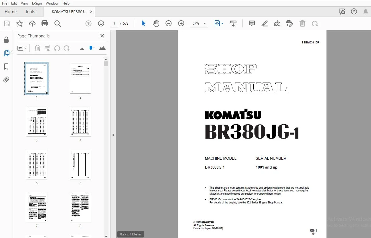
KOMATSU BR380JG-1 SHOP MANUAL SEBM034105 – PDF DOWNLOAD
$30.95
KOMATSU BR380JG-1 SHOP MANUAL SEBM034105 – PDF DOWNLOAD
Description
KOMATSU BR380JG-1 SHOP MANUAL SEBM034105 – PDF DOWNLOAD
FILE DETAILS:
KOMATSU BR380JG-1 SHOP MANUAL SEBM034105 – PDF DOWNLOAD
Language : English
Pages : 573
Downloadable : Yes
File Type : PDF
IMAGES PREVIEW OF THE MANUAL:
TABLE OF CONTENTS:
KOMATSU BR380JG-1 SHOP MANUAL SEBM034105 – PDF DOWNLOAD
COVER..........................................................................................................................  1
CONTENTS.......................................................................................................................  2
LIST OF REVISED PAGES..........................................................................................................  3
SAFETY.........................................................................................................................  7
	SAFETY NOTICE..............................................................................................................  7
FOREWORD.......................................................................................................................  9
	GENERAL....................................................................................................................  9
	HOW TO READ THE SHOP MANUAL................................................................................................ 10
	HOISTING INSTRUCTIONS...................................................................................................... 11
	METHOD OF DISASSEMBLING, CONNECTING PUSH-PULL TYPE COUPLER................................................................. 12
	COATING MATERIALS.......................................................................................................... 14
	STANDARD TIGHTENING TORQUE................................................................................................. 16
	ELECTRIC WIRE CODE......................................................................................................... 19
	CONVERSION TABLE........................................................................................................... 20
	UNITS...................................................................................................................... 26
01 GENERAL..................................................................................................................... 27
	SPECIFICATION DRAWINGS..................................................................................................... 28
	SPECIFICATIONS............................................................................................................. 29
	WEIGHT TABLE............................................................................................................... 31
	FUEL, COOLANT AND LUBRICANTS............................................................................................... 32
10 STRUCTURE, FUNCTION AND MAINTENANCE STANDARD................................................................................ 35
	ENGINE RELATED PARTS....................................................................................................... 36
	RADIATOR, OIL COOLER, AFTERCOOLER.......................................................................................... 37
	POWER TRAIN................................................................................................................ 38
	DRIVE SYSTEM FOR COMPONENTS................................................................................................ 39
	FINAL DRIVE................................................................................................................ 40
	TRACK FRAME AND RECOIL SPR................................................................................................. 42
	IDLER...................................................................................................................... 44
	CARRIER ROLLER............................................................................................................. 46
	TRACK ROLLER............................................................................................................... 47
	TRACK SHOE................................................................................................................. 48
	ARRANGEMENT OF HYDRAULIC EQUIPMENT......................................................................................... 52
	HYDRAULIC TANK AND HYDRAULIC OIL FILTER.................................................................................... 53
	HYDRAULIC PUMP............................................................................................................. 54
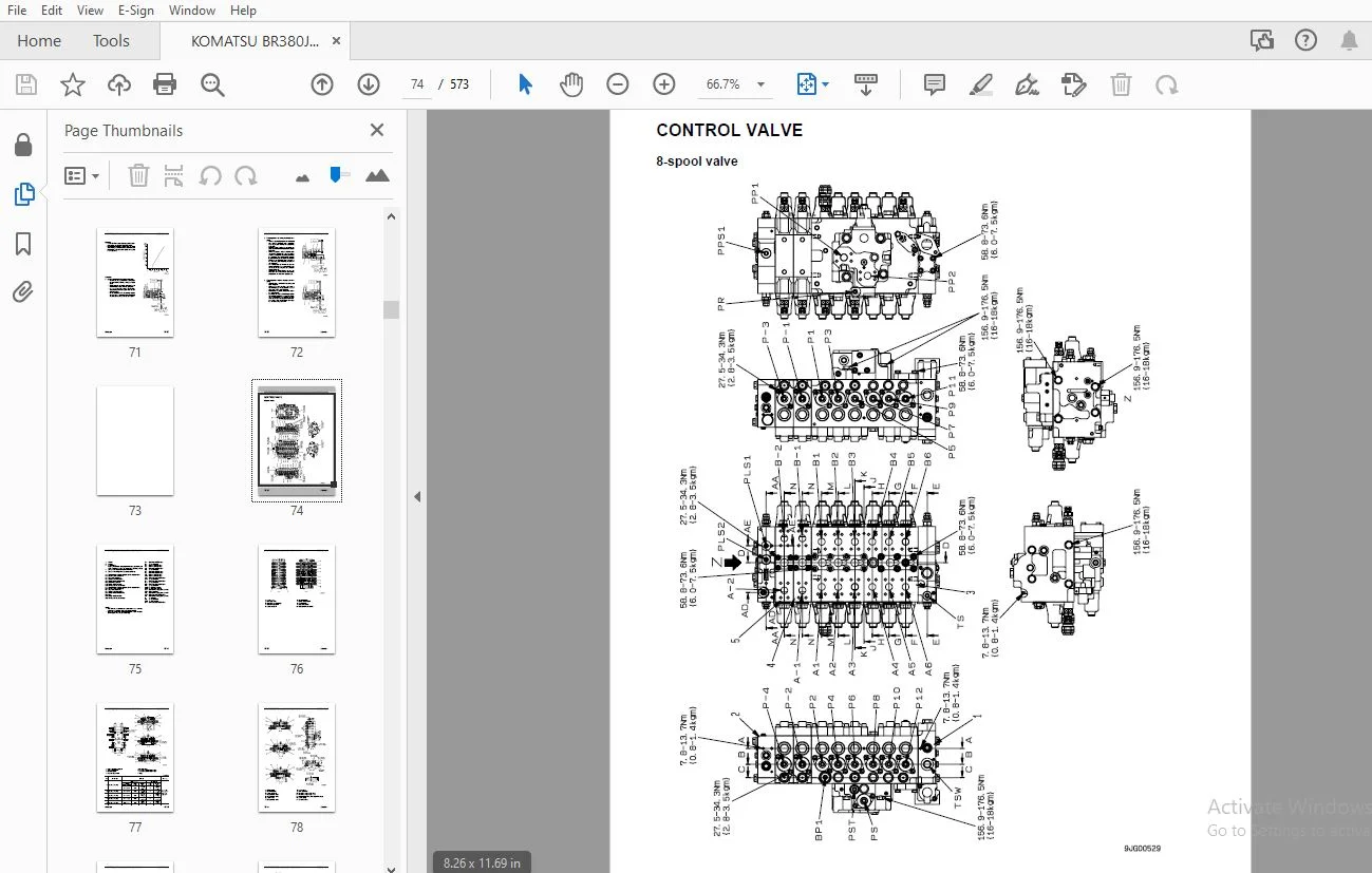
	CONTROL VALVE.............................................................................................................. 74
	SELF-REDUCING PRESSURE VALVE............................................................................................... 82
	CLSS....................................................................................................................... 87
	CRUSHER MOTOR..............................................................................................................104
	GRIZZLY FEEDER MOTOR.......................................................................................................108
	CONVEYOR MOTOR.............................................................................................................109
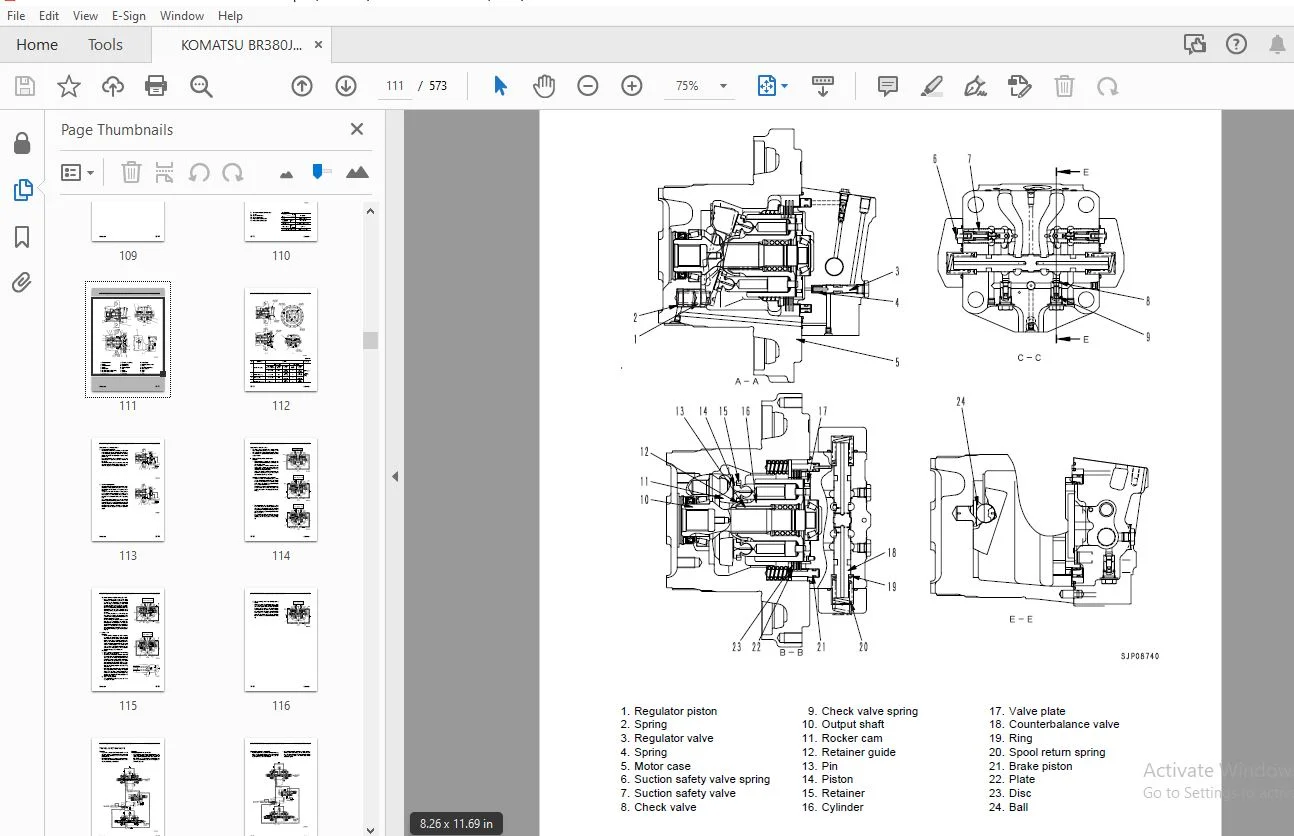
	TRAVEL MOTOR...............................................................................................................110
	TRAVEL JUNCTION VALVE......................................................................................................117
	VALVE CONTROL..............................................................................................................119
	TRAVEL PPC VALVE...........................................................................................................120
	SOLENOID VALVE.............................................................................................................129
	EPC VALVE..................................................................................................................131
	ELECTROMAGNETIC SELECTOR VALVE.............................................................................................135
	GRIZZLY FEEDER SEMIAUTOMATIC SYSTEM........................................................................................137
	ABNORMAL LOAD STOP SYSTEM..................................................................................................138
	PRIMARY BELT CONVEYOR......................................................................................................139
	GRIZZLY FEEDER.............................................................................................................140
	CRUSHER....................................................................................................................143
	CRUSHER TOOTH TIP ADJUSTMENT SYSTEM........................................................................................150
	VIBRATOR...................................................................................................................153
	ENGINE CONTROL.............................................................................................................154
	ELECTRONIC CONTROL SYSTEM DEVICES..........................................................................................161
	MULTI MONITOR SYSTEM.......................................................................................................175
	SENSOR.....................................................................................................................202
20 TESTING AND ADJUSTING.......................................................................................................205
	STANDARD VALUE TABLE FOR ENGINE............................................................................................206
	STANDARD VALUE TABLE FOR CHASSIS...........................................................................................207
	TESTING AND ADJUSTING......................................................................................................213
		TOOLS FOR TESTING, ADJUSTING AND TROUBLESHOOTING.......................................................................214
		INSPECTION AND ADJUSTMENT OF ENGINE RPM................................................................................216
		MEASURING EXHAUST GAS COLOR............................................................................................218
		ADJUSTING VALVE CLEARANCE..............................................................................................219
		MEASURING COMPRESSION PRESSURE.........................................................................................221
		MEASURING BLOW-BY PRESSURE.............................................................................................222
		INSPECTION AND ADJUSTMENT OF FUEL INJECTION TIMING.....................................................................223
		MEASUREMENT OF ENGINE OIL PRESSURE.....................................................................................225
		ADJUSTMENT OF ENGINE SPEED SENSOR......................................................................................226
		DIODE INSPECTION PROCEDURE.............................................................................................227
		EMERGENT ESCAPE FROM FAILURE IN ENGINE CONTROL SYSTEM..................................................................228
		TESTING AND ADJUSTING OIL PRESSURES IN WORK EQUIPMENT AND TRAVEL CIRCUITS..............................................229
		TESTING CONTROL CIRCUIT OIL PRESSURE (OIL PRESSURE REDUCED BY SELF-PRESSURE)...........................................233
		TESTING AND ADJUSTING PUMP PC CONTROL CIRCUIT OIL PRESSURE.............................................................234
		TESTING AND ADJUSTING PUMP LS CONTROL CIRCUIT OIL PRESSURE.............................................................237
		MEASURING SOLENOID VALVE OUTPUT PRESSURE...............................................................................241
		MEASURING PPC VALVE OUTPUT PRESSURE....................................................................................243
		MEASURING OIL LEAKAGE..................................................................................................244
		BLEEDING AIR FROM EACH PART............................................................................................245
		TESTING TRAVEL DEVIATION...............................................................................................247
		INSPECTION AND ADJUSTMENT OF TRACK SHOE TENSION........................................................................248
		SPECIAL FUNCTIONS OF MONITOR PANEL.....................................................................................249
		TESTING AND ADJUSTING JAW CRUSHER......................................................................................276
		TESTING AND ADJUSTING CRUSHER DRIVE BELT TENSION.......................................................................286
		TESTING AND ADJUSTING PRIMARY BELT CONVEYOR............................................................................287
		TESTING AND ADJUSTING MAGNETIC SEPARATOR...............................................................................288
		LIST OF COMPANIES WHICH HANDLES RADIO CONTROLLERS......................................................................290
		PREPARATION WORK FOR TROUBLESHOOTING FOR ELECTRICAL SYSTEM.............................................................291
	TROUBLESHOOTING............................................................................................................293
		POINTS TO REMEMBER WHEN TROUBLESHOOTING................................................................................294
		SEQUENCE OF EVENTS IN TROUBLESHOOTING..................................................................................295
		POINTS TO REMEMBER WHEN CARRYING OUT MAINTENANCE.......................................................................296
		CHECKS BEFORE TROUBLESHOOTING..........................................................................................304
		CLASSIFICATION AND STEPS FOR TROUBLESHOOTING...........................................................................307
		TYPES AND LOCATIONS OF CONNECTORS......................................................................................310
		CONNECTION TABLE FOR CONNECTOR PIN NUMBERS.............................................................................340
		T-BRANCH BOX AND T-BRANCH TABLE........................................................................................360
		TROUBLESHOOTING WHEN ERROR CODE "ELECTRICAL SYSTEM" AND FAILURE CODE "MECHANICAL SYSTEM" ARE INDICATED.................363
			INFORMATION CONTAINED IN TROUBLESHOOTING TABLE.....................................................................365
			Electrical System Error Code [E201] (Disconnection in primary belt conveyor forward solenoid)......................367
			Electrical System Error Code [E202] (Short circuit in primary belt conveyor forward solenoid)......................368
			Electrical System Error Code [E203] (Disconnection in crusher forward EPC valve)...................................369
			Electrical System Error Code [E204] (Short circuit in crusher forward EPC valve)...................................370
			Electrical System Error Code [E205] (Disconnection in crusher reverse EPC valve)...................................371
			Electrical System Error Code [E206] (Short circuit in crusher reverse EPC valve)...................................372
			Electrical System Error Code [E207] (Disconnection in feeder forward EPC valve)....................................373
			Electrical System Error Code [E208] (Short circuit in feeder forward EPC valve)....................................374
			Electrical System Error Code [E211] (Short circuit in electrical intake air heater relay)..........................375
			Electrical System Error Code [E212] (Disconnection in pressure abnormality processingrelay)........................376
			Electrical System Error Code [E213] (Disconnection in accessory drive EPC valve)...................................377
			Electrical System Error Code [E214] (Short circuit in accessory drive EPC valve)...................................378
			Electrical System Error Code [E217] (Disconnection, short circuit, or abnormal input inmodel selection circuit)....379
			Electrical System Error Code [E218] (Disconnection in S-NET signal line)...........................................380
			Electrical System Error Code [E222] (Short circuit in LS-EPC solenoid).............................................381
			Electrical System Error Code [E223] (Disconnection in LS-EPC solenoid).............................................382
			Electrical System Error Code [E224] (Abnormality in F pump pressure sensor)........................................384
			Electrical System Error Code [E225] (Abnormality in R pump pressure sensor)........................................386
			Electrical System Error Code [E226] (Abnormality in pressure sensor power supply)..................................388
			Electrical System Error Code [E227] (Abnormality in engine speed sensor)...........................................390
			Electrical System Error Code [E232] (Short circuit in PC-EPC solenoid).............................................391
			Electrical System Error Code [E233] (Disconnection in PC-EPC solenoid).............................................392
			Electrical System Error Code [E234] (Short circuit in rotary lamp SSR).............................................393
			Electrical System Error Code [E235] (Short circuit in horn relay)..................................................394
			Electrical System Error Code [E240] (Short circuit in pressure abnormality processing relay).......................395
			Electrical System Error Code [E241] (Disconnection in primary belt conveyor reverse solenoid)......................396
			Electrical System Error Code [E242] (Short circuit in primary belt conveyor reverse solenoid)......................397
			Electrical System Error Code [E243] (Disconnection in lock cylinder reset solenoid)................................398
			Electrical System Error Code [E244] (Short circuit in lock cylinder reset solenoid)................................399
			Electrical System Error Code [E246] (Short circuit in lock cylinder extension relay)...............................400
			Electrical System Error Code [E247] (Disconnection in lock cylinder retraction sole noid)..........................401
			Electrical System Error Code [E248] (Short circuit in lock cylinder retraction solenoid)...........................402
			Electrical System Error Code [E249] (Disconnection in magnetic separator relay)....................................403
			Electrical System Error Code [E250] (Short circuit in magnetic separator relay)....................................404
			Electrical System Error Code [E301] (Disconnection in engine stop switch)..........................................405
			Electrical System Error Code [E302] (Short circuit in primary belt conveyor-ON switch).............................406
			Electrical System Error Code [E303] (Disconnection in primary belt conveyor-OFF switch)............................407
			Electrical System Error Code [E304] (Short circuit in crusher-ON switch)...........................................408
			Electrical System Error Code [E305] (Disconnection in crusher-OFF switch)..........................................410
			Electrical System Error Code [E306] (Abnormality in governor potentiometer)........................................412
			Electrical System Error Code [E308] (Abnormality in fuel control dial).............................................414
			Electrical System Error Code [E315] (Short circuit of battery relay output)........................................416
			Electrical System Error Code [E316] (Stepping out of governor motor)...............................................418
			Electrical System Error Code [E317] (Disconnection in governor motor phases A and B)...............................420
			Electrical System Error Code [E318] (Short circuit in governor motor phases A and B)...............................422
			Electrical System Error Code [E320] (Short circuit in feeder-ON switch)............................................424
			Electrical System Error Code [E321] (Disconnection in feeder-OFF switch)...........................................425
			Electrical System Error Code [E322] (Short circuit in conveyor RAISE switch).......................................426
			Electrical System Error Code [E323] (Short circuit in conveyor lower switch).......................................427
			Electrical System Error Code [E331] (Abnormality in clearance sensor potentiometer)................................428
			Electrical System Error Code [E332] (Short circuit in one-touch start switch)......................................430
			Electrical System Error Code [E333] (Disconnection in one-touch stop switch).......................................432
			Electrical System Error Code [E334] (Short circuit in magnetic separator-ON switch)................................434
			Electrical System Error Code [E335] (Disconnection in magnetic separator-OFF switch)...............................436
			Mechanical System Error Code [A000N1] (Engine high idling speed out of standard)...................................438
			Mechanical System Error Code [A000N2] (Engine low idling speed out of standard)....................................438
			Mechanical System Error Code [AA10NX] (Clogged air cleaner)........................................................439
			Mechanical System Error Code [AB00KE] (Abnormal lowering of charging voltage)......................................440
			Mechanical System Error Code [B@BAZG] (Abnormal lowering of engine oil pressure)...................................441
			Mechanical System Error Code [B@BAZK] (Abnormal lowering of engine oil level)......................................442
			Mechanical System Error Code [B@BCNS] (Overheating of engine coolant)..............................................443
			Mechanical System Error Code [B@BCZK] (Abnormal lowering of radiator coolant level)................................444
			Mechanical System Error Code [B@HANS] (Overheating of hydraulic oil)...............................................445
		TROUBLESHOOTING OFELECTRICAL SYSTEM (E-MODE)...........................................................................447
			INFORMATION CONTAINED IN TROUBLESHOOTING TABLE.....................................................................448
			E-1 The engine does not start (The engine does not crank)..........................................................450
			E-2 The engine stops while it is running...........................................................................453
			E-3 The engine rotation is unstable (The engine hunts).............................................................454
			E-4 The engine does not stop.......................................................................................456
			E-5 The whole work equipment stops suddenly........................................................................458
			E-6 The automatic warm-up function does not work...................................................................459
			E-7 The engine preheater does not operate..........................................................................460
			E-8 The red mark of emergency stop is indicated just after the engine is started...................................462
			E-9 The monitor panel does not display any item....................................................................464
			E-10 Some items are not displayed on the monitor panel.............................................................465
			E-11 The fuel level monitor lights red while the engine is running.................................................466
			E-12 The engine coolant temperature gauge does not display normally................................................467
			E-13 The fuel level gauge does not display normally................................................................468
			E-14 The hydraulic oil temperature gauge does not display normally.................................................469
			E-15 The travel, work, and inspection modes do not change..........................................................470
			E-16 The crusher clearance adjustment mode does not change.........................................................472
			E-17 The crusher rotation direction does not change................................................................474
			E-18 Travel cannot be controlled by radio control..................................................................475
			E-19 The feeder cannot be turned ON and OFF by radio control.......................................................478
			E-20 The crusher cannot be turned ON and OFF by radio control......................................................480
			E-21 The monitor switches do not work..............................................................................482
			E-22 The crusher cannot be operated with the crusher manual FORWARD/REVERSE switch on the monitor..................483
			E-23 The conveyor cannot be operated with the conveyor manual FORWARD/REVERSE switch on the monitor................484
		TROUBLESHOOTING OF HYDRAULIC AND MECHANICAL SYSTEM (H-MODE)............................................................485
			SYSTEM CHART FOR HYDRAULIC AND MECHANICAL SYSTEMS..................................................................486
			INFORMATION CONTAINED IN TROUBLESHOOTING TABLE.....................................................................488
			H-1 The speed or power of the whole work equipment and travel is low...............................................489
			H-2 The engine speed lowers extremely or the engine stalls.........................................................491
			H-3 The work equipment and travel systems do not work..............................................................492
			H-4 Abnormal sound comes out from around the hydraulic pump........................................................492
			H-5 Fine control performance or response is low....................................................................493
			H-6 The conveyor does not operate..................................................................................494
			H-7 The speed or power of the conveyor is low......................................................................495
			H-8 The crusher does not operate...................................................................................495
			H-9 The speed or power of crusher is low...........................................................................496
			H-10 The feeder does not operate...................................................................................496
			H-11 The feeder does not feed smoothly (Vibration frequency is low)................................................497
			H-12 The magnetic separator does not operate.......................................................................497
			H-13 The speed of magnetic separator belt is low...................................................................498
			H-14 The side conveyor does not operate............................................................................498
			H-15 The speed or power of the side conveyor is low................................................................499
			H-16 The primary conveyor and the side conveyor do not move up and down............................................499
			H-17 The machine deviates during travel............................................................................500
			H-18 The travel speed is low.......................................................................................501
			H-19 The machine is not steered well or steering power is low......................................................502
			H-20 The travel motor does not work (only one side)................................................................503
			H-21 When the travel switch of the radio controller is depressed, the machine does not travel......................503
			H-22 The crusher clearance cannot be adjusted......................................................................504
		TROUBLESHOOTING OF ENGINE (S-MODE).....................................................................................505
			METHOD OF USING TROUBLESHOOTING CHARTS.............................................................................506
			S-1 Starting performance is poor (Starting always takes time)......................................................510
			S-2 Engine does not start..........................................................................................512
				(1) Engine does not turn.......................................................................................512
				(2) Engine turns but no exhaust smoke comes out (Fuel is not being injected)...................................513
				(3) Exhaust smoke comes out but engine does not start (Fuel is being injected).................................514
			S-3 Engine does not pick up smoothly (Follow-up is poor)...........................................................515
			S-4 Engine stops during operations.................................................................................516
			S-5 Engine does not rotate smoothly (Hunting)......................................................................517
			S-6 Engine lacks output (or lacks power)...........................................................................518
			S-7 Exhaust smoke is black (Incomplete combustion).................................................................519
			S-8 Oil consumption is excessive (or exhaust smoke is blue)........................................................520
			S-9 Oil becomes contaminated quickly...............................................................................521
			S-10 Fuel consumption is excessive.................................................................................522
			S-11 Oil is in cooling water, or water spurts back, or water level goes down.......................................523
			S-12 Oil pressure monitor lights up (Drop in oil pressure).........................................................524
			S-13 Oil level rises (Water, fuel in oil)..........................................................................525
			S-14 Water temperature becomes too high (Overheating)..............................................................526
			S-15 Abnormal noise is made........................................................................................527
			S-16 Vibration is excessive........................................................................................528
30 DISASSEMBLY AND ASSEMBLY....................................................................................................529
	METHOD OF USING MANUAL.....................................................................................................531
	PRECAUTIONS WHEN CARRYING OUT OPERATION....................................................................................533
	DISASSEMBLY AND ASSEMBLY OF CRUSHER........................................................................................535
	DISASSEMBLY AND ASSEMBLY OF LOCK CYLINDER..................................................................................543
	REMOVAL ANDINSTALLATION OF PRIMARYCONVEYOR ASSEMBLY........................................................................547
	REPLACEMENT OF BELT........................................................................................................550
	REPLACEMENT PROCEDURE FOR PRIMARY BELT CONVEYOR MOTOR......................................................................552
	REPLACEMENT PROCEDURE FOR PRIMARY BELT CONVEYOR HEAD PULLEY FRAME..........................................................554
	PROCEDURE FOR FOLDING ENGINE FRONT COVER...................................................................................564
90 OTHERS......................................................................................................................567
	HYDRAULIC CIRCUIT DIAGRAM (1/2)............................................................................................569
	HYDRAULIC CIRCUIT DIAGRAM (2/2)............................................................................................570
	ELECTRICAL CIRCUIT DIAGRAM (1/3)...........................................................................................571
	ELECTRICAL CIRCUIT DIAGRAM (2/3)...........................................................................................572
	ELECTRICAL CIRCUIT DIAGRAM (3/3)...........................................................................................573
DESCRIPTION:
KOMATSU BR380JG-1 SHOP MANUAL SEBM034105 – PDF DOWNLOAD
GENERAL
This shop manual has been prepared as an aid to improve the quality of repairs by giving the serviceman an accurate understanding of the product and by showing him the correct way to perform repairs and make judgements. Make sure you understand the contents of this manual and use it to full effect at every opportunity.
This shop manual mainly contains the necessary technical information for operations performed in a service workshop. For ease of understanding, the manual is divided into the following chapters; these chapters are further divided into the each main group of components.
STRUCTURE AND FUNCTION
This section explains the structure and function of each component. It serves not only to give an understanding of the structure, but also serves as reference material for troubleshooting. In addition, this section may contain hydraulic circuit diagrams, electric circuit diagrams, and maintenance standards.
TESTING AND ADJUSTING
This section explains checks to be made before and after performing repairs, as well as adjustments to be made at completion of the checks and repairs. Troubleshooting charts correlating “Problems” with “Causes” are also included in this section.
DISASSEMBLY AND ASSEMBLY
This section explains the procedures for removing, installing, disassembling and assembling each component, as well as precautions for them.
MAINTENANCE STANDARD
This section gives the judgment standards for inspection of disassembled parts. The contents of this section may be described in STRUCTURE AND FUNCTION.
OTHERS
This section mainly gives hydraulic circuit diagrams and electric circuit diagrams. In addition, this section may give the specifications of attachments and options together
S.S 22/12/24



