
Trusted Business
Verified & Licensed
Virus Free Files
100% Safe Downloads
Secure Payment
SSL Protected
Instant Delivery
Available Immediately
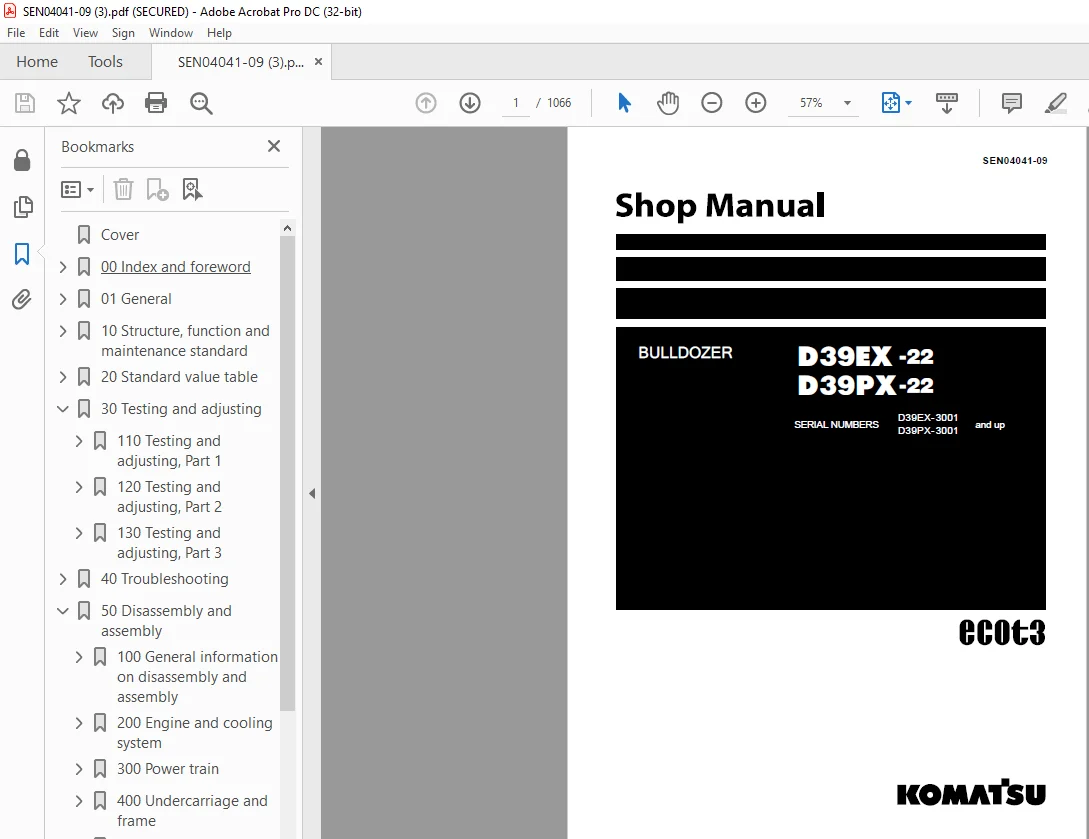
Komatsu Bulldozer D39EX-22 D39PX-22 Shop Manual SEN04041-09 PDF
$37.95
Komatsu Bulldozer D39EX-22 D39PX-22 Shop Manual SEN04041-09 – PDF DOWNLOAD
SERIAL NUMBERS D39EX-3001
D39PX-3001 and up
Instant PDF Download
Available immediately
Save to Your Device
Download & keep forever
Antivirus Scanned
100% virus-free
Trusted Worldwide
175,000+ customers
Description
Komatsu Bulldozer D39EX-22 D39PX-22 Shop Manual SEN04041-09 – PDF DOWNLOAD
FILE DETAILS:
Komatsu Bulldozer D39EX-22 D39PX-22 Shop Manual SEN04041-09 – PDF DOWNLOAD
Language : English
Pages :1066
Downloadable : Yes
File Type : PDF
DESCRIPTION:
Komatsu Bulldozer D39EX-22 D39PX-22 Shop Manual SEN04041-09 – PDF DOWNLOAD
SERIAL NUMBERS D39EX-3001
D39PX-3001 and up
1. General precautions k
Mistakes in operation are extremely dangerous. Read the Operation and Maintenance Manual carefully before operating the machine. In addition, read this manual and understand its contents before starting the work.
1) Before carrying out any greasing or repairs, read all the safety labels stuck to the machine. For the locations of the safety labels and detailed explanation of precautions, see the Operation and Maintenance Manual.
2) Decide a place in the repair workshop to keep tools and removed parts. Always keep the tools and parts in their correct places. Always keep the work area clean and make sure that there is no dirt, water, or oil on the floor. Smoke only in the areas provided for smoking. Never smoke while working.
3) When carrying out any operation, always wear safety shoes and helmet. Do not wear loose work clothes, or clothes with buttons missing. q Always wear safety glasses when hitting parts with a hammer. q Always wear safety glasses when grinding parts with a grinder, etc.
4) When carrying out any operation with 2 or more workers, always agree on the operating procedure before starting. Always inform your fellow workers before starting any step of the operation. Before starting work, hang UNDER REPAIR warning signs in the operator’s compartment.
5) Only the approved personnel can do the work in a closed environment or in a prohibited area.
6) Only qualified workers must carry out work and operation which require license or qualification.
7) Keep all tools in good condition, learn the correct way to use them, and use the proper ones of them. Before starting work, thoroughly check the tools, machine, forklift, service car, etc.
8) If welding repairs are needed, always have a trained and experienced welder carry out the work. When carrying out welding work, always wear welding gloves, apron, shielding goggles, cap and other clothes suited for welding work.
9) Before starting work, warm up your body thoroughly to start work under good condition.
10) Avoid continuing work for long hours and take rests at proper intervals to keep your body in good condition. Take rests in specified safe places.
11) When you work in high places, use a platform. 12) Before you start the work, use the personal fall-arrest equipment to prevent falling. There is a danger of personal accident that you fall by slipping.
13) Always do the work correctly. If you find the unsafe behavior of co-worker, give him/her a notice and stop it.
14) Because there is a danger that you are caught, be very careful when the work is done in dangerous areas such as: when you go in the range where the lifted load possibly falls, or when you stand directly in front of tire, or when you are near the sliding parts.
15) When you handle chemical materials (such as nitrogen gas), see the MSDS (safety data sheet) and local guidelines, and get the important information (such as a safe handling method). Also, put on applicable protective equipment (such as protective goggles, gloves, and masks).
16) If necessary, cut out all the power sources (electricity, oil pressure, compressed air, etc.) before you start the work. If the machine has a lock mechanism, set it to the LOCK position and install the warning tag in a position where it is easy to see. Do not release the lock until the work is completed.
2. Preparations for work
1) Before adding oil or making any repairs, park the machine on a hard and level ground, and apply the parking brake and block the wheels or tracks to prevent the machine from moving.
2) Before starting work, lower the work equipment (blade, ripper, bucket, etc.) to the ground. If this is not possible, insert the lock pin or use blocks to prevent the work equipment from falling. In addition, be sure to lock all the control levers and hang warning signs on them.
3) When disassembling or assembling, support the machine with blocks, jacks, or stands before starting work.
4) Remove all mud and oil from the steps or other places used to get on and off the machine. Always use the handrails, ladders or steps when getting on or off the machine. Never jump on or off the machine. If it is impossible to use the handrails, ladders or steps, use a stand to provide safe footing.
TABLE OF CONTENTS:
Komatsu Bulldozer D39EX-22 D39PX-22 Shop Manual SEN04041-09 – PDF DOWNLOAD
SERIAL NUMBERS D39EX-3001
D39PX-3001 and up
Cover 1
00 Index and foreword 3
100 Index 3
Composition of shop manual 4
Table of contents 6
200 Foreword and general information 15
Safety notice 16
How to read the shop manual 21
Explanation of terms for maintenance standard 23
Handling of electric equipment and hydraulic component 25
Handling of connectors newly used for engines 34
How to read electric wire code 37
Precautions when carrying out operation 40
Method of disassembling and connecting push-pull type coupler 43
Standard tightening torque table 46
Conversion table 50
01 General 57
100 Specification and technical data 57
Specification dimensional drawing 58
Specifications 59
Weight table 63
Table of fuel, coolant and lubricants 65
10 Structure, function and maintenance standard 67
100 Engine and cooling system 67
Engine system parts 68
Cooling system 69
Cooling fan pump 70
Cooling fan motor 71
Oil cooler bypass valve 76
200 Power train 81
Power train 82
Power train system 83
Damper 84
HST hydraulic equipment arrangement diagram 85
Steering and brake control 86
Solenoid valve 88
Final drive 95
HST pump 98
HST motor 110
Charge pump 120
300 Undercarriage and frame 123
Main frame 124
Track frame and idler cushion 126
Idler 128
Track roller 130
Carrier roller 132
Sprocket 134
Track shoe 136
410 Hydraulic system, Part 1 143
Arrangement of hydraulic equipment for work equipment 144
Work equipment control 146
Hydraulic tank and filter 148
Work equipment and fan pump 150
Control valve 158
CLSS 170
Functions and operation of each valve 173
420 Hydraulic system, Part 2 183
Blade PPC valve 184
Accumulator 190
500 Work equipment 193
Work equipment 194
Cutting edge and end bit 198
Ripper 199
Work equipment cylinder 200
Piston valve 203
600 Cab and its attachments 205
ROPS cab 206
Cab mount 207
Canopy mount 208
Air conditioner 209
700 Electrical system 213
Monitor system 214
Engine control 216
Engine control system 217
Cooling control system 218
HST control system 220
Parking brake control system 226
KOMTRAX system 228
Component equipment of system 232
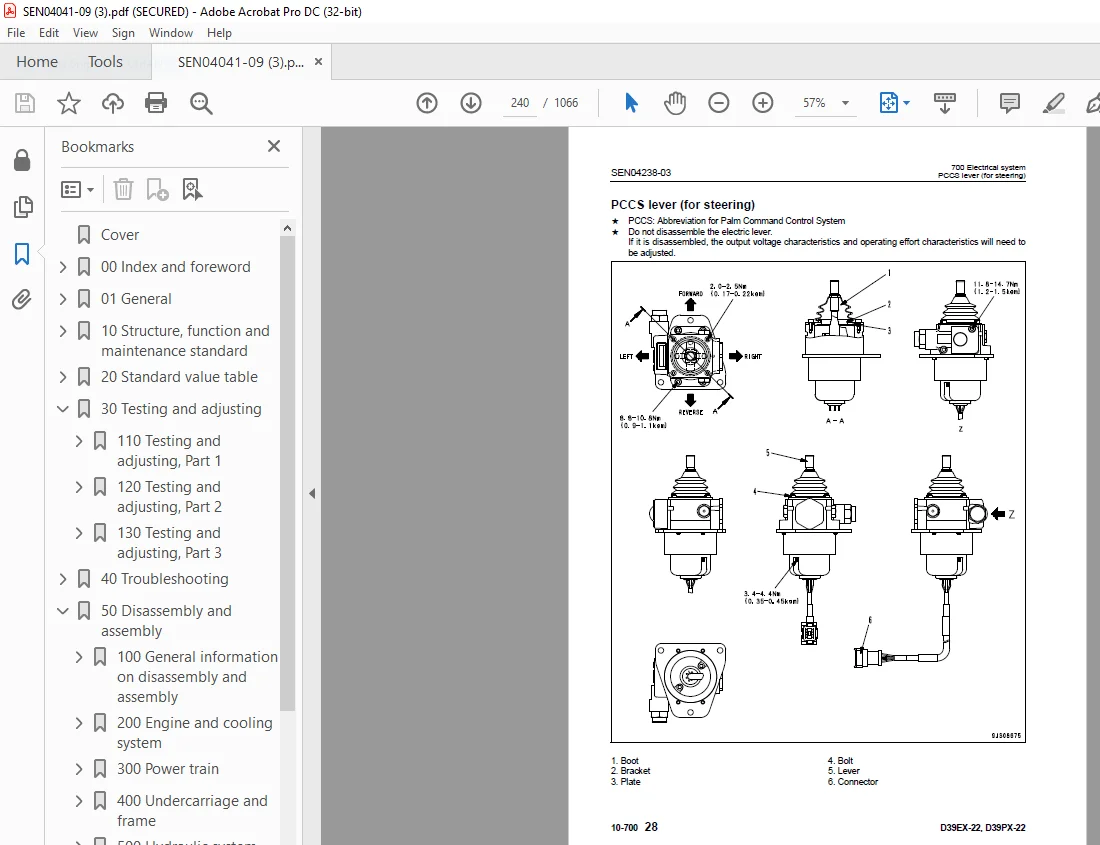
PCCS lever (for steering) 240
Sensor 243
20 Standard value table 255
100 Standard service value table 255
Standard service value table for engine 256
Standard service value table for chassis 257
30 Testing and adjusting 265
110 Testing and adjusting, Part 1 265
Precautions before work 267
Tools for testing, adjusting, and troubleshooting 268
Sketches of special tools 271
Measuring engine speed 272
Measuring intake air pressure (boost pressure) 273
Measuring exhaust gas color (boost pressure) 275
Adjusting valve clearance 276
Measuring compression pressure 278
Measuring blow-by pressure 281
Testing engine oil pressure 283
Handling fuel system equipment 284
Releasing residual pressure in fuel system 284
Bleeding air from fuel circuit 285
Measuring fuel pressure 286
Measuring fuel discharge, return and leakage 288
Testing leakage in fuel system 292
Measurement of fan circuit pressure and fan speed 293
Adjustment of fan speed sensor 294
Handling reduced cylinder mode operation 295
Handling no-injection cranking operation 295
Handling controller voltage circuit 296
Check of muffler and muffler stack for looseness and damage 297
Check of muffler function 297
Check of installed condition of cylinder head and manifolds 298
Check of engine piping for damage and looseness 298
Replacing alternator belt 299
120 Testing and adjusting, Part 2 301
Adjusting decelerator pedal 302
Testing and adjusting HST oil pressure 304
Measuring solenoid valve outlet pressure 309
Testing travel deviation 312
Adjusting parking brake lever 313
Simple brake performance test procedure 315
Adjusting brake pedal 316
Method of releasing parking brake (Procedure for emergency escape) 318
Testing and adjusting idler clearance 320
Testing and adjusting track shoe tension 321
Testing work equipment pressure 322
Testing work equipment PPC valve 324
Adjusting play of work equipment PPC valve 326
Adjusting work equipment lock lever 327
Testing internal leakage of work equipment cylinder 328
Releasing residual pressure in hydraulic circuit 330
Bleeding air from hydraulic circuit 331
Adjusting play of blade center ball 332
Procedure for testing diodes 333
Preparation work for troubleshooting for electrical system 334
How to start operation of KOMTRAX terminal 338
Lamp display of KOMTRAX terminal 341
130 Testing and adjusting, Part 3 345
Special functions of monitor panel (EMMS) 346
Items to be adjusted when electric/hydraulic devices are adjusted/replaced 408
Adjustment procedure after replacement of HST controller 409
Adjustment procedure after replacement of monitor panel 411
Pm-clinic 412
40 Troubleshooting 423
100 Failure code table and fuse locations 423
Precautions before work 424
Failure code table 425
Before carrying out troubleshooting for electrical system (E-mode) 431
200 General information on troubleshooting 435
Points to remember when troubleshooting 436
Sequence of events in troubleshooting 437
Testing before troubleshooting 438
Classification and procedures of troubleshooting 439
Information contained in troubleshooting table 442
Connection table for connector pin numbers 444
T- branch box and T- branch adapter table 480
310 Troubleshooting by failure code (Display of code), Part 1 485
Failure code [6091NX] HST charge filter element: Clogging 487
Failure code [AA10NX] Air cleaner: Clogging 488
Failure code [AB00MA] Alternator: Malfunction 490
Failure code [B@BAZG] Engine oil: Lowering of oil pressure 491
Failure code [B@BCNS] Coolant: Overheat 492
Failure code [B@CRNS] HST oil: Overheating 493
Failure code [B@CRZG] HST oil: Lowering of oil pressure 494
Failure code [CA111] Engine controller: Abnormality in controller 495
Failure code [CA115] Abnormal engine Ne and Bkup speed sensors: Abnormal speed sensor signal 495
Failure code [CA122] Charge pressure sensor tool high: Excessively high voltage detected 496
Failure code [CA123] Charge pressure sensor too low: Excessively low voltage detected 498
Failure code [CA131] Decelerator pedal sensor tool high: Excessively high voltage detected 500
Failure code [CA132] Decelerator pedal sensor too low: Excessively low voltage detected 502
Failure code [CA144] Coolant temperature sensor too high: Excessively high voltage detected 504
Failure code [CA145] Coolant temperature sensor too low: Excessively low voltage detected 506
Failure code [CA153] Charge air temperature sensor too high: Excessively high voltage detected 508
Failure code [CA154] Charge temperature sensor too low: Excessively low voltage detected 510
Failure code [CA187] Sensor power source 2 too low: Excessively low voltage detected 512
Failure code [CA221] Atmospheric pressure sensor too high: Excessively high voltage detected 514
Failure code [CA222] Atmospheric pressure sensor too low: Excessively low voltage detected 516
Failure code [CA227] Sensor power source 2 too high: Excessively high voltage detected 518
Failure code [CA234] Engine over speed: Excessively high speed 520
Failure code [CA238] Abnormal power source for Ne speed sensor: Excessively low voltage detected 521
Failure code [CA271] IMV/PCV1 short circuit: Short circuit 522
Failure code [CA272] IMV/PCV1 disconnection: Disconnection 524
320 Troubleshooting by failure code (Display of code), Part 2 527
Failure code [CA322] Injector No 1 system disconnection or short circuit: disconnection, short circuit 530
Failure code [CA324] Injector No 3 system disconnection or short circuit: disconnection, short circuit 532
Failure code [CA331] Injector No 2 system disconnection or short circuit: disconnection, short circuit 534
Failure code [CA332] Injector No 4 system disconnection or short circuit: disconnection, short circuit 536
Failure code [CA342] Engine controller data matching error: matching error 538
Failure code [CA351] Injector drive circuit abnormality: Abnormal circuit 540
Failure code [CA352] Sensor power source 1 too low: Excessively low voltage detected 542
Failure code [CA386] Sensor power source 1 too high: Excessively high voltage detected 544
Failure code [CA428] Water in fuel sensor too high: Excessively high voltage detected 546
Failure code [CA429] Water in fuel sensor too low: Excessively low voltage detected 548
Failure code [CA435] Abnormal engine oil pressure switch: Abnormal signal circuit 550
Failure code [CA441] Power source voltage too low: Excessively low voltage detected 552
Failure code [CA442] Power source voltage too high: Excessively high voltage has occurred in the controller power source circuit 554
Failure code [CA449] Common rail pressure too high (2): Excessively high pressure trouble occurred 556
Failure code [CA451] Common rail pressure sensor too high: Excessively high voltage detected 558
Failure code [CA452] Common rail pressure sensor too low: Excessively low voltage detected 560
Failure code [CA488] Charge temperature too high and torque derated: Exceeded upper control limit of temperature 562
Failure code [CA553] Common rail pressure too high (1): Excessively high pressure detected 563
Failure code [CA559] Loss of pressure feed from supply pump (1): Loss of pressure feed detected 564
Failure code [CA689] Abnormal engine Ne speed sensor: Abnormal signal 566
Failure code [CA731] Abnormal engine Bkup speed sensor phase: Abnormal phase 568
Failure code [CA757] Loss of all engine controller data: Loss of all data 570
Failure code [CA778] Abnormal engine Bkup speed sensor: Abnormal Bkup signal 572
Failure code [CA1633] Abnormal KOMNET: Abnormal communication 574
Failure code [CA2185] Decelerator pedal sensor power source too high: Excessively high voltage detected 576
Failure code [CA2186] Decelerator pedal sensor power source too low: Excessively low voltage detected 578
Failure code [CA2249] Loss of pressure feed from supply pump (2): Loss of pressure feed detected 580
Failure code [CA2311] Abnormal IMV solenoid: Abnormal resistance 582
Failure code [CA2555] Air intake heater relay disconnection: Disconnection 584
Failure code [CA2556] Air intake heater relay short circuit: Short circuit 586
330 Troubleshooting by failure code (Display of code), Part 3 589
Failure code [D130KA] Neutral safety relay: Disconnection 592
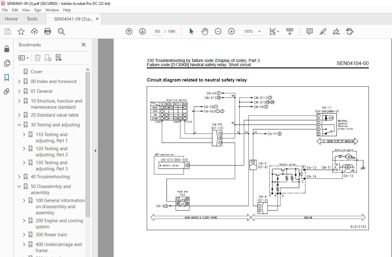
Failure code [D130KB] Neutral safety relay: Short circuit 594
Failure code [DAFRKR] CAN communication (Monitor panel – HST controller): Defective communication (Abnormality in objective component system) 596
Failure code [DAFRMC] CAN communication (Monitor panel – ENGINE controller): Defective communication (Abnormality in objective component system) 599
Failure code [DAJ000] HST controller: Memory error 602
Failure code [DAJ0KK] HST controller: Lowing of source voltage 604
Failure code [DAJ0KQ] HST controller: Machine code error 606
Failure code [DAJ0KT] HST controller: Memory error 607
Failure code [DAJ5KK] HST controller sensor 5 V power supply No1: Lowing of source voltage/Input 608
Failure code [DAJ6KK] HST controller sensor 5 V power supply No2: Lowing of source voltage/Input 610
Failure code [DAJRKR] CAN communication (HST controller – Monitor panel): Defective communication (Abnormality in objective component system) 612
Failure code [DB2RKR] CAN communication (HST controller – Engine controller): Defective communication (Abnormality in objective component system) 615
Failure code [DD12KA] Shift up switch: Disconnection 618
Failure code [DD12KB] Shift up switch: Short circuit 620
Failure code [DD13KA] Shift down switch: Disconnection 622
Failure code [DD13KB] Shift down switch: Short circuit 624
Failure code [DD14KB] Travel lock limit switch 1: Short circuit 626
Failure code [DD1NL4] Fan rotation selector switch: Disagreement of ON, OFF Signals 628
Failure code [DDDCKB] Reverse travel speed switch: Short circuit 630
Failure code [DDP6KA] Brake oil pressure sensor: Disconnection 632
Failure code [DDP6KB] Brake oil pressure sensor: Short circuit 634
Failure code [DDP6MA] Brake oil pressure sensor: Malfunction 636
Failure code [DDQ2KA] Travel lock limit switch 1: Disconnection 638
Failure code [DDT0L4] Shift mode switch: Disagreement of ON/ OFF Signals 640
Failure code [DDU1FS] Travel lock limit switches 1 and 2: Fixing 642
Failure code [DDU1KA] Travel lock limit switch 2: Disconnection 644
Failure code [DDU1KY] Travel lock limit switch 2: Short circuit with power supply line 646
Failure code [DGS1KA] HST oil temperature sensor: Disconnection 648
Failure code [DGS1KX] HST oil temperature sensor: Out of Input signal range 650
340 Troubleshooting by failure code (Display of code), Part 4 653
Failure code [DHH5KA] Left HST pump pressure sensor: Disconnection 656
Failure code [DHH5KB] Left HST pump pressure sensor: Short circuit 658
Failure code [DHH6KA] Right HST pump pressure sensor: Disconnection 660
Failure code [DHH6KB] Right HST pump pressure sensor: Short circuit 662
Failure code [DK10KA] Fuel dial sensor: Disconnection 664
Failure code [DK10KB] Fuel dial sensor: Short circuit 666
Failure code [DK30KA] Steering angle sensor 1: Disconnection 668
Failure code [DK30KB] Steering angle sensor 1: Short circuit 670
Failure code [DK30KX] Steering angle sensor: Out of input signal range 672
Failure code [DK30KZ] Steering angle sensor: Disconnection or short circuit 673
Failure code [DK30L8] Steering angle sensor: Disagreement of analog signals 674
Failure code [DK31KA] Steering angle sensor 2: Disconnection 676
Failure code [DK31KB] Steering angle sensor 2: Short circuit 678
Failure code [DK40KA] Brake pedal sensor: Disconnection 680
Failure code [DK40KB] Brake pedal sensor: Short circuit 682
Failure code [DK55KX] Directional potentiometer: Out of input signal range 684
Failure code [DK55KZ] Directional potentiometer: Disconnection or short circuit 685
Failure code [DK55L8] Directional potentiometer: Disagreement of analog signals 686
Failure code [DK56KA] Directional potentiometer 1: Disconnection 688
Failure code [DK56KB] Directional potentiometer 1: Short circuit 690
Failure code [DK57KA] Directional potentiometer 2: Disconnection 692
Failure code [DK57KB] Directional potentiometer 2: Short circuit 694
Failure code [DLM0KX] HST motor speed sensors: Out of input signal range 696
Failure code [DLM1KA] Left HST motor speed sensor: Disconnection 698
Failure code [DLM1KB] Left HST motor speed sensor: Short circuit 700
Failure code [DLM1MA] Left HST motor speed sensor: Malfunction 702
Failure code [DLM2KA] Right HST motor speed sensor: Disconnection 704
Failure code [DLM2KB] Right HST motor speed sensor: Short circuit 706
Failure code [DLM2MA] Right HST motor speed sensor: Malfunction 708
Failure code [DLM3KA] Fan speed sensor: Disconnection 710
Failure code [DLM3KB] Fan speed sensor: Short circuit 712
350 Troubleshooting by failure code (Display of code), Part 5 715
Failure code [DN21FS] Brake pedal and proximity switch: Fixing 718
Failure code [DV00KB] Caution buzzer: Short circuit 720
Failure code [DV20KB] Back alarm buzzer: Short circuit 721
Failure code [DW4BKA] Parking brake solenoid valve: Disconnection 722
Failure code [DW4BKB] Parking brake solenoid valve: Short circuit 724
Failure code [DW4BKY] Parking brake solenoid valve: Short circuit with power supply line 726
Failure code [DW7BKA] Fan reverse solenoid valve: Disconnection 728
Failure code [DW7BKB] Fan reverse solenoid valve: Short circuit 730
Failure code [DW7BKY] Fan reverse solenoid valve: Short circuit with power supply line 731
Failure code [DW7EKA] Slow brake solenoid valve: Disconnection 732
Failure code [DW7EKB] Slow brake solenoid valve: Short circuit 736
Failure code [DW7EKY] Slow brake solenoid valve: Short circuit with power supply line 738
Failure code [DWN5KA] Fan EPC solenoid valve: Disconnection 740
Failure code [DWN5KB] Fan EPC solenoid valve: Short circuit 742
Failure code [DWN5KY] Fan EPC solenoid valve: Short circuit with power supply line 744
Failure code [DXA4KA] LF HST pump EPC solenoid valve: Disconnection 746
Failure code [DXA4KB] LF HST pump EPC solenoid valve: Short circuit 748
Failure code [DXA4KY] LF HST pump EPC solenoid valve: Short circuit with power supply line 750
Failure code [DXA5KA] LR HST pump EPC solenoid valve: Disconnection 752
Failure code [DXA5KB] LR HST pump EPC solenoid valve: Short circuit 754
Failure code [DXA5KY] LR HST pump EPC solenoid valve: Short circuit with power supply line 756
Failure code [DXA6KA] RF HST pump EPC solenoid valve: Disconnection 758
Failure code [DXA6KB] RF HST pump EPC solenoid valve: Short circuit 760
Failure code [DXA6KY] RF HST pump EPC solenoid valve: Short circuit with power supply line 761
Failure code [DXA7KA] RR HST pump EPC solenoid valve: Disconnection 762
Failure code [DXA7KB] RR HST pump EPC solenoid valve: Short circuit 764
Failure code [DXA7KY] RR HST pump EPC solenoid valve: Short circuit with power supply line 766
Failure code [DXK1KA] Left HST motor EPC solenoid valve: Disconnection 768
Failure code [DXK1KB] Left HST motor EPC solenoid valve: Short circuit 769
Failure code [DXK1KY] Left HST motor EPC solenoid valve: Short circuit with power supply line 770
Failure code [DXK2KA] Right HST motor EPC solenoid valve: Disconnection 771
Failure code [DXK2KB] Right HST motor EPC solenoid valve: Short circuit 772
Failure code [DXK2KY] Right HST motor EPC solenoid valve: Short circuit with power supply line 773
400 Troubleshooting of electrical system (E-mode) 775
E-1 Engine does not start (Starting motor does not rotate) 778
E-2 Engine is not preheated 781
E-3 When starting switch is turned ON, any item does not light up 784
E-4 Charge level caution flashes while engine is running 786
E-5 Emergency warning items flash while engine is running 788
E-6 Preheating pilot lamp does not light up during preheating operation 794
E-7 The coolant temperature gauge does not indicate correctly 796
E-8 The HST oil temperature gauge does not indicate correctly 797
E-9 Fuel level gauge does not indicate properly 798
E-10 Gear speed, set travel speed, and shift mode indicator does not display normally 800
E-11 Multi-information unit does not display normally 800
E-12 Caution lamp does not flash or does not go off 801
E-13 Caution buzzer does not sound or does not stop 802
E-14 Reverse travel speed setting switch does not function 804
E-15 Shift mode switch does not function 806
E-16 Buzzer cancel switch does not function 808
E-17 Information switch does not function 810
E-18 The fan cleaning does not operate or cannot be reset 812
E-19 Backup alarm does not sound 814
E-20 The horn does not sound or does not stop 815
E-21 Work equipment does not move 816
E-22 Headlamp or rear lamp does not light up 818
E-23 Foot heater does not operate 821
E-24 Air conditioner does not operate 824
E-25 Windshield wiper and window washer do not operate 829
E-26 KOMTRAX system does not operate normally 842
500 Troubleshooting of hydraulic and mechanical system (H-mode) 847
Information in troubleshooting table 849
H-1 Right and left travel systems do not operate forward and in reverse (No travel systems operate) 850
H-2 Right or left travel system does not operate forward and in reverse (Only right or left travel system does not operate) 852
H-3 Right or left travel system does not operate forward or in reverse (Only 1 system does not operate) 853
H-4 Speed or power of travel is low 854
H-5 Gear is not shifted 855
H-6 Large shocks are made when machine starts and stops travel 856
H-7 Machine deviates largely during travel 857
H-8 Hydraulic drift of travel is large 858
H-9 Engine stalls or engine speed lowers extremely during travel 859
H-10 Abnormal sound comes out from around HST pump and motor 860
H-11 Work equipment dose not operate at all 861
H-12 Speed or power of whole work equipment is low 862
H-13 Speed or power of lifting blade is low 863
H-14 Speed or power of tilting blade is low 864
H-15 Speed or power of angling blade is low 865
H-16 Time lag in lifting blade is large 866
H-17 Hydraulic drift of lifting blade is large 866
H-18 Hydraulic drift of tilting blade is large 866
H-19 Abnormal sound comes out from around work equipment pump and control valve 867
H-20 HST oil temperature (Hydraulic oil temperature) rises too high 868
H-21 Fan speed is abnormal (High, low, or 0 rpm) 870
H-22 Abnormal sound is heard from around fan 871
600 Troubleshooting of engine (S-mode) 873
Method of using troubleshooting charts 875
S-1 Starting performance is poor 878
S-2 Engine does not start 879
S-3 Engine does not pick up smoothly 882
S-4 Engine stops during operations 883
S-5 Engine does not rotate smoothly 884
S-6 Engine lacks output (or lacks power) 885
S-7 Exhaust smoke is black (imcomplete combustion) 886
S-8 Oil consumption is excessive (or exhaust smoke is blue) 887
S-9 Oil becomes contaminated quickly 888
S-10 Fuel consumption is excessive 889
S-11 Oil is in coolant (or coolant spurts back, or coolant level goes down) 890
S-12 Oil pressure drops 891
S-13 Oil level rises (water, fuel in oil) 892
S-14 Coolant temperature becomes too high (overheating) 893
S-15 Abnormal noise is made 894
S-16 Vibration is excessive 895
50 Disassembly and assembly 897
100 General information on disassembly and assembly 897
Precautions before work 898
How to read this manual 899
Coating materials list 901
Special tools list 904
Sketches of special tools 907
200 Engine and cooling system 911
Removal and installation of fuel supply pump assembly 912
Removal and installation of fuel injector assembly 916
Removal and installation of cylinder head assembly 924
Removal and installation of engine and HST pump assembly 937
Removal and installation of engine front seal assembly 940
Removal and installation of engine rear seal assembly 942
Removal and installation of front guard assembly 946
Removal and installation of radiator assembly 948
Removal and installation of hydraulic oil cooler assembly 950
Removal and installation of aftercooler assembly 952
Removal and installation of cooling fan and motor assembly 954
Removal and installation of cooling fan drive motor assembly1 956
Removal and installation of fuel tank assembly 958
300 Power train 961
Removal and installation of HST pump assembly 962
Removal and installation of HST motor and final drive assembly 964
Disassembly and assembly of final drive assembly 966
400 Undercarriage and frame 977
Spreading and installation of track shoe assembly 978
Removal and installation of idler and recoil spring assembly 980
Disassembly and assembly of idler assembly 981
Disassembly and assembly of recoil spring assembly 984
Disassembly and assembly of track roller assembly 988
Disassembly and assembly of carrier roller assembly 992
500 Hydraulic system 997
Removal and installation of hydraulic tank assembly 998
Removal and installation of control valve assembly1000
Disassembly and assembly of control valve assembly1001
Disassembly and assembly of hydraulic cylinder assembly1003
600 Work equipment1009
Removal and installation of work equipment assembly1010
700 Cab and its attachments1015
Removal and installation of ROPS canopy and operator seat frame assembly1016
Removal and installation of ROPS cab and operator seat frame assembly1019
Removal and installation of operator’s cab glass (Stuck glass)1024
800 Electrical system1031
Removal and installation of HST controller assembly1032
Removal and installation of KOMTRAX terminal assembly1033
90 Diagrams and drawings1035
100 Hydraulic diagrams and drawings1035
Work equipment hydraulic circuit diagram1037
200 Electrical diagrams and drawings1041
Electrical circuit diagram1043
Cab electrical circuit diagram1057
Air conditioner circuit diagram1061
Connector list and stereogram1063
00 Index and foreword 3
100 Index 3
Composition of shop manual 4
Table of contents 6
200 Foreword and general information 15
Safety notice 16
How to read the shop manual 21
Explanation of terms for maintenance standard 23
Handling of electric equipment and hydraulic component 25
Handling of connectors newly used for engines 34
How to read electric wire code 37
Precautions when carrying out operation 40
Method of disassembling and connecting push-pull type coupler 43
Standard tightening torque table 46
Conversion table 50
01 General 57
100 Specification and technical data 57
Specification dimensional drawing 58
Specifications 59
Weight table 63
Table of fuel, coolant and lubricants 65
10 Structure, function and maintenance standard 67
100 Engine and cooling system 67
Engine system parts 68
Cooling system 69
Cooling fan pump 70
Cooling fan motor 71
Oil cooler bypass valve 76
200 Power train 81
Power train 82
Power train system 83
Damper 84
HST hydraulic equipment arrangement diagram 85
Steering and brake control 86
Solenoid valve 88
Final drive 95
HST pump 98
HST motor 110
Charge pump 120
300 Undercarriage and frame 123
Main frame 124
Track frame and idler cushion 126
Idler 128
Track roller 130
Carrier roller 132
Sprocket 134
Track shoe 136
410 Hydraulic system, Part 1 143
Arrangement of hydraulic equipment for work equipment 144
Work equipment control 146
Hydraulic tank and filter 148
Work equipment and fan pump 150
Control valve 158
CLSS 170
Functions and operation of each valve 173
420 Hydraulic system, Part 2 183
Blade PPC valve 184
Accumulator 190
500 Work equipment 193
Work equipment 194
Cutting edge and end bit 198
Ripper 199
Work equipment cylinder 200
Piston valve 203
600 Cab and its attachments 205
ROPS cab 206
Cab mount 207
Canopy mount 208
Air conditioner 209
700 Electrical system 213
Monitor system 214
Engine control 216
Engine control system 217
Cooling control system 218
HST control system 220
Parking brake control system 226
KOMTRAX system 228
Component equipment of system 232
PCCS lever (for steering) 240
Sensor 243
20 Standard value table 255
100 Standard service value table 255
Standard service value table for engine 256
Standard service value table for chassis 257
30 Testing and adjusting 265
110 Testing and adjusting, Part 1 265
Precautions before work 267
Tools for testing, adjusting, and troubleshooting 268
Sketches of special tools 271
Measuring engine speed 272
Measuring intake air pressure (boost pressure) 273
Measuring exhaust gas color (boost pressure) 275
Adjusting valve clearance 276
Measuring compression pressure 278
Measuring blow-by pressure 281
Testing engine oil pressure 283
Handling fuel system equipment 284
Releasing residual pressure in fuel system 284
Bleeding air from fuel circuit 285
Measuring fuel pressure 286
Measuring fuel discharge, return and leakage 288
Testing leakage in fuel system 292
Measurement of fan circuit pressure and fan speed 293
Adjustment of fan speed sensor 294
Handling reduced cylinder mode operation 295
Handling no-injection cranking operation 295
Handling controller voltage circuit 296
Check of muffler and muffler stack for looseness and damage 297
Check of muffler function 297
Check of installed condition of cylinder head and manifolds 298
Check of engine piping for damage and looseness 298
Replacing alternator belt 299
120 Testing and adjusting, Part 2 301
Adjusting decelerator pedal 302
Testing and adjusting HST oil pressure 304
Measuring solenoid valve outlet pressure 309
Testing travel deviation 312
Adjusting parking brake lever 313
Simple brake performance test procedure 315
Adjusting brake pedal 316
Method of releasing parking brake (Procedure for emergency escape) 318
Testing and adjusting idler clearance 320
Testing and adjusting track shoe tension 321
Testing work equipment pressure 322
Testing work equipment PPC valve 324
Adjusting play of work equipment PPC valve 326
Adjusting work equipment lock lever 327
Testing internal leakage of work equipment cylinder 328
Releasing residual pressure in hydraulic circuit 330
Bleeding air from hydraulic circuit 331
Adjusting play of blade center ball 332
Procedure for testing diodes 333
Preparation work for troubleshooting for electrical system 334
How to start operation of KOMTRAX terminal 338
Lamp display of KOMTRAX terminal 341
130 Testing and adjusting, Part 3 345
Special functions of monitor panel (EMMS) 346
Items to be adjusted when electric/hydraulic devices are adjusted/replaced 408
Adjustment procedure after replacement of HST controller 409
Adjustment procedure after replacement of monitor panel 411
Pm-clinic 412
40 Troubleshooting 423
100 Failure code table and fuse locations 423
Precautions before work 424
Failure code table 425
Before carrying out troubleshooting for electrical system (E-mode) 431
200 General information on troubleshooting 435
Points to remember when troubleshooting 436
Sequence of events in troubleshooting 437
Testing before troubleshooting 438
Classification and procedures of troubleshooting 439
Information contained in troubleshooting table 442
Connection table for connector pin numbers 444
T- branch box and T- branch adapter table 480
310 Troubleshooting by failure code (Display of code), Part 1 485
Failure code [6091NX] HST charge filter element: Clogging 487
Failure code [AA10NX] Air cleaner: Clogging 488
Failure code [AB00MA] Alternator: Malfunction 490
Failure code [B@BAZG] Engine oil: Lowering of oil pressure 491
Failure code [B@BCNS] Coolant: Overheat 492
Failure code [B@CRNS] HST oil: Overheating 493
Failure code [B@CRZG] HST oil: Lowering of oil pressure 494
Failure code [CA111] Engine controller: Abnormality in controller 495
Failure code [CA115] Abnormal engine Ne and Bkup speed sensors: Abnormal speed sensor signal 495
Failure code [CA122] Charge pressure sensor tool high: Excessively high voltage detected 496
Failure code [CA123] Charge pressure sensor too low: Excessively low voltage detected 498
Failure code [CA131] Decelerator pedal sensor tool high: Excessively high voltage detected 500
Failure code [CA132] Decelerator pedal sensor too low: Excessively low voltage detected 502
Failure code [CA144] Coolant temperature sensor too high: Excessively high voltage detected 504
Failure code [CA145] Coolant temperature sensor too low: Excessively low voltage detected 506
Failure code [CA153] Charge air temperature sensor too high: Excessively high voltage detected 508
Failure code [CA154] Charge temperature sensor too low: Excessively low voltage detected 510
Failure code [CA187] Sensor power source 2 too low: Excessively low voltage detected 512
Failure code [CA221] Atmospheric pressure sensor too high: Excessively high voltage detected 514
Failure code [CA222] Atmospheric pressure sensor too low: Excessively low voltage detected 516
Failure code [CA227] Sensor power source 2 too high: Excessively high voltage detected 518
Failure code [CA234] Engine over speed: Excessively high speed 520
Failure code [CA238] Abnormal power source for Ne speed sensor: Excessively low voltage detected 521
Failure code [CA271] IMV/PCV1 short circuit: Short circuit 522
Failure code [CA272] IMV/PCV1 disconnection: Disconnection 524
320 Troubleshooting by failure code (Display of code), Part 2 527
Failure code [CA322] Injector No 1 system disconnection or short circuit: disconnection, short circuit 530
Failure code [CA324] Injector No 3 system disconnection or short circuit: disconnection, short circuit 532
Failure code [CA331] Injector No 2 system disconnection or short circuit: disconnection, short circuit 534
Failure code [CA332] Injector No 4 system disconnection or short circuit: disconnection, short circuit 536
Failure code [CA342] Engine controller data matching error: matching error 538
Failure code [CA351] Injector drive circuit abnormality: Abnormal circuit 540
Failure code [CA352] Sensor power source 1 too low: Excessively low voltage detected 542
Failure code [CA386] Sensor power source 1 too high: Excessively high voltage detected 544
Failure code [CA428] Water in fuel sensor too high: Excessively high voltage detected 546
Failure code [CA429] Water in fuel sensor too low: Excessively low voltage detected 548
Failure code [CA435] Abnormal engine oil pressure switch: Abnormal signal circuit 550
Failure code [CA441] Power source voltage too low: Excessively low voltage detected 552
Failure code [CA442] Power source voltage too high: Excessively high voltage has occurred in the controller power source circuit 554
Failure code [CA449] Common rail pressure too high (2): Excessively high pressure trouble occurred 556
Failure code [CA451] Common rail pressure sensor too high: Excessively high voltage detected 558
Failure code [CA452] Common rail pressure sensor too low: Excessively low voltage detected 560
Failure code [CA488] Charge temperature too high and torque derated: Exceeded upper control limit of temperature 562
Failure code [CA553] Common rail pressure too high (1): Excessively high pressure detected 563
Failure code [CA559] Loss of pressure feed from supply pump (1): Loss of pressure feed detected 564
Failure code [CA689] Abnormal engine Ne speed sensor: Abnormal signal 566
Failure code [CA731] Abnormal engine Bkup speed sensor phase: Abnormal phase 568
Failure code [CA757] Loss of all engine controller data: Loss of all data 570
Failure code [CA778] Abnormal engine Bkup speed sensor: Abnormal Bkup signal 572
Failure code [CA1633] Abnormal KOMNET: Abnormal communication 574
Failure code [CA2185] Decelerator pedal sensor power source too high: Excessively high voltage detected 576
Failure code [CA2186] Decelerator pedal sensor power source too low: Excessively low voltage detected 578
Failure code [CA2249] Loss of pressure feed from supply pump (2): Loss of pressure feed detected 580
Failure code [CA2311] Abnormal IMV solenoid: Abnormal resistance 582
Failure code [CA2555] Air intake heater relay disconnection: Disconnection 584
Failure code [CA2556] Air intake heater relay short circuit: Short circuit 586
330 Troubleshooting by failure code (Display of code), Part 3 589
Failure code [D130KA] Neutral safety relay: Disconnection 592
Failure code [D130KB] Neutral safety relay: Short circuit 594
Failure code [DAFRKR] CAN communication (Monitor panel – HST controller): Defective communication (Abnormality in objective component system) 596
Failure code [DAFRMC] CAN communication (Monitor panel – ENGINE controller): Defective communication (Abnormality in objective component system) 599
Failure code [DAJ000] HST controller: Memory error 602
Failure code [DAJ0KK] HST controller: Lowing of source voltage 604
Failure code [DAJ0KQ] HST controller: Machine code error 606
Failure code [DAJ0KT] HST controller: Memory error 607
Failure code [DAJ5KK] HST controller sensor 5 V power supply No1: Lowing of source voltage/Input 608
Failure code [DAJ6KK] HST controller sensor 5 V power supply No2: Lowing of source voltage/Input 610
Failure code [DAJRKR] CAN communication (HST controller – Monitor panel): Defective communication (Abnormality in objective component system) 612
Failure code [DB2RKR] CAN communication (HST controller – Engine controller): Defective communication (Abnormality in objective component system) 615
Failure code [DD12KA] Shift up switch: Disconnection 618
Failure code [DD12KB] Shift up switch: Short circuit 620
Failure code [DD13KA] Shift down switch: Disconnection 622
Failure code [DD13KB] Shift down switch: Short circuit 624
Failure code [DD14KB] Travel lock limit switch 1: Short circuit 626
Failure code [DD1NL4] Fan rotation selector switch: Disagreement of ON, OFF Signals 628
Failure code [DDDCKB] Reverse travel speed switch: Short circuit 630
Failure code [DDP6KA] Brake oil pressure sensor: Disconnection 632
Failure code [DDP6KB] Brake oil pressure sensor: Short circuit 634
Failure code [DDP6MA] Brake oil pressure sensor: Malfunction 636
Failure code [DDQ2KA] Travel lock limit switch 1: Disconnection 638
Failure code [DDT0L4] Shift mode switch: Disagreement of ON/ OFF Signals 640
Failure code [DDU1FS] Travel lock limit switches 1 and 2: Fixing 642
Failure code [DDU1KA] Travel lock limit switch 2: Disconnection 644
Failure code [DDU1KY] Travel lock limit switch 2: Short circuit with power supply line 646
Failure code [DGS1KA] HST oil temperature sensor: Disconnection 648
Failure code [DGS1KX] HST oil temperature sensor: Out of Input signal range 650
340 Troubleshooting by failure code (Display of code), Part 4 653
Failure code [DHH5KA] Left HST pump pressure sensor: Disconnection 656
Failure code [DHH5KB] Left HST pump pressure sensor: Short circuit 658
Failure code [DHH6KA] Right HST pump pressure sensor: Disconnection 660
Failure code [DHH6KB] Right HST pump pressure sensor: Short circuit 662
Failure code [DK10KA] Fuel dial sensor: Disconnection 664
Failure code [DK10KB] Fuel dial sensor: Short circuit 666
Failure code [DK30KA] Steering angle sensor 1: Disconnection 668
Failure code [DK30KB] Steering angle sensor 1: Short circuit 670
Failure code [DK30KX] Steering angle sensor: Out of input signal range 672
Failure code [DK30KZ] Steering angle sensor: Disconnection or short circuit 673
Failure code [DK30L8] Steering angle sensor: Disagreement of analog signals 674
Failure code [DK31KA] Steering angle sensor 2: Disconnection 676
Failure code [DK31KB] Steering angle sensor 2: Short circuit 678
Failure code [DK40KA] Brake pedal sensor: Disconnection 680
Failure code [DK40KB] Brake pedal sensor: Short circuit 682
Failure code [DK55KX] Directional potentiometer: Out of input signal range 684
Failure code [DK55KZ] Directional potentiometer: Disconnection or short circuit 685
Failure code [DK55L8] Directional potentiometer: Disagreement of analog signals 686
Failure code [DK56KA] Directional potentiometer 1: Disconnection 688
Failure code [DK56KB] Directional potentiometer 1: Short circuit 690
Failure code [DK57KA] Directional potentiometer 2: Disconnection 692
Failure code [DK57KB] Directional potentiometer 2: Short circuit 694
Failure code [DLM0KX] HST motor speed sensors: Out of input signal range 696
Failure code [DLM1KA] Left HST motor speed sensor: Disconnection 698
Failure code [DLM1KB] Left HST motor speed sensor: Short circuit 700
Failure code [DLM1MA] Left HST motor speed sensor: Malfunction 702
Failure code [DLM2KA] Right HST motor speed sensor: Disconnection 704
Failure code [DLM2KB] Right HST motor speed sensor: Short circuit 706
Failure code [DLM2MA] Right HST motor speed sensor: Malfunction 708
Failure code [DLM3KA] Fan speed sensor: Disconnection 710
Failure code [DLM3KB] Fan speed sensor: Short circuit 712
350 Troubleshooting by failure code (Display of code), Part 5 715
Failure code [DN21FS] Brake pedal and proximity switch: Fixing 718
Failure code [DV00KB] Caution buzzer: Short circuit 720
Failure code [DV20KB] Back alarm buzzer: Short circuit 721
Failure code [DW4BKA] Parking brake solenoid valve: Disconnection 722
Failure code [DW4BKB] Parking brake solenoid valve: Short circuit 724
Failure code [DW4BKY] Parking brake solenoid valve: Short circuit with power supply line 726
Failure code [DW7BKA] Fan reverse solenoid valve: Disconnection 728
Failure code [DW7BKB] Fan reverse solenoid valve: Short circuit 730
Failure code [DW7BKY] Fan reverse solenoid valve: Short circuit with power supply line 731
Failure code [DW7EKA] Slow brake solenoid valve: Disconnection 732
Failure code [DW7EKB] Slow brake solenoid valve: Short circuit 736
Failure code [DW7EKY] Slow brake solenoid valve: Short circuit with power supply line 738
Failure code [DWN5KA] Fan EPC solenoid valve: Disconnection 740
Failure code [DWN5KB] Fan EPC solenoid valve: Short circuit 742
Failure code [DWN5KY] Fan EPC solenoid valve: Short circuit with power supply line 744
Failure code [DXA4KA] LF HST pump EPC solenoid valve: Disconnection 746
Failure code [DXA4KB] LF HST pump EPC solenoid valve: Short circuit 748
Failure code [DXA4KY] LF HST pump EPC solenoid valve: Short circuit with power supply line 750
Failure code [DXA5KA] LR HST pump EPC solenoid valve: Disconnection 752
Failure code [DXA5KB] LR HST pump EPC solenoid valve: Short circuit 754
Failure code [DXA5KY] LR HST pump EPC solenoid valve: Short circuit with power supply line 756
Failure code [DXA6KA] RF HST pump EPC solenoid valve: Disconnection 758
Failure code [DXA6KB] RF HST pump EPC solenoid valve: Short circuit 760
Failure code [DXA6KY] RF HST pump EPC solenoid valve: Short circuit with power supply line 761
Failure code [DXA7KA] RR HST pump EPC solenoid valve: Disconnection 762
Failure code [DXA7KB] RR HST pump EPC solenoid valve: Short circuit 764
Failure code [DXA7KY] RR HST pump EPC solenoid valve: Short circuit with power supply line 766
Failure code [DXK1KA] Left HST motor EPC solenoid valve: Disconnection 768
Failure code [DXK1KB] Left HST motor EPC solenoid valve: Short circuit 769
Failure code [DXK1KY] Left HST motor EPC solenoid valve: Short circuit with power supply line 770
Failure code [DXK2KA] Right HST motor EPC solenoid valve: Disconnection 771
Failure code [DXK2KB] Right HST motor EPC solenoid valve: Short circuit 772
Failure code [DXK2KY] Right HST motor EPC solenoid valve: Short circuit with power supply line 773
400 Troubleshooting of electrical system (E-mode) 775
E-1 Engine does not start (Starting motor does not rotate) 778
E-2 Engine is not preheated 781
E-3 When starting switch is turned ON, any item does not light up 784
E-4 Charge level caution flashes while engine is running 786
E-5 Emergency warning items flash while engine is running 788
E-6 Preheating pilot lamp does not light up during preheating operation 794
E-7 The coolant temperature gauge does not indicate correctly 796
E-8 The HST oil temperature gauge does not indicate correctly 797
E-9 Fuel level gauge does not indicate properly 798
E-10 Gear speed, set travel speed, and shift mode indicator does not display normally 800
E-11 Multi-information unit does not display normally 800
E-12 Caution lamp does not flash or does not go off 801
E-13 Caution buzzer does not sound or does not stop 802
E-14 Reverse travel speed setting switch does not function 804
E-15 Shift mode switch does not function 806
E-16 Buzzer cancel switch does not function 808
E-17 Information switch does not function 810
E-18 The fan cleaning does not operate or cannot be reset 812
E-19 Backup alarm does not sound 814
E-20 The horn does not sound or does not stop 815
E-21 Work equipment does not move 816
E-22 Headlamp or rear lamp does not light up 818
E-23 Foot heater does not operate 821
E-24 Air conditioner does not operate 824
E-25 Windshield wiper and window washer do not operate 829
E-26 KOMTRAX system does not operate normally 842
500 Troubleshooting of hydraulic and mechanical system (H-mode) 847
Information in troubleshooting table 849
H-1 Right and left travel systems do not operate forward and in reverse (No travel systems operate) 850
H-2 Right or left travel system does not operate forward and in reverse (Only right or left travel system does not operate) 852
H-3 Right or left travel system does not operate forward or in reverse (Only 1 system does not operate) 853
H-4 Speed or power of travel is low 854
H-5 Gear is not shifted 855
H-6 Large shocks are made when machine starts and stops travel 856
H-7 Machine deviates largely during travel 857
H-8 Hydraulic drift of travel is large 858
H-9 Engine stalls or engine speed lowers extremely during travel 859
H-10 Abnormal sound comes out from around HST pump and motor 860
H-11 Work equipment dose not operate at all 861
H-12 Speed or power of whole work equipment is low 862
H-13 Speed or power of lifting blade is low 863
H-14 Speed or power of tilting blade is low 864
H-15 Speed or power of angling blade is low 865
H-16 Time lag in lifting blade is large 866
H-17 Hydraulic drift of lifting blade is large 866
H-18 Hydraulic drift of tilting blade is large 866
H-19 Abnormal sound comes out from around work equipment pump and control valve 867
H-20 HST oil temperature (Hydraulic oil temperature) rises too high 868
H-21 Fan speed is abnormal (High, low, or 0 rpm) 870
H-22 Abnormal sound is heard from around fan 871
600 Troubleshooting of engine (S-mode) 873
Method of using troubleshooting charts 875
S-1 Starting performance is poor 878
S-2 Engine does not start 879
S-3 Engine does not pick up smoothly 882
S-4 Engine stops during operations 883
S-5 Engine does not rotate smoothly 884
S-6 Engine lacks output (or lacks power) 885
S-7 Exhaust smoke is black (imcomplete combustion) 886
S-8 Oil consumption is excessive (or exhaust smoke is blue) 887
S-9 Oil becomes contaminated quickly 888
S-10 Fuel consumption is excessive 889
S-11 Oil is in coolant (or coolant spurts back, or coolant level goes down) 890
S-12 Oil pressure drops 891
S-13 Oil level rises (water, fuel in oil) 892
S-14 Coolant temperature becomes too high (overheating) 893
S-15 Abnormal noise is made 894
S-16 Vibration is excessive 895
50 Disassembly and assembly 897
100 General information on disassembly and assembly 897
Precautions before work 898
How to read this manual 899
Coating materials list 901
Special tools list 904
Sketches of special tools 907
200 Engine and cooling system 911
Removal and installation of fuel supply pump assembly 912
Removal and installation of fuel injector assembly 916
Removal and installation of cylinder head assembly 924
Removal and installation of engine and HST pump assembly 937
Removal and installation of engine front seal assembly 940
Removal and installation of engine rear seal assembly 942
Removal and installation of front guard assembly 946
Removal and installation of radiator assembly 948
Removal and installation of hydraulic oil cooler assembly 950
Removal and installation of aftercooler assembly 952
Removal and installation of cooling fan and motor assembly 954
Removal and installation of cooling fan drive motor assembly1 956
Removal and installation of fuel tank assembly 958
300 Power train 961
Removal and installation of HST pump assembly 962
Removal and installation of HST motor and final drive assembly 964
Disassembly and assembly of final drive assembly 966
400 Undercarriage and frame 977
Spreading and installation of track shoe assembly 978
Removal and installation of idler and recoil spring assembly 980
Disassembly and assembly of idler assembly 981
Disassembly and assembly of recoil spring assembly 984
Disassembly and assembly of track roller assembly 988
Disassembly and assembly of carrier roller assembly 992
500 Hydraulic system 997
Removal and installation of hydraulic tank assembly 998
Removal and installation of control valve assembly1000
Disassembly and assembly of control valve assembly1001
Disassembly and assembly of hydraulic cylinder assembly1003
600 Work equipment1009
Removal and installation of work equipment assembly1010
700 Cab and its attachments1015
Removal and installation of ROPS canopy and operator seat frame assembly1016
Removal and installation of ROPS cab and operator seat frame assembly1019
Removal and installation of operator’s cab glass (Stuck glass)1024
800 Electrical system1031
Removal and installation of HST controller assembly1032
Removal and installation of KOMTRAX terminal assembly1033
90 Diagrams and drawings1035
100 Hydraulic diagrams and drawings1035
Work equipment hydraulic circuit diagram1037
200 Electrical diagrams and drawings1041
Electrical circuit diagram1043
Cab electrical circuit diagram1057
Air conditioner circuit diagram1061
Connector list and stereogram1063
IMAGES PREVIEW OF THE MANUAL:
S.M 27/12/24



