Komatsu Bulldozer D575A-2 Shop Manual SEBM015600K – PDF DOWNLOAD
$27.95
Komatsu Bulldozer D575A-2 Shop Manual SEBM015600K – PDF DOWNLOAD
BULLDOZER
With shoe slip controller and
variable multiple long shank ripper
SERIAL NUMBERS D575A-2 10035 and up
Description
Komatsu Bulldozer D575A-2 Shop Manual SEBM015600K – PDF DOWNLOAD
FILE DETAILS:
Komatsu Bulldozer D575A-2 Shop Manual SEBM015600K – PDF DOWNLOAD
Language : English
Pages : 154
Downloadable : Yes
File Type : PDF
IMAGES PREVIEW OF THE MANUAL:
TABLE OF CONTENTS:
Komatsu Bulldozer D575A-2 Shop Manual SEBM015600K – PDF DOWNLOAD
BULLDOZER
With shoe slip controller and
variable multiple long shank ripper
SERIAL NUMBERS D575A-2 10035 and up
MAIN MENU 0
COVER 0
COTENTS 2
SAFETY 4
SAFETY NOTICE 4
FOREWARD 6
GENERAL 6
HOW TO READ THE SHOP MANUAL 7
HOISTING INSTRUCTIONS 8
COATING MATERIALS 9
STANDARD TIGHTENING TORQUE 11
ELECTRIC WIRE CODE 14
CONVERSION TABLE 15
10 STRUCTURE AND FUNCTION 22
TRANSMISSION CONTROL 23
STEERING CLUTCH, BRAKE CONTROL 24
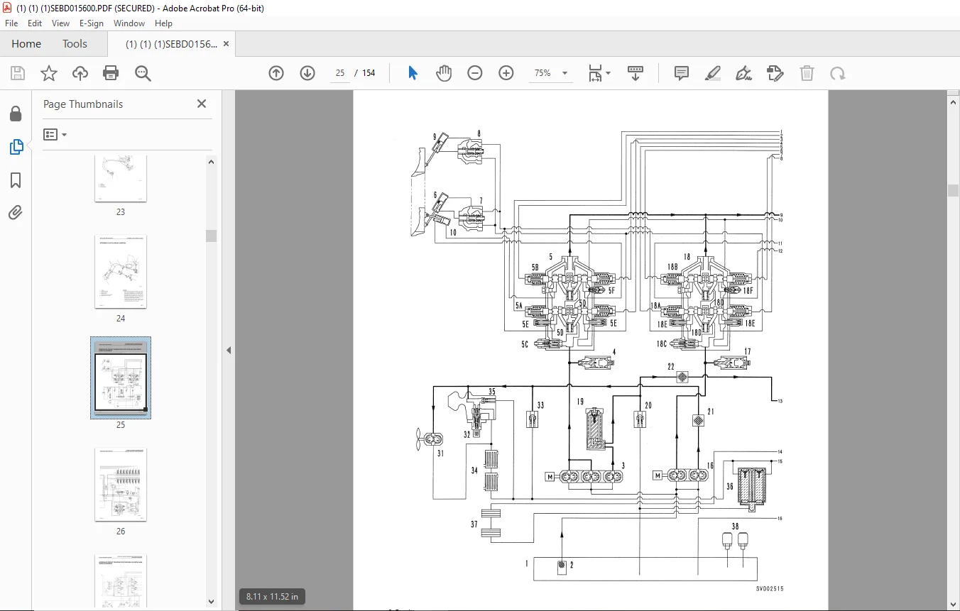
HYDRAULIC CIRCUIT SCHEMATICS FOR COOLING FAN DRIVE WORK EQUIPMENT 25
HYDRAULIC CIRCUIT DIAGRAM FOR COOLING FAN DRIVE AND WORK EQUIPMENT 27
OPERATION OF WORK EQUIPMENT CONTROL CIRCUIT 31
WORK EQUIPMENT EPC VALVE 50
RIPPER * SSC CONTROLLER (LE TYPE) 53
BLADE CONTROLLER (LX TYPE) 57
ELECTRIC LEVER 59
CLINOMETER 61
RELAY 62
SENSOR 63
WORK EQUIPMENT 65
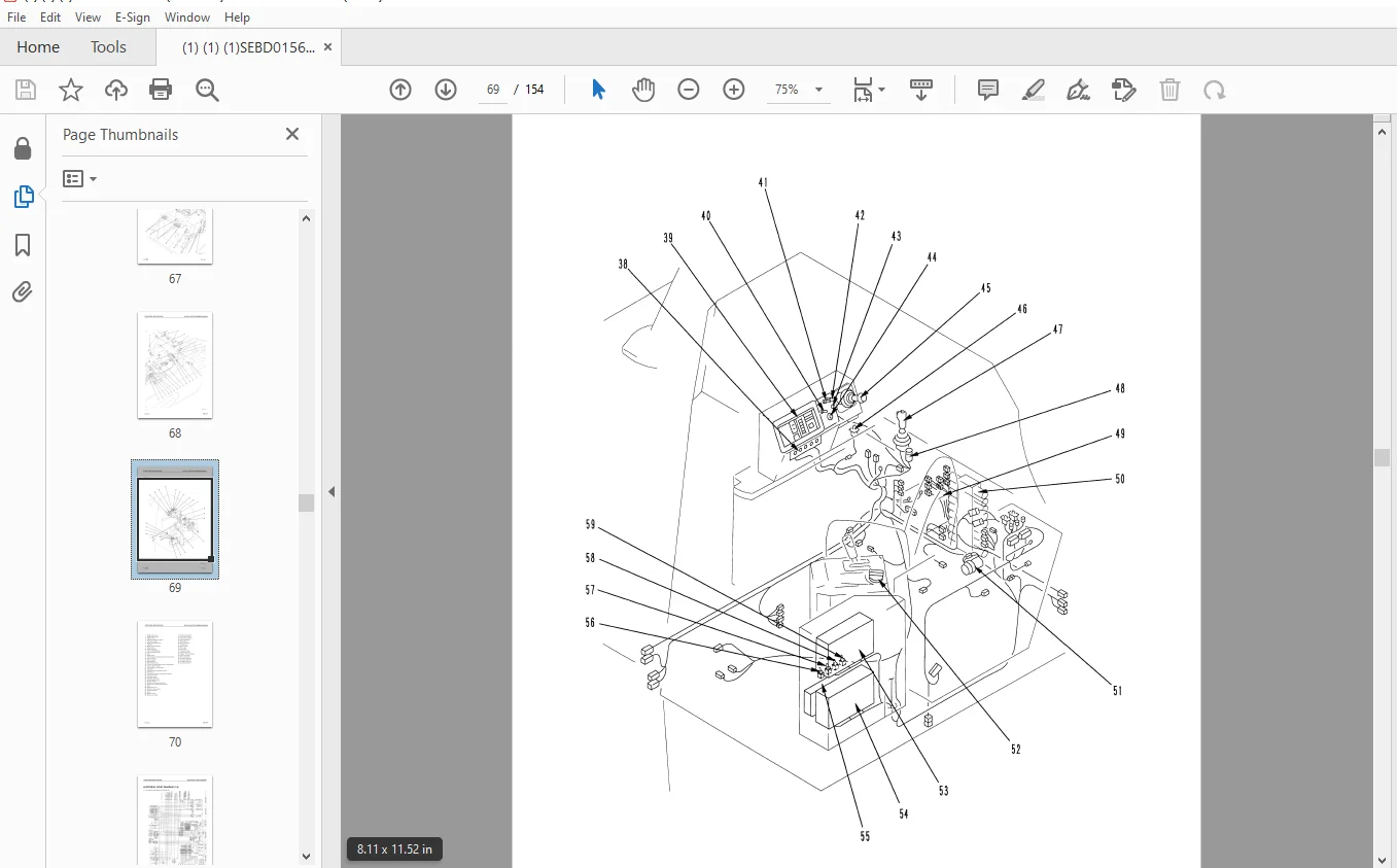
ACTUAL ELECTRIC WIRING DIAGRAM (1/2) 67
ACTUAL ELECTRIC WIRING DIAGRAM (1/2)ACTUAL ELECTRIC WIRING DIAGRAM (2/2) 69
ELECTRICAL CIRCUIT DIAGRAM (1/3) 71
ELECTRICAL CIRCUIT DIAGRAM (2/3) 72
ELECTRICAL CIRCUIT DIAGRAM (3/3) 73
ENGINE STARTING SYSTEM 74
MODE SELECTION SYSTEM 75
ENGINE CONTROL SYSTEM 80
ELPC CONTROLLER 81
ELPC ACTUATOR 83
FUEL CONTROL DIAL 93
20 TESTING AND ADJUSTING 94
TESTING AND ADJUSTING ELPC VALVE POTENTTIOMETER 95
ADJUSTING FUEL CONTROL 97
PROCEDURE FOR CLEARING MEMORY 99
TROUBLESHOOTING 100
POINTS TO REMEMBER WHEN TROUBLESHOOTING 101
SEQUENCE OF EVENTS IN TROUBLESHOOTING 102
POINTS TO REMEMBER WHEN CARRYING OUT MAINTENANCE 103
CHECKS BEFORE TROUBLESHOOTING 111
CONNECTOR TYPES AND MOUNTING LOCATIONS 112
CONNECTOR ARRANGEMENT DIAGRAM (1/3) 117
CONNECTOR ARRANGEMENT DIAGRAM (2/3) 119
CONNECTOR ARRANGEMENT DIAGRAM (3/3) 120
MONITOR PANEL, CONTROLLER DISPLAY METHOD 121
EMERGENCY SWITCH 124
ENGINE SYSTEM TROUBLESHOOTING 127
MONTOR AND MISCELLANEOUS TROUBLESHOOTING 131
POWER SOURCE TROUBLESHOOTING 134
BLADE SYSTEM TROUBLESHOOTING 137
RIPPER SYSTEM TROUBLESHOOTING 139
ERROR CODE TABLE 141
40 MAINTENANCE STANDARD 144
EPC SOLENOID VALVE 145
WORK EQUIPMENT CYLINDER 146
VARIABLE MULTIPLE LONG SHANK RIPPER 147
90 OTHERS 150
ELECTRIC CIRCUIT DIAGRAM (1/3) 151
ELECTRIC CIRCUIT DIAGRAM (2/3) 152
ELECTRIC CIRCUIT DIAGRAM (3/3) 153
DESCRIPTION:
Komatsu Bulldozer D575A-2 Shop Manual SEBM015600K – PDF DOWNLOAD
BULLDOZER
With shoe slip controller and
variable multiple long shank ripper
SERIAL NUMBERS D575A-2 10035 and up
FOREWORD
GENERAL
This shop manual has been prepared as an aid to improve the quality of repairs by giving the serviceman an accurate understanding of the product and by showing him the correct way to perform repairs and make judgements. Make sure you understand the contents of this manual and use it to full effect at every opportunity.
This shop manual mainly contains the necessary technical information for operations performed in a service workshop. For ease of understanding, the manual is divided into the following chapters; these chapters are further divided into the each main group of components.
STRUCTURE AND FUNCTION
This section explains the structure and function of each component. It serves not only to give an understanding of the structure, but also serves as reference material for troubleshooting.
TESTING AND ADJUSTING
This section explains checks to be made before and after performing repairs, as well as adjustments to be made at completion of the checks and repairs.
Troubleshooting charts correlating “Problems” to “Causes” are also included in this section.
DISASSEMBLY AND ASSEMBLY
This section explains the order to be followed when removing, installing, disassembling or assembling each component, as well as precautions to be taken for these operations.
MAINTENANCE STANDARD
This section gives the judgement standards when inspecting disassembled parts.
G.B 13/12/24