Komatsu BULLDOZER D61EX-15E0 D61PX-15E0 Shop Manual SEN02387 – PDF DOWNLOAD
$35.95
Komatsu BULLDOZER D61EX-15E0 D61PX-15E0 Shop Manual SEN02387 – PDF DOWNLOAD
Machine Model Serial number
D61EX-15E0 B45001 and up
D61PX-15E0 B45001 and up
Description
Komatsu BULLDOZER D61EX-15E0 D61PX-15E0 Shop Manual SEN02387 – PDF DOWNLOAD
FILE DETAILS:
Komatsu BULLDOZER D61EX-15E0 D61PX-15E0 Shop Manual SEN02387 – PDF DOWNLOAD
Language : English
Pages :1252
Downloadable : Yes
File Type : PDF
DESCRIPTION:
Komatsu BULLDOZER D61EX-15E0 D61PX-15E0 Shop Manual SEN02387 – PDF DOWNLOAD
Machine Model Serial number
D61EX-15E0 B45001 and up
D61PX-15E0 B45001 and up
Safety notice
Important safety notice
- Proper service and repair are extremely important for safe machine operation. The service and repair techniques recommended by Komatsu and described in this manual are both effective and safe. Some of these techniques require the use of tools specially designed by Komatsu for the specific purpose.
- To prevent injury to workers, the symbol k is used to mark safety precautions in this manual. The cautions accompanying these symbols should always be followed carefully. If any dangerous situation arises or may possibly arise, first consider safety, and take the necessary actions to deal with the situation.
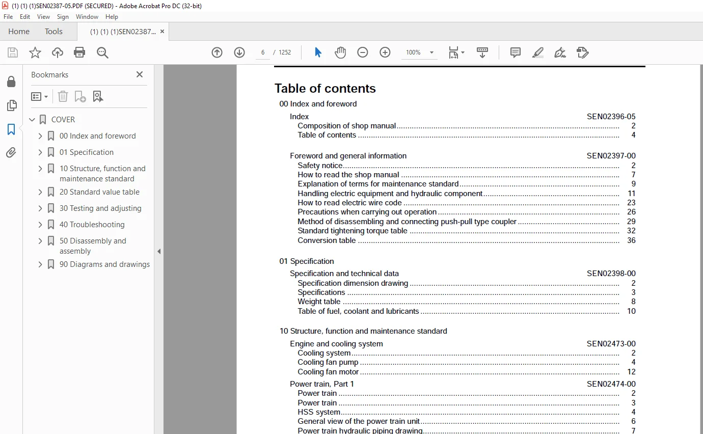
TABLE OF CONTENTS:
Komatsu BULLDOZER D61EX-15E0 D61PX-15E0 Shop Manual SEN02387 – PDF DOWNLOAD
COVER 1
00 Index and foreword 3
Index 3
Composition of shop manual 4
Table of contents 6
Foreword and general information 17
Safety notice 18
How to read the shop manual 23
Explanation of terms for maintenance standard 25
Handling electric equipment and hydraulic component 27
How to read electric wire code 39
Precautions when carrying out operation 42
Method of disassembling and connecting push-pull type coupler 45
Standard tightening torque table 48
Conversion table 52
01 Specification 59
Specification and technical data 59
Specification dimension drawing 60
Specifications 61
Weight table 66
Table of fuel, coolant and lubricants 68
10 Structure, function and maintenance standard 71
Engine and cooling system 71
Cooling system 72
Cooling fan pump 74
Cooling fan motor 82
Power train, Part 1 89
Power train 90
Power train 91
HSS system 92
General view of the power train unit 94
Power train hydraulic piping drawing 95
Transmission, steering, brake control 96
Damper and universal joint 98
Torque converter, PTO 100
Transmission 106
Transmission ECMV 118
Main relief valve and torque converter relief valve 124
Lubricating oil relief valve 126
Power train, Part 2 129
Bevel gear shaft, HSS and brake 130
Brake valve 146
Final drive 152
Undercarriage and frame 159
Main frame 161
Suspension 162
Track frame and idler cushion 166
Idler 170
Track roller 172
Carrier roller 176
Sprocket 178
Track shoe 182
Single shoe 186
Swamp shoe 186
Hydraulic system, Part 1 189
Layout of hydraulic devices for work equipment 190
Work equipment control 192
Hydraulic tank and filter 194
Scavenging pump 196
Power train and steering lubrication pump 197
HSS pump 198
HSS motor 216
Hydraulic system, Part 2 225
Control valve 226
CLSS 234
Self pressure reducing valve 261
Hydraulic system, Part 3 269
PPC valve 270
Electric lever (Steering) 286
Quick drop valve 290
Solenoid valve 292
Accumulator 294
Work equipment 297
Work equipment 298
Cutting edge and end bit 304
Ripper 305
Hydraulic cylinder 306
Piston valve 309
Cab and its attachments 311
Cab mount 312
Cab 313
Air conditioner piping diagram 315
Electrical system 317
Monitor system 318
Monitor panel 320
Engine control 328
Engine control system 329
Cooling system control system 331
System components 333
Palm command control system 341
PPC lock system 343
KOMTRAX terminal system 344
Sensor 346
20 Standard value table 351
Standard service value table 351
Standard value table for engine 352
Standard value table for machine 353
30 Testing and adjusting 363
Testing and adjusting, Part 1 363
Standard value table for engine related parts 365
Measuring engine speed 368
Measuring intake air pressure (boost pressure) 370
Measuring exhaust color 372
Adjusting valve clearance 373
Measuring compression pressure 375
Measuring blow-by pressure 378
Measuring engine oil pressure 379
Handling fuel system equipment 380
Releasing residual pressure in fuel system 380
Measuring fuel pressure 381
Measuring fuel delivery amount, return rate and leakage 383
Bleeding air from fuel circuit 387
Testing leakage in fuel system 389
Handling of reduced cylinder mode operation 390
Handling of no injection cranking operation 390
Testing and adjusting air conditioner compressor belt tension 391
Replacing the fan belt 391
Handling controller voltage circuit 392
Adjusting fuel control dial and decelerator pedal 393
Testing and adjusting, Part 2 397
Measuring power train oil pressure 399
Adjusting transmission speed sensor (replacement procedure) 403
Simple method of testing brake performance 405
Adjusting brake pedal 406
Adjusting parking brake lever 408
Emergency escape method when power train has trouble 409
Adjusting idler clearance 412
Inspecting wear of sprocket 412
Testing and adjusting track shoe tension 413
Testing and adjusting work equipment and HSS oil pressure 414
Testing control circuit main pressure 418
Measuring PPC valve output pressure 419
Adjusting play of work equipment PPC valve 422
Measuring internal leakage of work equipment cylinder 423
Adjusting work equipment lock lever of work equipment 424
Releasing residual pressure in work equipment cylinder (If PPC accumulator is not installed) 425
Releasing residual pressure in work equipment cylinder (If PPC accumulator is installed) 425
Bleeding air from work equipment cylinder 426
Measuring fan motor speed 427
Measuring fan pump circuit pressure 428
Measuring HSS motor oil leakage 429
Bleeding air from fan pump 429
Testing and adjusting operator’s cab 430
Testing and adjusting, Part 3 437
Testing and adjusting, Part 2 438
Special functions of monitor panel (EMMS) 438
Testing and adjusting, Part 4 477
Handling of voltage circuit of engine controller 478
Adjustment method when controller has been replaced 478
Preparatory work for troubleshooting for electric system 480
Inspection procedure of diode 485
Pm-Clinic service 486
How to start operation of KOMTRAX terminal 504
Lamp display of KOMTRAX terminal 508
40 Troubleshooting 513
Failure code table and fuse locations 513
Failure code table 514
Fuse locations 521
General information on troubleshooting 525
Points to remember when troubleshooting 526
Sequence of events in troubleshooting 527
Checks before troubleshooting 528
Classification and procedures of troubleshooting 529
Contents of troubleshooting table 530
Wiring table for connector pin numbers 534
T-adapter box and T-adapter table 567
Troubleshooting by failure code (Display of code), Part 1 571
Failure code [1500L0] Transmission clutch: Dual engagement 573
Failure code [15SAL1] Forward clutch: Fill signal is ON when command current is OFF 574
Failure code [15SALH] Forward clutch: Fill signal is OFF when command current is ON 576
Failure code [15SBL1] Reverse clutch: Fill signal is ON when command current is OFF 578
Failure code [15SBLH] Reverse clutch: Fill signal is OFF when command current is ON 580
Failure code [15SEL1] 1st clutch: Fill signal is ON when command current is OFF 582
Failure code [15SELH] 1st clutch: Fill signal is OFF when command current is ON 584
Failure code [15SFL1] 2nd clutch: Fill signal is ON when command current is OFF 586
Failure code [15SFLH] 2nd clutch: Fill signal is OFF when command current is ON 588
Failure code [15SGL1] 3rd clutch: Fill signal is ON when command current is OFF 590
Failure code [15SGLH] 3rd clutch: Fill signal is OFF when command current is ON 592
Failure code [AB00MA] Alternator: Malfunction 594
Failure code [B@BAZG] Engine oil: Oil pressure too low 594
Failure code [B@BCNS] Radiator coolant: Overheat 595
Failure code [B@CENS] Power train oil: Overheat 595
Failure code [B@HANS] Hydraulic oil: Overheat 596
Failure code [CA111] Engine controller: Abnormality in controller 597
Failure code [CA115] Abnormal engine Ne and Bkup speed sensors: Abnormal speed sensor signal 597
Failure code [CA122] Charge pressure sensor too high: Excessively high voltage detected 598
Failure code [CA123] Charge pressure sensor too low: Excessively low voltage detected 600
Failure code [CA131] Decelerator pedal sensor too high: Excessively high voltage detected 602
Failure code [CA132] Decelerator pedal sensor too low: Excessively low voltage detected 604
Failure code [CA144] Coolant temperature sensor too high: Excessively high voltage detected 606
Failure code [CA145] Coolant temperature sensor too low: Excessively low voltage detected 608
Failure code [CA153] Charge temperature sensor too high: Excessively high voltage detected 610
Failure code [CA154] Charge temperature sensor too low: Excessively low voltage detected 612
Failure code [CA155] Charge temperature too high and engine speed derated: Exceeded upper control limit of temperature 614
Failure code [CA187] Sensor power source 2 too low: Excessively low voltage detected 616
Failure code [CA221] Atmospheric pressure sensor too high: Excessively high voltage detected 618
Failure code [CA222] Atmospheric pressure sensor too low: Excessively low voltage detected 620
Failure code [CA227] Sensor power source 2 too high: Excessively high voltage detected 622
Failure code [CA234] Engine over speed: Excessively high speed 624
Failure code [CA238] Abnormal power source for Ne speed sensor: Excessively low voltage detected 625
Failure code [CA271] IMV/PCV1 short circuit: Short circuit 626
Failure code [CA272] IMV/PCV1 disconnection: Disconnection 628
Troubleshooting by failure code (Display of code), Part 2 631
Failure code [CA322] Injector No 1 system disconnection or short circuit: disconnection, short circuit 634
Failure code [CA323] Injector No 5 system disconnection or short circuit: disconnection, short circuit 636
Failure code [CA324] Injector No 3 system disconnection or short circuit: disconnection, short circuit 638
Failure code [CA325] Injector No 6 system disconnection or short circuit: disconnection, short circuit 640
Failure code [CA331] Injector No 2 system disconnection or short circuit: disconnection, short circuit 642
Failure code [CA332] Injector No 4 system disconnection or short circuit: disconnection, short circuit 644
Failure code [CA342] Engine controller data matching error: matching error 646
Failure code [CA352] Sensor power source 1 too low: Excessively low voltage detected 648
Failure code [CA386] Sensor power source 1 too high: Excessively high voltage detected 650
Failure code [CA428] Water detection sensor too high: Excessively high voltage detected 652
Failure code [CA429] Water detection sensor too low: Excessively low voltage detected 654
Failure code [CA435] Abnormal engine oil pressure switch: Abnormal signal circuit 656
Failure code [CA441] Power source voltage too low: Excessively low voltage detected 658
Failure code [CA442] Power source voltage too high: Excessively high voltage has occurred in the controller power source circuit 660
Failure code [CA449] Common rail pressure too high (2): Excessively high pressure trouble occurred 662
Failure code [CA451] Common rail pressure sensor too high: Excessively high voltage detected 664
Failure code [CA452] Common rail pressure sensor too low: Excessively low voltage detected 666
Failure code [CA488] Charge temperature too high and torque derated: Exceeded upper control limit of temperature 668
Failure code [CA553] Common rail pressure too high (1): Excessively high pressure detected 669
Failure code [CA559] Loss of pressure feed from supply pump (1): Loss of pressure feed detected 670
Failure code [CA689] Abnormal engine Ne speed sensor: Abnormal signal 672
Failure code [CA731] Abnormal engine Bkup speed sensor phase: Abnormal phase 674
Failure code [CA757] Loss of all engine controller data: Loss of all data 676
Failure code [CA778] Abnormal engine Bkup speed sensor: Abnormal Bkup signal 678
Failure code [CA1633] Abnormal KOMNET: Abnormal communication 680
Failure code [CA2185] Decelerator pedal sensor power source too high: Excessively high voltage detected 682
Failure code [CA2186] Decelerator pedal sensor power source too low: Excessively low voltage detected 684
Failure code [CA2249] Loss of pressure feed from supply pump (2): Loss of pressure feed detected 686
Failure code [CA2311] Abnormal IMV solenoid: Abnormal resistance 688
Failure code [CA2555] Air intake heater relay disconnection: Disconnection 690
Failure code [CA2556] Air intake heater relay short circuit: Short circuit 692
Troubleshooting by failure code (Display of code), Part 3 695
Failure code [D110KA] Battery relay: Short circuit 698
Failure code [D110KB] Battery relay: Disconnection 700
Failure code [D130KA] Neutral safety relay: Short circuit 702
Failure code [D130KB] Neutral safety relay: Disconnection 704
Failure code [D161KA] Back-up alarm relay: Disconnection 706
Failure code [D161KB] Back-up alarm relay: Short circuit 708
Failure code [DAFRKR] Monitor panel CAN communication: Defective communication 710
Failure code [DAQ0KT] [DB30KT] Steering and transmission controller: Abnormality in controller 712
Failure code [DAQ1KK] [DB31KK] Main power source of steering and transmission controller: Power source voltage drop and input 714
Failure code [DAQ2KK] [DB32KK] Load power source of steering and transmission controller: Power source voltage drop and input 716
Failure code [DAQ5KK] [DB35KK] Steering and transmission controller sensor 5 V power source: Power source voltage drop and input 718
Failure code [DAQ6KK] [DB36KK] Steering and transmission controller sensor 24 V power source: Power source voltage drop and input 720
Failure code [DAQ9KQ] [DB39KQ] Steering and transmission controller model selection: Inconsistency in model select signal 722
Failure code [DB2RKR] Steering and transmission controller CAN communication: Defective communication 724
Failure code [DB30KT] [DAQ0KT] Steering and transmission controller: Abnormality in controller 726
Failure code [DB31KK] [DAQ1KK] Main power source of steering and transmission controller: Power source voltage drop and input 726
Failure code [DAB32KK] [DAQ2KK] Load power source of steering and transmission controller: Power source voltage drop and input 726
Failure code [DB35KK] [DAQ5KK] Steering and transmission controller sensor 5 V power source: Power source voltage drop and input 726
Failure code [DB36KK] [DAQ6KK] Steering and transmission controller sensor 24 V power source: Power source voltage drop and input 726
Failure code [DB39KQ] [DAQ9KQ] Steering and transmission controller model selection: Inconsistency in model select signal 726
Failure code [DD12KA] Shift up switch: Disconnection 728
Failure code [DD12KB] Shift up switch: Short circuit 730
Failure code [DD13KA] Shift down switch: Disconnection 732
Failure code [DD13KB] Shift down switch: Short circuit 734
Failure code [DD14KA] [DDQ2KA] Parking brake lever switch: Disconnection 736
Failure code [DD14KB] [DDQ2KB] Parking brake lever switch: Short circuit 738
Failure code [DDQ2KA] [DD14KA] Parking brake lever switch: Disconnection 740
Failure code [DDQ2KB] [DD14KB] Parking brake lever switch: Short circuit 740
Failure code [DGS1KX] Hydraulic oil temperature sensor: Input signal is out of normal range 742
Failure code [DGT1KA] Power train oil temperature sensor: Disconnection 744
Failure code [DGT1KX] Power train oil temperature sensor: Input signal is out of normal range 745
Failure code [DK10KA] Fuel dial: Disconnection 746
Failure code [DK10KB] Fuel dial: Short circuit 748
Failure code [DK30KA] Steering potentiometer (1): Disconnection 750
Failure code [DK30KB] Steering potentiometer (1): Short circuit 752
Failure code [DK30KX] Steering potentiometer: Input signal is out of normal range 754
Failure code [DK30KZ] Steering potentiometer: Disconnection or short circuit (Double failure) 755
Failure code [DK30L8] Steering potentiometer: Inconsistent analog signal 755
Failure code [DK31KA] Steering potentiometer (2): Disconnection 756
Failure code [DK31KB] Steering potentiometer (2): Short circuit 758
Failure code [DK40KA] Brake potentiometer: Disconnection 760
Failure code [DK40KB] Brake potentiometer: Short circuit 761
Troubleshooting by failure code (Display of code), Part 4 763
Failure code [DK55KX] Forward-reverse potentiometer: Input signal is out of normal range 765
Failure code [DK55KZ] Forward-reverse potentiometer: Disconnection or short circuit (Double failure) 766
Failure code [DK55L8] Forward-reverse potentiometer: Inconsistent analog signal 767
Failure code [DK56KA] Forward-reverse potentiometer (1): Short circuit 768
Failure code [DK56KB] Forward-reverse potentiometer (1): Disconnection 770
Failure code [DK57KA] Forward-reverse potentiometer (2): Disconnection 772
Failure code [DK57KB] Forward-reverse potentiometer (2): Short circuit 774
Failure code [DKH1KA] [DKH1KX] Pitch angle sensor: Short circuit 776
Failure code [DKH1KB] [DKH1KX] Pitch angle sensor: Disconnection 778
Failure code [DKH1KX], [DKH1KA] or [DKH1KB] Pitch angle sensor: Input signal out of range 779
Failure code [DLT3KA] Transmission output speed sensor: Disconnection 780
Failure code [DLT3KB] Transmission output speed sensor: Short circuit 781
Failure code [DV00KB] Alarm buzzer: Short circuit 782
Failure code [DW7BKA] Fan reverse solenoid: Disconnection 783
Failure code [DW7BKB] Fan reverse solenoid: Short circuit 784
Failure code [DWN1KA] HSS EPC solenoid right: Disconnection 785
Failure code [DWN1KB] HSS EPC solenoid right: Short circuit 786
Failure code [DWN1KY] HSS EPC solenoid right: Short circuit to power source line 787
Failure code [DWN2KA] HSS EPC solenoid left: Disconnection 788
Failure code [DWN2KB] HSS EPC solenoid left: Short circuit 789
Failure code [DWN2KY] HSS EPC solenoid left: Short circuit to power source line 790
Failure code [DWN5KA] Fan pump TVC solenoid: Disconnection 791
Failure code [DWN5KB] Fan pump TVC solenoid: Short circuit 792
Failure code [DWN5KY] Fan pump TVC solenoid: Short circuit in power source line 793
Failure code [DXA0KA] HSS pump TVC solenoid: Disconnection 794
Failure code [DXA0KB] HSS pump TVC solenoid: Short circuit 795
Failure code [DXA0KY] HSS pump TVC solenoid: Short circuit to power source line 796
Failure code [DXH4KA] 1st clutch ECMV: Disconnection 797
Failure code [DXH4KB] 1st clutch ECMV: Short circuit 798
Failure code [DXH4KY] 1st clutch ECMV: Short circuit to power source line 800
Failure code [DXH5KA] 2nd clutch ECMV: Disconnection 801
Failure code [DXH5KB] 2nd clutch ECMV: Short circuit 802
Failure code [DXH5KY] 2nd clutch ECMV: Short circuit to power source line 804
Failure code [DXH6KA] 3rd clutch ECMV: Disconnection 805
Failure code [DXH6KB] 3rd clutch ECMV: Short circuit 806
Failure code [DXH6KY] 3rd clutch ECMV: Short circuit to power source line 808
Failure code [DXH7KA] Reverse clutch ECMV: Disconnection 809
Failure code [DXH7KB] Reverse clutch ECMV: Short circuit 810
Failure code [DXH7KY] Reverse clutch ECMV: Short circuit to power source line 811
Failure code [DXH8KA] Forward clutch ECMV: Disconnection 812
Failure code [DXH8KB] Forward clutch ECMV: Short circuit 814
Failure code [DXH8KY] Forward clutch ECMV: Short circuit to power source line 816
Troubleshooting of electrical system (E-mode) 819
Before troubleshooting of electrical system 821
Contents of troubleshooting table 823
E-1 The engine does not start (the starting motor does not turn) 825
E-2 The preheater does not operate 829
E-3 The monitor panel does not light up at all when the starting switch is turned ON 832
E-4 When the starting switch is turned on, the monitor panel completely remains lighted and does not go out 833
E-5 While the engine is running, the battery charge level caution lamp flashes 834
E-6 While the engine is running, the emergency warning item flashes 836
E-7 While the preheater is operating, the preheating pilot lamp does not light up 840
E-8 The coolant temperature gauge does not indicate correctly 842
E-9 The power train oil temperature gauge does not indicate correctly 844
E-10 Hydraulic oil temperature gauge does not indicate properly 846
E-11 Fuel gauge does not indicate properly 848
E-12 Gear speed and engine speed are not indicated properly 849
E-13 The preset mode service meter does not indicate normally 849
E-14 The warning lamp does not flash or does not go out 849
E-15 The alarm buzzer does not sound or does not stop 850
E-16 Auto shift down is not possible or is not released 852
E-17 The buzzer cancel switch does not work 854
E-18 The information switch does not work 856
E-19 The fan cleaning does not operate or cannot be reset 858
E-20 The preset mode does not operate or cannot be reset 860
E-21 The monitor panel cannot be set in the service mode or cannot be set out of the service mode 862
E-22 The back-up alarm does not sound 864
E-23 The head lamp and rear lamp do not light up 867
E-24 The horn does not sound or does not stop 870
E-25 Malfunction of wipers 872
E-26 Washer does not spray water 888
E-27 The air conditioner does not operate 894
E-28 KOMTRAX system does not operate normally 898
Troubleshooting of hydraulic and mechanical system (H-mode) 901
Contents of troubleshooting table 903
H-1 There is no travel power (no drawbar pull) 904
H-2 Machine does not move (at 2nd or 3rd speed) 905
H-3 Machine does not move at any gear speed 906
H-4 Machine travels only in one direction, forward or in reverse 907
H-5 When gear is shifted or travel direction is changed, large time lag is made 908
H-6 Machine cannot be steered (Machine does not turn leftward or rightward) 909
H-7 Steering speed or power is low 909
H-8 Brake does not work 910
H-9 Overheat of power train oil 911
H-10 Abnormal sound comes out from around HSS and work equipment pump or HSS motor 912
H-11 All work equipment speeds are slow 912
H-12 Work equipment does not move 913
H-13 Blade lift speed is slow or lacks power 913
H-14 Blade tilt speed is slow or lacks power 914
H-15 Angling blade speed is slow or lacks power 914
H-16 Ripper lift speed is slow or lacks power 915
H-17 Excessive hydraulic drift of blade lift 915
H-18 Excessive hydraulic drift of blade tilt 916
H-19 Excessive hydraulic drift of blade angle 916
H-20 Excessive hydraulic drift of ripper lift 917
Troubleshooting of engine (S-mode) 919
Method of using troubleshooting charts 921
S-1 Starting performance is poor 924
S-2 Engine does not start 925
S-3 Engine does not pick up smoothly 928
S-4 Engine stops during operations 929
S-5 Engine does not rotate smoothly 930
S-6 Engine lacks output (or lacks power) 931
S-7 Exhaust smoke is black (incomplete combustion) 932
S-8 Oil consumption is excessive (or exhaust smoke is blue) 933
S-9 Oil becomes contaminated quickly 934
S-10 Fuel consumption is excessive 935
S-11 Oil is in coolant (or coolant spurts back or coolant level goes down) 936
S-12 Oil pressure drops 937
S-13 Oil level rises (Entry of coolant or fuel) 938
S-14 Coolant temperature becomes too high (overheating) 939
S-15 Abnormal noise is made 940
S-16 Vibration is excessive 941
50 Disassembly and assembly 943
General information on disassembly and assembly 943
How to read this manual 944
Coating materials list 946
Special tool list 949
Sketches of special tools 956
Engine and cooling system (SAA6D107E-1) 967
Removal and installation of radiator guard assembly 968
Removal and installation of engine assembly 972
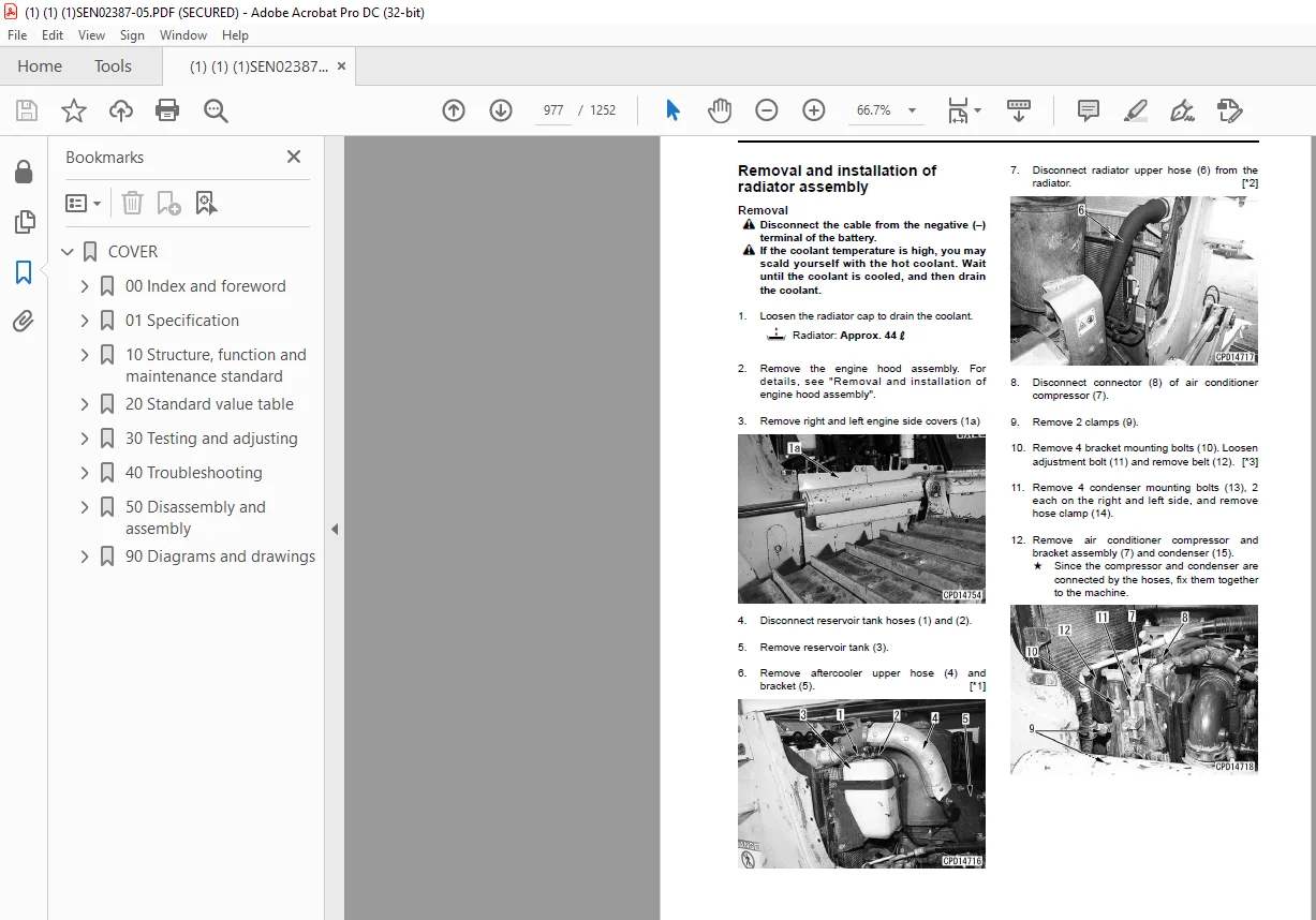
Removal and installation of radiator assembly 977
Removal and installation of aftercooler assembly 980
Removal and installation of power train oil cooler assembly 983
Removal and installation of hydraulic cooler assembly 984
Removal and installation of cooling fan drive assembly 987
Removal and installation of cooling fan motor assembly 989
Removal and installation of damper assembly 990
Removal and installation of fuel tank assembly 995
Removal and installation of engine hood assembly 997
Engine (SAA6D170E-1) 999
Removal and installation of fuel supply pump assembly1000
Removal and installation of fuel injector assembly1002
Removal and installation of cylinder head assembly1011
Removal and installation of engine front seal1024
Removal and installation of engine rear seal1027
Power train, Part 11031
Removal and installation of PTO, torque converter and transmission assembly1032
Disconnection and connection of PTO, torque converter and transmission assembly1036
Disassembly and assembly of PTO assembly1038
Disassembly and assembly of torque converter assembly1043
Disassembly and assembly of TORQFLOW transmission assembly1047
Removal and installation of torque converter main relief valve assembly1064
Disassembly and assembly of torque converter main relief valve assembly1065
Power train, Part 21067
Removal and installation of power train and lubricating oil pump assembly1068
Removal and installation of HSS and work equipment pump assembly1070
Removal and installation of scavenging pump assembly1071
Removal and installation of HSS motor assembly1071
Disassembly and assembly of HSS assembly1072
Removal and installation of final drive assembly1090
Disassembly and assembly of final drive assembly1091
Undercarriage and frame, Part 11105
Removal and installation of track frame assembly1106
Removal and installation of idler assembly1108
Disassembly and assembly of idler assembly1109
Removal and installation of recoil spring assembly1113
Disassembly and assembly of recoil spring assembly1114
Removal and installation of track roller assembly1117
Disassembly and assembly of track roller assembly1118
Removal and installation of carrier roller assembly1121
Disassembly and assembly of carrier roller assembly1122
Expansion and installation of track shoe assembly (Plus type track shoe)1130
Undercarriage and frame, Part 21127
Check before expanding track shoe assembly1128
Expansion (normal), expansion (internal abnormality) and installation of track shoe assembly (Conventional type track shoe)1128
Overall disassembly and overall assembly of track shoe assembly (Conventional type track shoe)1131
Link press-fitting jig dimensions table1147
Field disassembly and assembly of one link (Conventional type track shoe)1155
Field disassembly and assembly of one link (PLUS type track shoe)1162
Removal and installation of pivot shaft assembly1167
Removal and installation of equalizer bar assembly1169
Removal and installation of equalizer bar side bushing1170
Removal and installation of segment teeth1171
Overall disassembly and overall assembly of track shoe assembly (PLUS type track shoe)1148
Hydraulic system1173
Removal and installation of main control valve assembly1174
Assembly of main control valve assembly1176
Removal and installation of cooling fan pump assembly1179
Disassembly and assembly of hydraulic cylinder assembly1180
Work equipment1187
Removal and installation of work equipment assembly1188
Disassembly and assembly of work equipment assembly1190
Cab and its attachments1195
Removal and installation of ROPS guard1196
Removal and installation of operator’s cab assembly1197
Removal and installation of operator’s cab glass (stuck glass)1203
Removal and installation of monitor panel assembly1212
Removal and installation of dashboard assembly1213
Removal and installation of floor frame assembly1216
Electrical system1223
Removal and installation of engine controller assembly1224
Removal and installation of steering and transmission controller assembly1225
Removal and installation of KOMTRAX terminal assembly1226
Removal and installation of air conditioner unit assembly1227
90 Diagrams and drawings1233
Power train hydraulic circuit diagram1235
Work equipment hydraulic circuit diagram1236
Electrical diagrams and drawings1240
Connector arrangement diagram1250
IMAGES PREVIEW OF THE MANUAL:
![]()
![]()
![]()
S.M 13/12/24